1998 HONDA INTEGRA airbag off
[x] Cancel search: airbag offPage 1335 of 1681
)
Precautions/Procedures
General Precautions
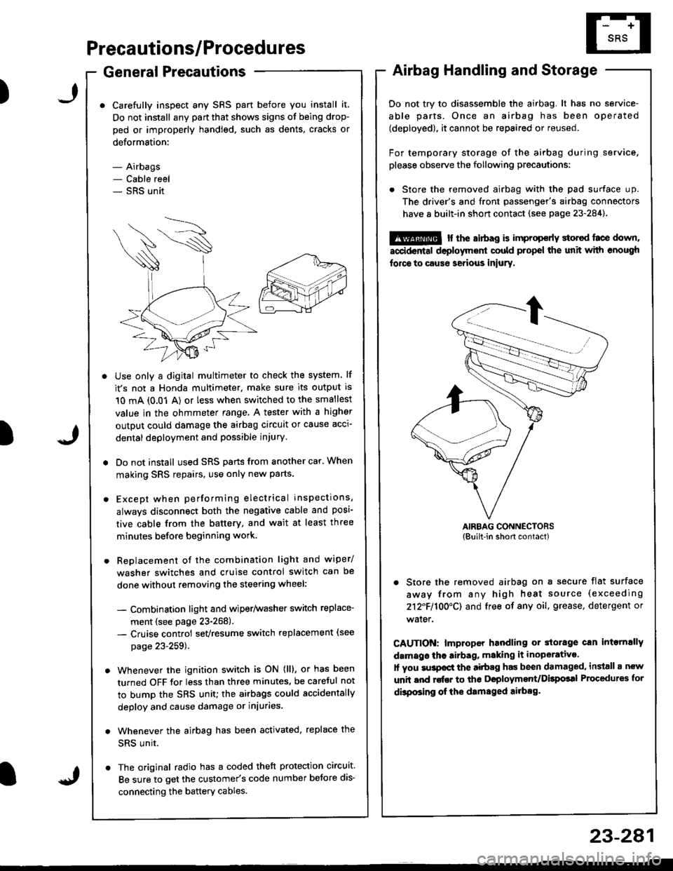
Carefully inspect any SRS part before you install it,
Do not install any part that shows signs of being drop-
ped or improperly handled. such as dents, cracks or
deformstion:
- Airbags- Cable reel- SRS unit
' Use only a digital multimeter to check the system lf
it's not a Honda multimeter. make sure its output is
10 mA (0.01 A) or less when switched to the smallest
value in the ohmmeter range. A tester with a higher
output could damage the airbag circuit or cause acci-
dental deployment and possible injury.
r Do not install used SRS parts from anothercar.When
making SRS repairs, use only new parts.
r Except when performing electrical inspections,
always disconnect both the negative cable and posl-
tive cable from the batterY, and wait at least three
minutes before beginning work.
r Replacement of the combination light and wiper/
washer switches and cruise control switch can be
done without removing the steering wheel:
- Combination light and wiperlwasher switch replace-
ment (see page 23-268).- Cruise controi sevresume switch replacement (see
page 23-259t�.
. Whenever the ignition switch is ON (ll), or has been
turned OFF for less than three minutes, be caretul not
to bump the SRS unit; the airbags could accidentally
deploy and cause damage or iniuries.
. Whenever the airbag has been activated, replace the
SRS unit.
. The original radio has a coded theft protection circuit.
Be sure to get the customer's code number beJore dis-
connecting the battery cables.
23-281
Airbag Handling and Storage
Do not try to disassemble the airbag. lt has no service-
able parts. Once an airbag has been operated
(deployed), it cannot be repaired or reused.
For temporary storage of the airbag during service,
please observe the following precautions:
. Store the removed airbag with the pad surface up.
The driver's and tront passenger's airbag connectors
have 8 built-in short contact (see page 23-284).
@ r the airbag is improp€rly storcd face down,
accidental deployment could propel the unit with enough
force to caus6 serious iniury.
AIRBAG CONNECTORS(Built-in short contact)
. Store the removed airbag on a secure flat surface
away from any high heat source (exceeding
212F110O'CI and free of any oil, grease, detergent or
water.
CAUTION: lmproper handling or storage can intornally
damags the airbag, making it inoperative.
1l you su3pocl the aitbag has been damaged, install a ncw
unit and rofEr to ths Deployment/Dilpolal Procedures for
dbposing of ihe damsged ailbag.
)
Page 1336 of 1681
Precautions/Procedu res
SRS Unit Precautions
Take extra caro when painting or doing body work in
the area below the dashboard. Avoid direct exposure
of the SRS unit or wiring to heat guns, welding, or
spraying equipment.
Disconnect the airbsg connector(s) before discon-
necting SRS harness connectors (see page 23-2851.
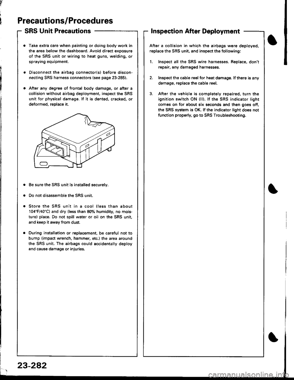
After any degree of frontal body damage, or after a
collision without airbag deployment, inspect the SRS
unit for physical damage. lf it is dented, cracked, or
deformed, reDlace it.
Be sure the SRS unit is installed securelv.
Do not disassemble the SRS unit.
Store the SRS unit in a cool (lass than about
104'F/40"C) and dry (less than 80% humidity, no mois-
ture) place, Do not spill water or oil on the SRS unit,
and keeD it awav trom dust.
During installation or r6placement, be careful not to
bump {impact wrench, hammer, etc.) the area around
the SRS unit. The airbags could accidentally deploy
and cause damsge or injuries,
v
Inspection After Deployment
After a collision in which the airbags w6re deployed,
replace the SRS unit, and inspect the following:
1, Inspect all the SRS wire harnesses. Replace, don't
repair, any damaged harnesses
2. Inspect the cable reel for heat damage. lf there is any
damage. replace the cable reel.
3. After the vehicle is completely repairod, turn the
ignition switch ON {ll). lf the SRS indicator light
comes on for about six seconds and then goes off,
the SRS system is OK. lf the indicator light does not
function properly. go to SRS Troubleshooting.
23-282
Page 1339 of 1681
Disconnecting the Airbag Connector(s)
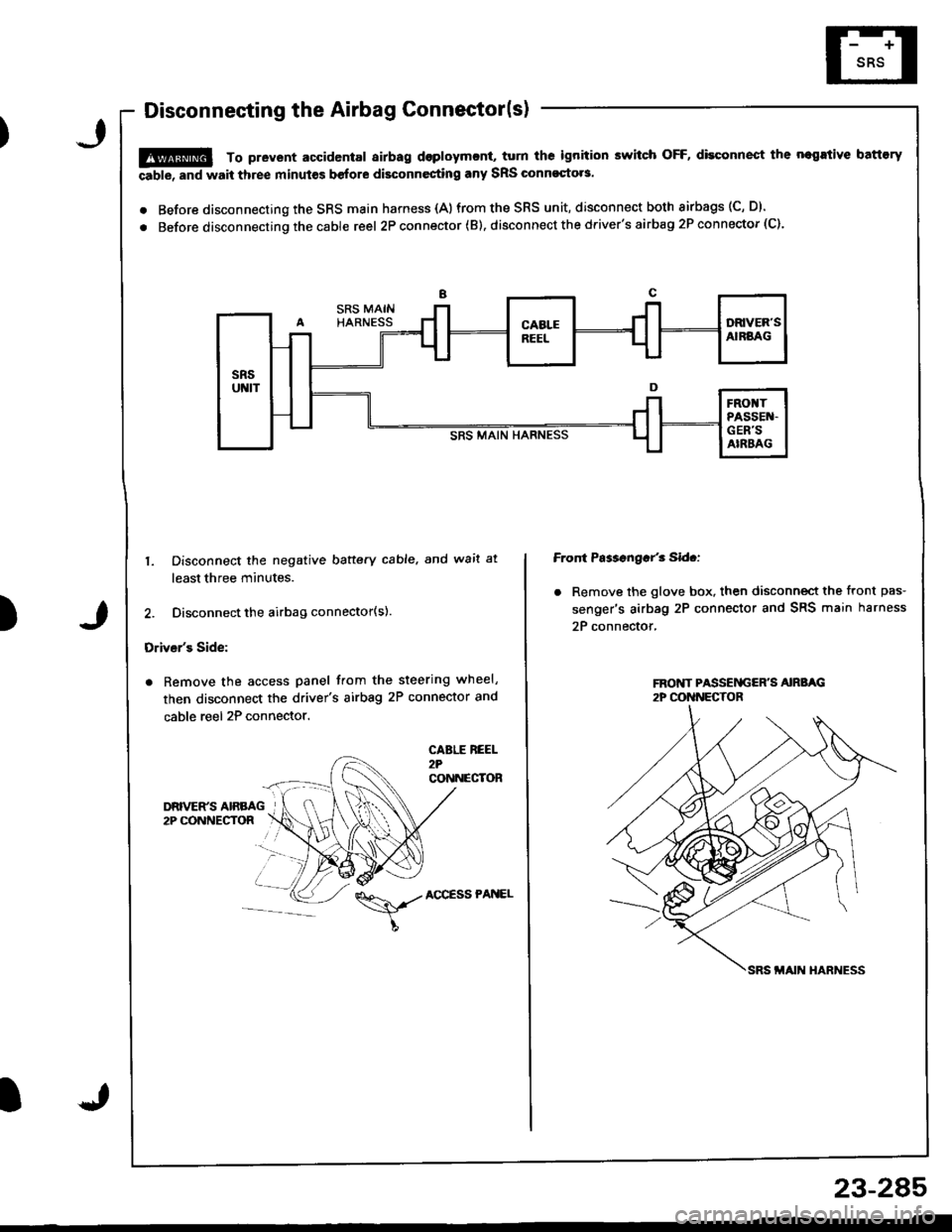
!@ To prevent accidental airbag dsploymcnt, turn ths ignition switch OFF, disconnect the negrtive battory
able, and wait three minut€s before disconnesting any SRS Glnnoqto.s.
. Before disconnecting the SRS main harness {A)from the SRS unit, disconnect both airbags (C, D).
. Before disconnecting the cable reel 2P con nector ( B). disconnect the driver's airbag 2P connector (C).
)
1. Disconnect the negative baftery cable. and wait at
least three minutes.
2. Disconnect the airbag connector(s).
Driver's Side:
. Remove the access panel from the steering wheel,
then disconnect the driver's airbag 2P connector and
cable reel 2P connector.
CABLE REEL2?CONNECTOR
Front Ps$sngar'3 Sid.:
. Remove the glove box. then disconnect the front pas-
senger's airbag 2P connector and SRS main harness
2P connector,
\,./AccEssPANEL
23-2A5
Page 1341 of 1681
)
Troubleshooting
Self-diagnostic Procedures
The self-diagnostic function of the SRS system allows it to locate the causes of system problems and to store this informa-
tion in memorv. For easier troubleshooting, this data can be retrieved via 8 dats link circuit.
o When you turn the ignition switch ON (ll), the SRS indicator will come on. lf it goes off after six seconds, the system is
normat.
. lf there is 8n abnormality, the system locstes and defines the problem, stores this information in memory, and turns
th€ SRS indicator light on. The data will remain In the memory even when the ignition switch is turned off or if the bat-
terv is disconnected.
. When you connect the SCS service connector to the service check connector (2P), and turn the ignition switch ON {ll),
the sRs indicator light will indicate the diagnostic trouble code (DTCI by th€ number of blinks.
. After reading and recording the DTC, proceed with the troubleshooting for this code
Pr6crution!
. Use only a digital multimeter to check the system, lf it's not a Honda multimeter, make sure its output is 10 mA (0.01 A)
or less when switched to the smallest value in the ohmmeter range. A tester with a higher output could damsge the
airbag circuit or cause sccidental airbag deployment and possible injury.
. Whenever the ignition switch is ON (ll), or has been turned OFF for less than three
SRS unit; the airbags could accidentally deploy and cause damage or injuries'
. Before you remove the SRS main harness, disconnect the driver's airbag connector
conneclor.
and the front passenger's airbag
. Make sure the battery is sufficiently charged (s6e psge 23-67). lf the battsry is dead or low, msasuring values won't be
correct,
a Do not touch a tester probe to the terminals in the SRS unit or harness connectors, and do not connect the terminals
with a jumper wire. Use only the backprobe set and the SCS service connector.
For backprobing spring-loaded lock type connectors, refer to psge 23-283.
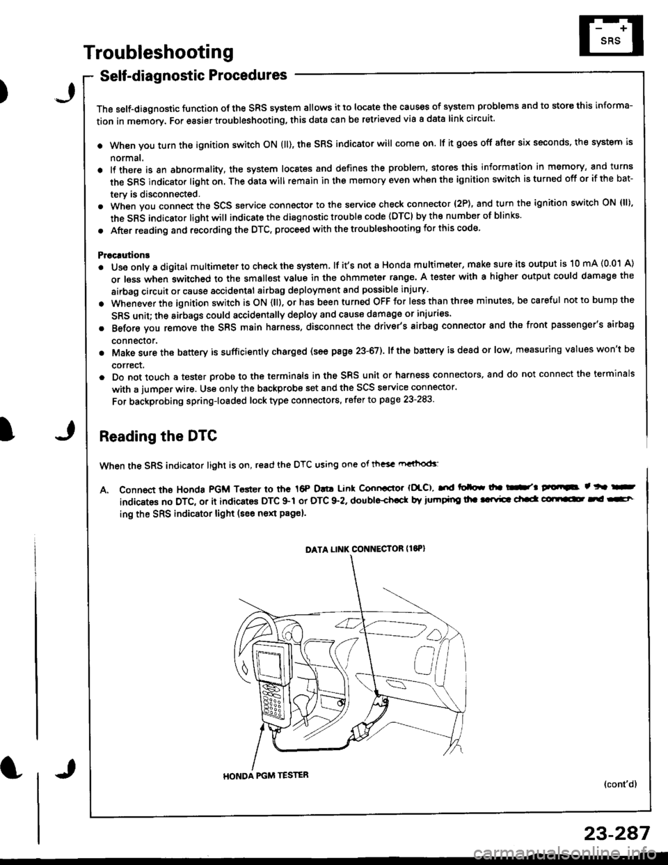
Reading the DTC
When the SRS indicator light is on, read the DTC using one ot th"sc rn"ihod<
A. Connect the Honda PGM Toster io the 16P D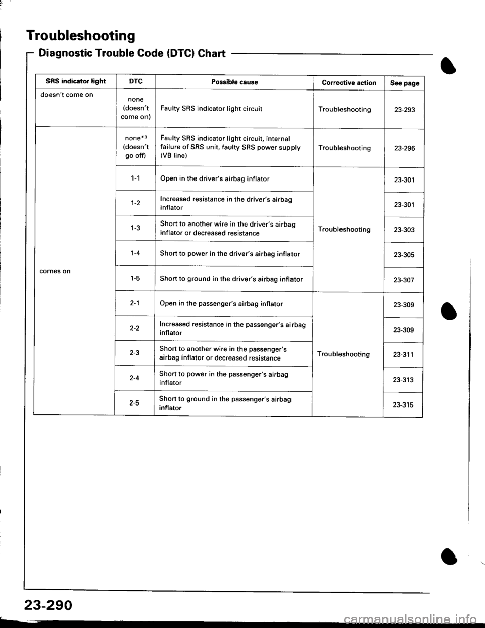
Troubleshooting
Diagnostic TroubleCode(DTC}Chart
SBS indicato. lightDTCPossible caug€Co.rective actionSee page
doesn't come onnone
{doesn't
come on)
Faulty SRS indicator light circuitTroubleshooting23-293
comes on
none*3
{doesn'tgo off)
Faulty SRS indicator light circuit, internal
failure of SRS unit, faulty SRS power supply(VB line)
Troubleshooting
'l -1Open in the driver's airbag inflator
Troubleshooting
23-301
Increased resistance in the driver's airbag
inflator23-301
1-3Short to another wire in the driver's airbao
inflato. or decreased .esistance23-303
1-4Shon to power in the driver's airbag inflator23-305
't-5Short to ground in the driver's airbag inflator23-301
2-1Open in the passenger's airbag inflator
Troubleshooting
23-309
Increased resistance in the passenger's airbag
inflator23-309
Short to another wire in the passenger's
airbag inflator or decreased resistance23-311
Short to power in the passenger's airbag
inflator23-313
z-JShort to ground in the passenger's airbag
inflator
23-290
t-
I
Page 1347 of 1681
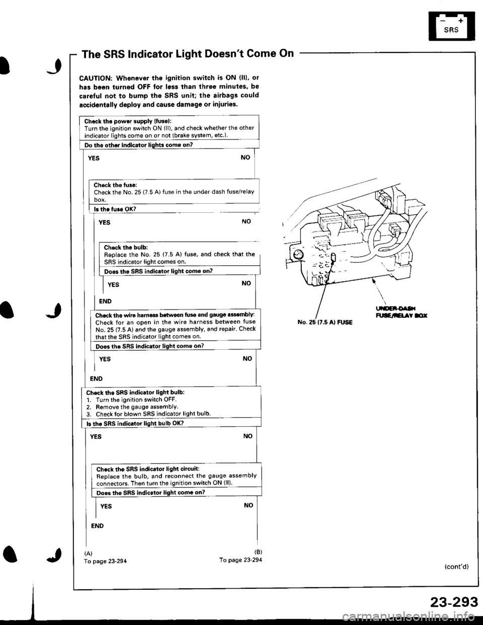
The SRS Indicator Light Doesnt Come On
CAUTION: Whenever the ignition switch is ON (lll, ol
has been turned OFF tor lsss than three minutes. be
careful not to bump the SRS unit; the airbags could
accidentslly deploy and cause damage or iniuries.
Chcck tho power supply lfuso):Turn the ignition switch ON (ll), and check whether the other
indicator lights come on or not (brake system, etc.).
Do tho oth6J indicator ligh$ come on?
NO'ES
Check ths tuse:Check the No. 25 (7.5 Ai fuse in the under dash fuse/relayho!
ls th. tu.o OK?
YESNO
Chsck the bulb:Replace the No. 25 17.5 A) fuse, and check that the
SRS indicator light comes on.
Doos tho SRS indic.lor light como on?
YES
END
Ch.ck th6 wir€ ham€ls b€twoen fu3e snd gauge .3sembly:
Check for an open in the wire harness belween tuse
No. 25 (7.5 A) and the gauge sssembly, and repair. Check
that the sRS indicator light comes on.
Doo3 the SRS indicator light come on?
YES
NO
NO
END
Ch6ck tho SRS indicator light bulb:
1. Turn the ignition switch OFF.2. Remove the gauge assemblY3. Check tor blown SRS indicator light bulb.
b tho sRs indicrlor light bulb oK?
YESNO
Check tho SRS indicator ligln circuit:ReDlace the bulb, and reconnect the gauge assembly
connectors. Then turn the ignition switch ON (ll).
Do.s tho SRS indicrtor light comG on?
I vrs NoII
END
No. 25 lt.5 Al FUSE
{A)fo page 23-294
(B)
10 page 23-294(cont'd)
Page 1349 of 1681
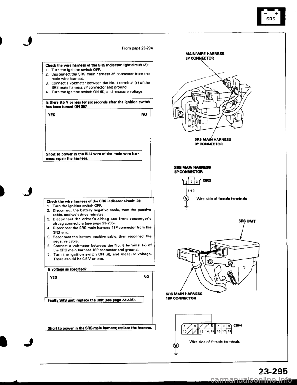
Chocktho wire h.mcas ol thc SRS Indicrtor light clrcuh l2):1. Turn the ignition switch OFF.2. Disconnect the SRS main harn€ss 3P connoctor from the
main wire harness.3. Connect a voltmeter between the No. '1 terminal {+)oltheSRS main harness 3P connector and ground,1. Turn the ignhion switch ON {ll), and measure voltag€
Ir th.rc 8.5 V or 16 toa aar t cord! tftcr rh. ignhion twitch
Shon to pow.r in th. BLU wi.o of lh. m.ln wir. h.r'
MAIN WIRE HAFNESS3P CONNECTOR
SAS MAIN HARNESSt @aa-cTof,
SRa m t{ ruE3P OOt{tCClc
)
c&
Wire sid6 of lemrla tarminaL
n00m.l I
Ch€ck lh. wir. h.rn.r. of thc SRS indic.tor circuit l3l:
1. Tlrn the ignition switch OFF.2. Oisconnoct the b8ttery negativ€ cable, then the positivo
cable, and wait throe ftinutes.
3. Disconnect the driver's airbag and front passenger's
airbag connectors (see page 23-285t'
4. Disconnect the SRS main harness 18P connector trom tho
SRS unit.5. Fsconnect the battery Dositivo cable, th€n reconnect th€
negative cable.6. Connect a voltmeter bettve€n the No. 6 terminal (+) of
th6 SRS main harness 18P connector and ground.
7. Turn the ignition switch ON (ll), and moasuro voltage.
Th€r6 should be 0.5 V or less
lr voltlsr .3 !9.cifi.d?
YESNO
F.ulty SRS unit; .cplrct th. unh {... prg. 23'326).
Shon to powe. in the SRS mrin hrtne*t taplrc.lha hmaat.
SRS UJ{'T
Wke side of temale terminals
23-295
Page 1350 of 1681
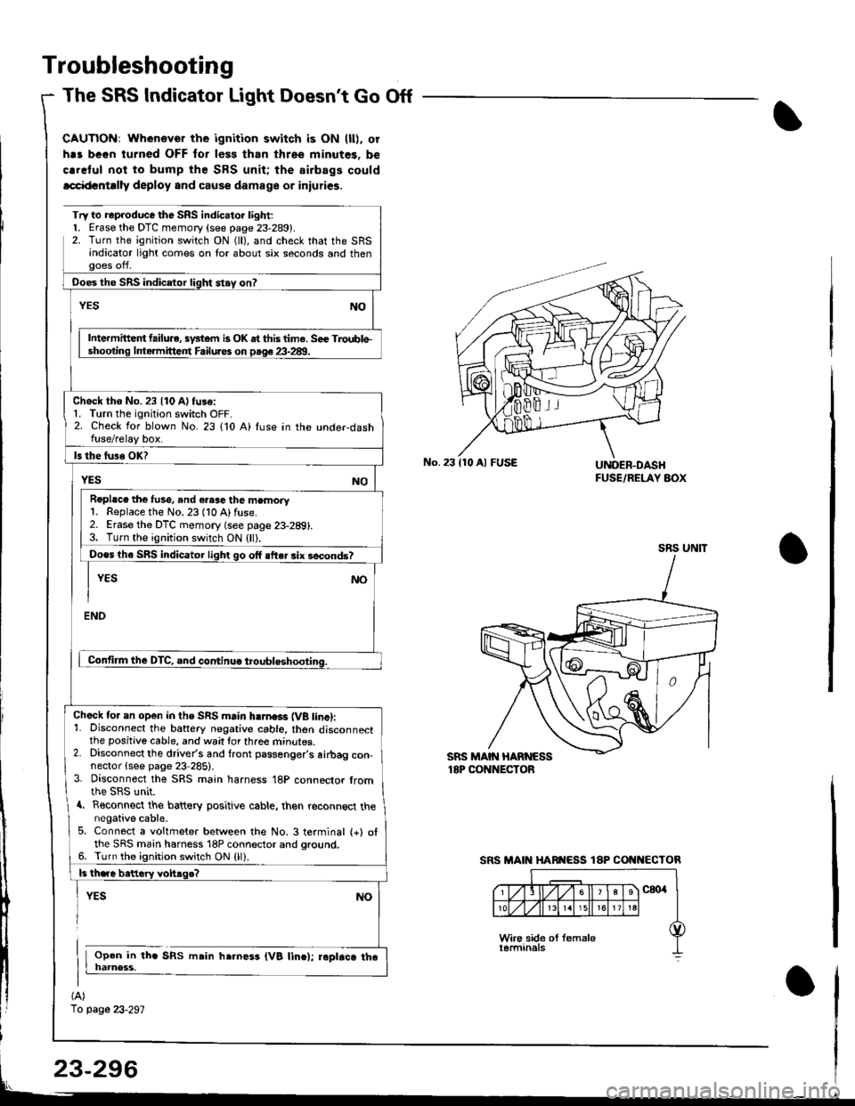
Troubleshooting
The SRS Indicator Light Doesnt Go Off
CAUTIOi{: Whenever the ignition switch is ON (ll). or
h.s bGGn turned OFF for less than three minutes. be
crrclul noi to bump the SRS unit; the airbags could
lcci{tcntrlly deploy and cause damage or iniuries.
(A)
1o page 23-297
Try to reproduce the SRS indic.tor l;ght;l. Erase the DTC memory (see page 23-289).2. Turn the ignition switch ON (ll), and check that the SRSandicator light comes on lor about six seconds and thenooes off,
Ooes the SRS indicetor light stay on?
NOYES
Intermittc t failu.e, sydem is OK dt this time. Sec Troublo-shooting lntermitteirt Failuros on p.qe 23-28!1.
Check tho No. 23 {10 A) fuse:1. Turn the ignition switch OFF-2. Check for blown No. 23 110 A) fuse in the unde.dashfuse/relay box.
ls the luse OK?
YESNO
Roplsce the f!se, and eresc the memory1. Replace the No. 23 (10 Alfuse.2. Erase the DTC memory (see page 23-289).3. Turn the ignition switch ON (ll).
Does th6 SRS indicator light go off after rix socond6?
I YEs No
I
ENO
Contilm the DTC, and continuo troubleshooting.
Check tor an open in ths SRS main hlrna3r (VB tinc):1- Disconnect the battery negative cable. thon disconnectthe positive cable, and wait tor three mrnures.2. Disconnect the driver's and front passenger's airbag con-nector (see page 23 285).3. Disconnect the SRS main harness 18P connector fromthe SRS unit.a. Reconnect the battery positive cable, then reconnect thenegative cable.5. Connect a voltmeter between the No. 3 terminal (+) otthe SRS main harness 18P connector and ground.6. Turn the ignition switch ON {ll).
ls th.re bettery vohaqe?
YES
Open in th. SRS msin h.rness (VB linc); roptrca tha
NO
No.23110 Al FUSEUNOER.DASHFUSE/RELAY AOX
SRS UNIT
SRS MAIN HARI{ESS 18P COI{I{ECTOR