1998 HONDA INTEGRA wheel
[x] Cancel search: wheelPage 1315 of 1681
Gruise Control
- Set/Resume Switch Test/Replacement {cont'dl
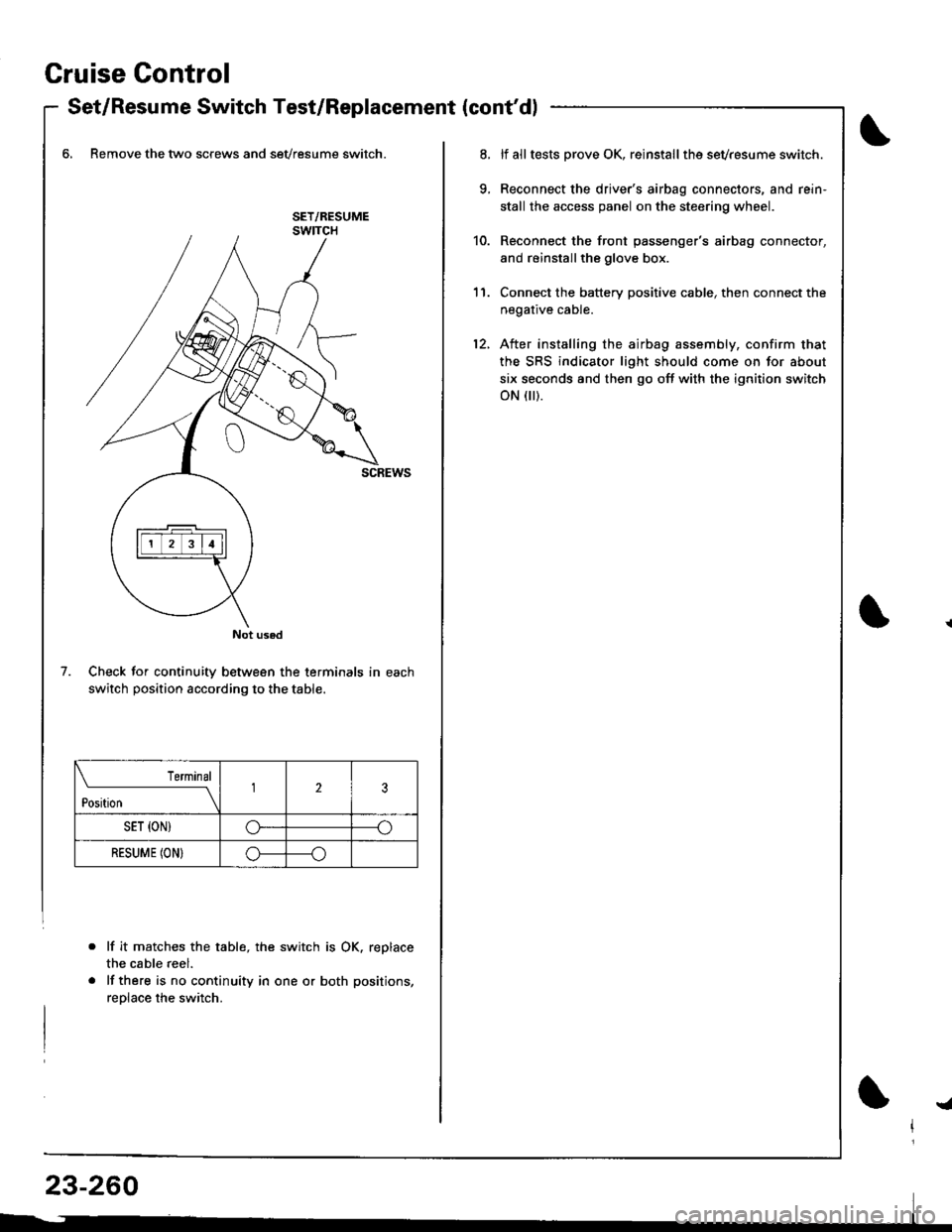
6, Remove the two screws and sevresume switch.
Check for continuity between the terminals in each
switch position according to the table.
lf it matche$ the table, the switch is OK. replace
the cable reel.
lf there is no continuity in one or both positions,
reolace the switch.
Not used
7.
Terminal
t*n*------l23
SET {ON)G----o
RESUME (ON}o----o
lf alltests prove OK, reinstallthe sevresume switch.
Reconnect the driver's airbag connectors, and rein'
stall the access panel on the steering wheel.
Reconnect the front passenger's airbag connector,
and reinstallthe glove box.
Connect the battery positive cable, then connect the
negative cable.
After installing the airbag assembly, confirm that
the SRS indicator light should come on for about
six seconds and then go off with the ignition switch
oN flr).
11.
12.
!a
Page 1335 of 1681
)
Precautions/Procedures
General Precautions
Carefully inspect any SRS part before you install it,
Do not install any part that shows signs of being drop-
ped or improperly handled. such as dents, cracks or
deformstion:
- Airbags- Cable reel- SRS unit
' Use only a digital multimeter to check the system lf
it's not a Honda multimeter. make sure its output is
10 mA (0.01 A) or less when switched to the smallest
value in the ohmmeter range. A tester with a higher
output could damage the airbag circuit or cause acci-
dental deployment and possible injury.
r Do not install used SRS parts from anothercar.When
making SRS repairs, use only new parts.
r Except when performing electrical inspections,
always disconnect both the negative cable and posl-
tive cable from the batterY, and wait at least three
minutes before beginning work.
r Replacement of the combination light and wiper/
washer switches and cruise control switch can be
done without removing the steering wheel:
- Combination light and wiperlwasher switch replace-
ment (see page 23-268).- Cruise controi sevresume switch replacement (see
page 23-259t�.
. Whenever the ignition switch is ON (ll), or has been
turned OFF for less than three minutes, be caretul not
to bump the SRS unit; the airbags could accidentally
deploy and cause damage or iniuries.
. Whenever the airbag has been activated, replace the
SRS unit.
. The original radio has a coded theft protection circuit.
Be sure to get the customer's code number beJore dis-
connecting the battery cables.
23-281
Airbag Handling and Storage
Do not try to disassemble the airbag. lt has no service-
able parts. Once an airbag has been operated
(deployed), it cannot be repaired or reused.
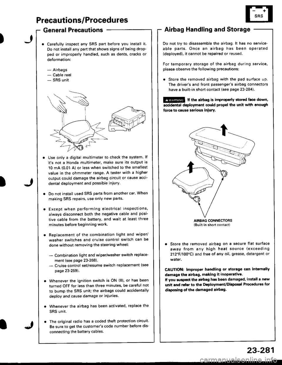
For temporary storage of the airbag during service,
please observe the following precautions:
. Store the removed airbag with the pad surface up.
The driver's and tront passenger's airbag connectors
have 8 built-in short contact (see page 23-284).
@ r the airbag is improp€rly storcd face down,
accidental deployment could propel the unit with enough
force to caus6 serious iniury.
AIRBAG CONNECTORS(Built-in short contact)
. Store the removed airbag on a secure flat surface
away from any high heat source (exceeding
212F110O'CI and free of any oil, grease, detergent or
water.
CAUTION: lmproper handling or storage can intornally
damags the airbag, making it inoperative.
1l you su3pocl the aitbag has been damaged, install a ncw
unit and rofEr to ths Deployment/Dilpolal Procedures for
dbposing of ihe damsged ailbag.
)
Page 1339 of 1681
Disconnecting the Airbag Connector(s)
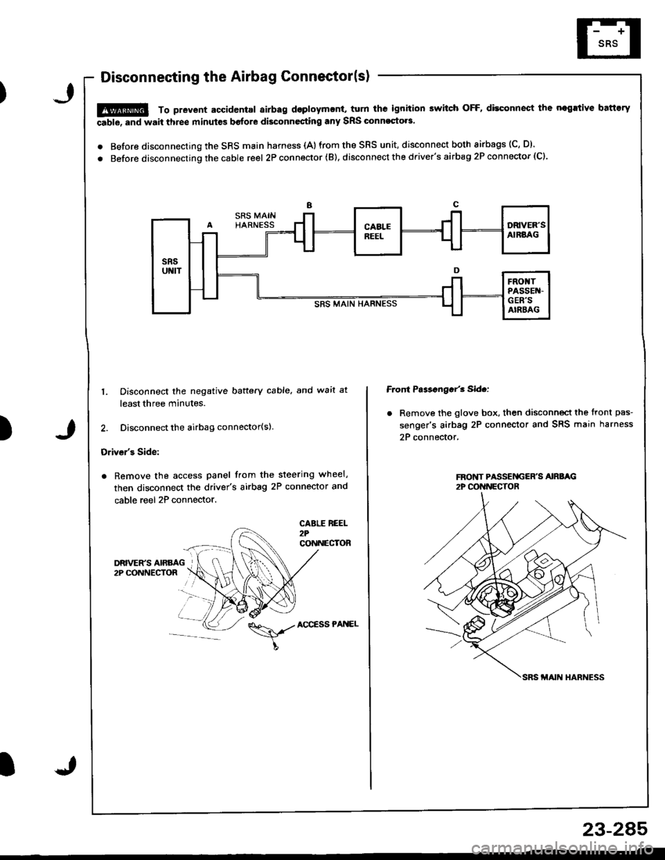
!@ To prevent accidental airbag dsploymcnt, turn ths ignition switch OFF, disconnect the negrtive battory
able, and wait three minut€s before disconnesting any SRS Glnnoqto.s.
. Before disconnecting the SRS main harness {A)from the SRS unit, disconnect both airbags (C, D).
. Before disconnecting the cable reel 2P con nector ( B). disconnect the driver's airbag 2P connector (C).
)
1. Disconnect the negative baftery cable. and wait at
least three minutes.
2. Disconnect the airbag connector(s).
Driver's Side:
. Remove the access panel from the steering wheel,
then disconnect the driver's airbag 2P connector and
cable reel 2P connector.
CABLE REEL2?CONNECTOR
Front Ps$sngar'3 Sid.:
. Remove the glove box. then disconnect the front pas-
senger's airbag 2P connector and SRS main harness
2P connector,
\,./AccEssPANEL
23-2A5
Page 1340 of 1681
Precautions/Procedures
Steering-related Precautions
Steering Wheel and Gable Reel Alignment
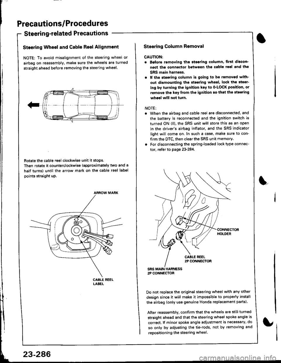
NOTE: To avoid misalignment of the steering wheel or
airbag on reassembly. make sure the wheels are turned
straight ahead before removing the steering wheel.
Rotate the cable reel clockwise unit it stops.
Then rotate it counterclockwise (approximately two and a
half turns) until the arrow mark on the cable reel label
points straight up.
ARROW MARK
23-286
Steering Column Removal
CAUTION:
. Before romoving the steoring column, lirst di3con-
nect ths connector bctwoen tho csble rsal and the
SBS main harneEs.
. lf the steeting column is going to be rsmoved with-
out dismounting the steering wheel, lock the steer-
ing by iurning the ignition k6y to o'LOCK position' or
remove tho key lrom thc ignition ro that the steering
wheel will not turn.
NOTE:
When the airbag and cable reel are disconnected, and
the battery is reconnected and the ignition switch is
turned ON (ll), the SRS unit will store this as an open
in the driver's airbag inflator, and the SRS indicator
light will come on. In such a case, make sure to con-
firm the DTC, then clear the SRS unit memory.
For disconnecting the spring-loaded lock type connec-
tor, refer to page 23-284,
SRS MAIN HARNESS2P CONNECTOR
Do not replace the original steering wheel with any other
design since it will make it impossible to properly install
the airbag {only use genuine Honda replacement parts).
After reassembly. confirm that the wheels are still turned
straight ahead and that the steering wheel spoke angle is
correct, lf minor spoke angle adjustment is necessary, do
so only by adjusting the tie-rods, not by removing and
repositioning the steering wheel.
L
Page 1343 of 1681
)
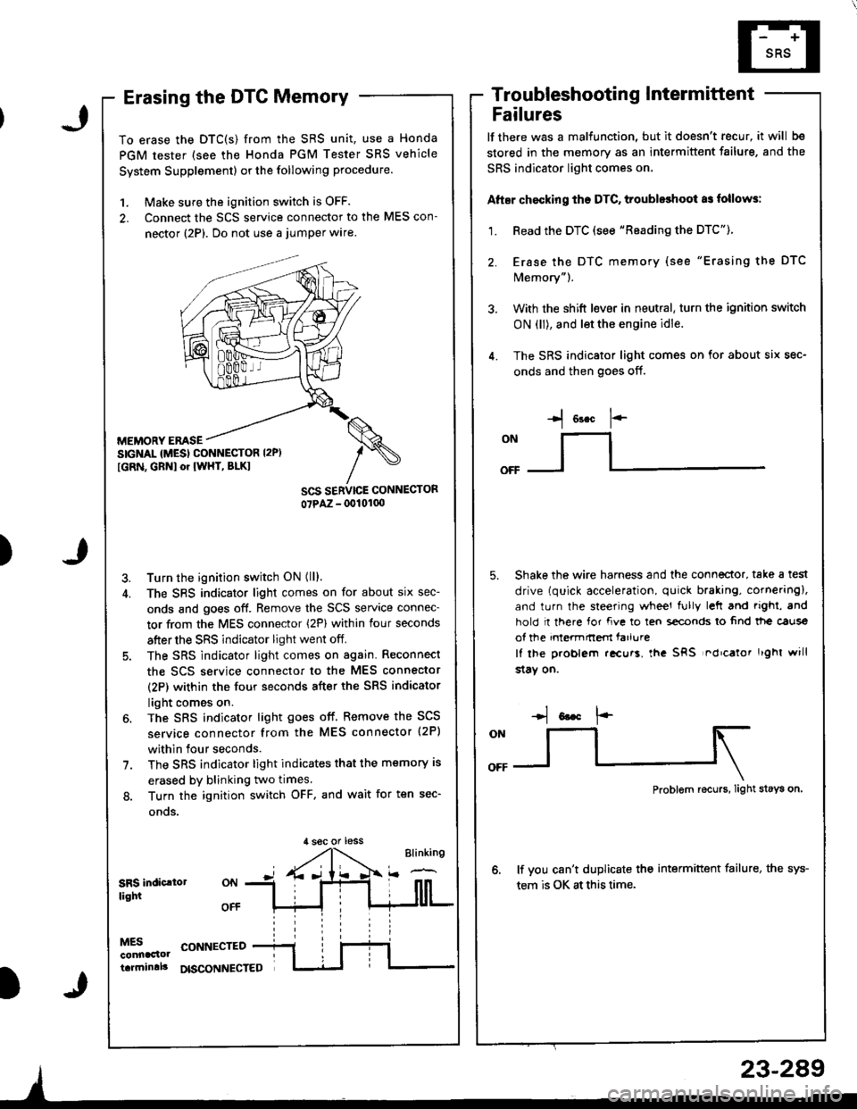
Erasing the DTC Memory
To erase the DTC(S) from the SRS unit, use a Honda
PGM tester (see the Honda PGM Tester SRS vehicle
System Supplement) or the following procedure.
1. Make sure the ignition switch is OFF.
2. Connect the SCS service connector to the MES con-
nector (2P). Do not use a jumper wlre.
MEMORY EMSESIGNAL {MESI CONNESTOR I2P)
[GRN, GBNI or IWHT, BLKI
Turn the ignition switch ON (ll).
The SBS indicator light comes on for about six sec-
onds and goes off. Remove the SCS service connec-
tor from the MES connector (2P) within four seconds
after the SRS indicator light went off.
The SRS indicator light comes on again. Reconnect
the scs service connector to the MES connector
(2P) within the four seconds after the SRS indicator
light comes on.
The SRS indicator light goes off. Remove the SCS
service connector from the MES connector (2P)
within four seconds.
The SRS indicator light indicates that the memory is
erased by blinking two times.
Turn the ignition switch OFF. and wait for ten sec-
onos.
Troubleshootin g Intermittent
Failures
lf the.e was a malfunction, but it doesn't recur, it will be
stored in the memory as an intermittent failure, and the
SRS indicator light comes on,
Atter chocking ths DTC, troubleshoot as follows:
1. Read the DTC (see "Reading the DTC").
2. Erase the DTC memory (see "Erasing the DTC
Memory").
3. With the shift l€ver in neutral, turn the ignition switch
ON (ll), and let the engine idle.
4. The SRS indicator light comes on for about six sec-
onds and then goes off.
I o"* 1--
ONllI
Shake the wire harness and the connector, take a test
drive (quick acceleration, quick braking, cornering),
and turn the steering wheel fully left and righi, and
hold I there for fve to ten s€conds lo 6nd tt|e caus€
of the intermnem farlure
It lhe problem .!curs, lha SRS nd'calor r'ghl will
$aY on.
,l soc or less
Problem recurs, Iight stays on
lf vou can't duplicate the intermittent failure, the sys-
tem is OK at this time.SRS indic.lollight
MESconnaclottarrninlll
CONNECTED
DISCONNECTED
23-289
Page 1371 of 1681
)
Airbag
Replacement
After a collision in which the airbags were deployed, the
airbag assemblies and the SRS unit must be replaced'
!!@ stole a removed sirbag with the pad sur'
ii6--up. tt tle sirbag i5 impropetly stored lace down,
accidental doploym€nt Gould propol tho unit with
enough lorce to cause serious iniury.
CAUTION:
. Do not install usad SRS parts from another vehicle'
When repairing, u3e only new SRS parB.
. Carefully inspsct the airbag befor€ you iGtall it Do
not install 8n airbag that shows signs of being
dlopped or improperly handled' such a3 dsnts,
cracks or defolmalion
. Always disconnact lhe airbag conneqtor{s) when the
harn$s is disconn€ctsd.
. Do not dislsembla or tlmp€r with thr sirbag
1. Make sure vou have th€ anti-theft code for the radro,
then write down the frequencies for the radio's pre-
set buttons.
2. Disconnect the battery negative cable, then discon-
nect the positive cable from the battery, and wait at
least three minutes.
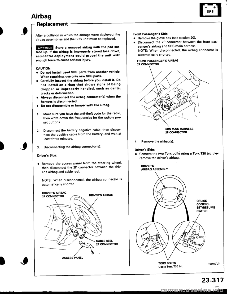
3. Disconnecting the airbag connector(s):
Driver's Side:
a Remove the access panel from the steering wheel,
then disconnect the 2P connector between the driv-
er's airbag and cable reel.
NOTE: When disconnected, the airbag connector is
automaticallY shorted.
)
23-317
2t @aa-gY(x
Front Pa3ienget's Sidel
. Remove the glove box (see section 20).
. Disconnect the 2P connector betwsen tha front pas-
senger's airbag and SRS main harness.
NOTE: When disconnected, the airbag conngctor is
automaticallY shoned
FBONT PASSENGER'S AIRBAG2P CONNECTOR
4. Remove the airbag(s):
Drivar's Side:
. Bemove the two Torx bolts using ! Torr T3O b{t, thGo
remove the driver's airbag'
DRIVER'SAIRBAG ASSEMBLY
CRUISECONINOLSET/RESUMEswtTcH
TORX BOLTSti3e a To T30 bit.(cont'd)
Page 1372 of 1681
Airbag
Replacement (cont'd)
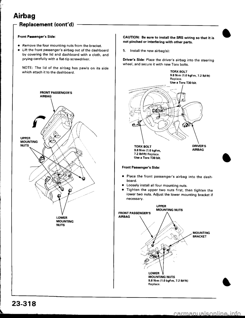
LOWERMOUNTINGNUTS
Fror|t P..s6nger'r Side:
. Remove the tour mounting nuts from the bracket.. Lift the front passenger's airbag out of the dashboard
by covering the lid and dashboard with a cloth. andprying carefully with a flat-tip screwdriver.
NOTE: The lid of the airbag has pawts on its sidewhich attach it to the dashboard.
CAUTION: Be sure to install the SRS wiring so that it isnot pincbed or interfering with other parts.
5. Install the new airbag(s):
Driver's Side: Place the driver's airbag into the steeringwheel. and secure it with new Torx bolts.
TORX BOLT9.8 N.m 11.0 kgf.m, 7.2 tbf.ft)
TORX BOLT9.8 N.m lt.o kgt m,7.2lbf,ftl Reptace.U36 a Torx T30 bit.
Front Paseenge/s Side:
Place the front passenger's airbag into the dash,bosrd.
Loosely install all four mounting nuts.Tighten the upper two nuts first, then tighten thelower two nuts. Adjust the lower mounting bracket ifnecessarv.
a
a
MOUNTING NUTS9.8 N.m (1.0 kgf.m. 7.2 lb{.ftlReplace.
Us€ a Torx T30 bit.
MOUNTING NUTS
Page 1373 of 1681
I
I
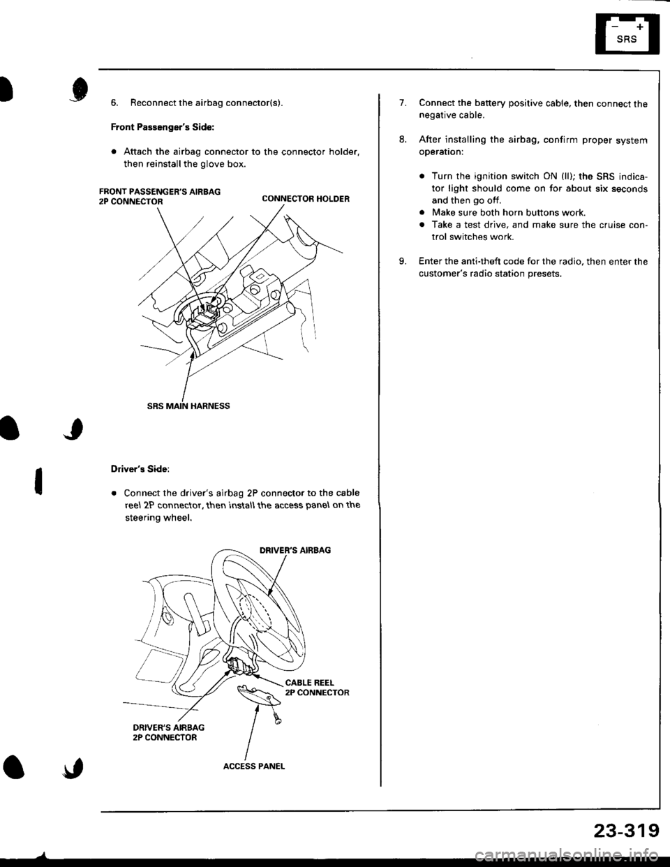
6. Reconnect the airbag connector(s).
Front Passenger's Side:
. Attach the airbag connector to the connector holder.
then reinstallthe glove box.
CONNECTOR HOLDER
Driver's Side:
. Connect the driver's airbag 2P connector to the cable
reel 2P connector, then rnstall the access panel on the
steering wheel.
\,
23-319
7.Connect the baftery positive cable, then connect thenegative cable.
After installing the airbag, confirm proper system
operal|on:
. Turn the ignition switch ON (ll); the SRS indica-
tor light should come on for about six seconds
and then go off.
. Make sure both horn buttons work.
. Take a test drive, and make sure the cruise con-
trol switches work.
Enter the anti-theft code for the radio. then enter the
customer's radio station presets,
9.