Page 1342 of 1681
v
-t f--.l r --1 f-M.in cod. {11 S!b{od. (2}
oTcr2
-l F --{ FMain cod. (l) Sub-cod.11).--.Y-oTc r-rThnd'm6r.@6m
2
ON
light sl.ys on h ct36 or
Troubleshooting
Reading the DTC (cont'd)
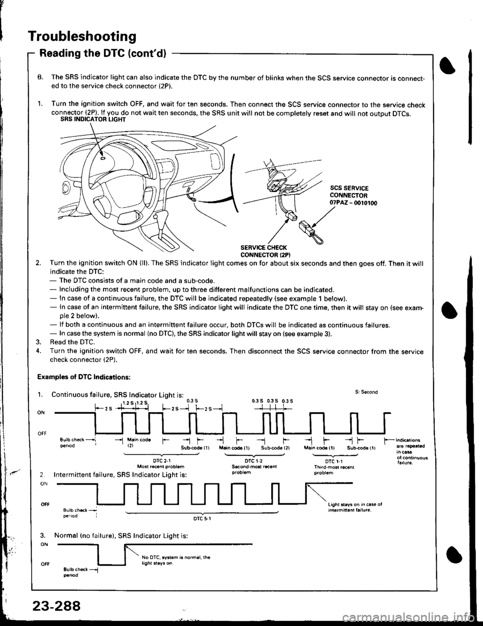
B. The SRS indicator light can also indicate the OTC by the number of blinks when the SCS service connector ts connect-ed to the service check connector (2P).
1. Turn the ignition switch OFF, and wait for ten seconds. Then connect the SCS service connector to the service checkconnector (2P). lf you do not wait ten seconds, the SRS unit will not be completelv reset and will not outout DTCS.SRS INDICATOR LIGHT
scs SERV|CECONI{ECTOR- (x)l01(x)
SERVICE CHECKCONNECTOR (2PI
2. Turn the ignition swilch ON (ll). The SRS indicator light comes on for about six seconds and then goes off. Then it will
indicate the DTC:- The DTC consists of a main code and a sub-code.- Including the most recent problem, up to three different malfunctions can be indicated.- ln case of a continuous failure, the DTC will be indicated repeatedly (see example 1 below).- In case of an intermiftent failure, the SRS indicator light will indicate the DTC one time. then it will stay on (see exarn-ple 2 beiow).- lf both a continuous and an intermittent failure occur, both DTCS will be indicated as continuous failures.- In case the system is normal (no DTC), the SRS indicator light will stay on {see example 3).
3. Read the DTC.
4. Turn the ignition switch OFF, and wait for ten seconds. Then disconnect the SCS service connector from the servicecheck connector (2P),
Examples ol DTC Indications:
L Continuous failure, SRS Indicator Light is:0.3 s 0.3s 0.3 s-]-]-l-t-
07?M
(S./'
\
-l Mlin cod. r
orc 2-1Mo3t r.cant probt.m
Intermittent failure, SRS Indicator Light is:
Normsl (no failure), SRS Indicator Light is:
oTc 5,r
Page 1343 of 1681
)
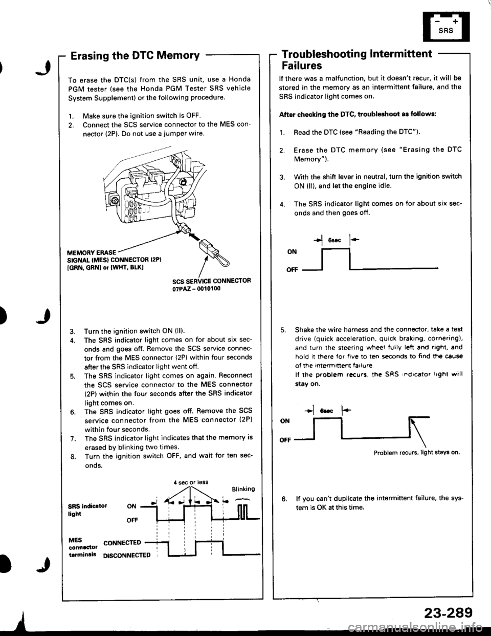
Erasing the DTC Memory
To erase the DTC(S) from the SRS unit, use a Honda
PGM tester (see the Honda PGM Tester SRS vehicle
System Supplement) or the following procedure.
1. Make sure the ignition switch is OFF.
2. Connect the SCS service connector to the MES con-
nector (2P). Do not use a jumper wlre.
MEMORY EMSESIGNAL {MESI CONNESTOR I2P)
[GRN, GBNI or IWHT, BLKI
Turn the ignition switch ON (ll).
The SBS indicator light comes on for about six sec-
onds and goes off. Remove the SCS service connec-
tor from the MES connector (2P) within four seconds
after the SRS indicator light went off.
The SRS indicator light comes on again. Reconnect
the scs service connector to the MES connector
(2P) within the four seconds after the SRS indicator
light comes on.
The SRS indicator light goes off. Remove the SCS
service connector from the MES connector (2P)
within four seconds.
The SRS indicator light indicates that the memory is
erased by blinking two times.
Turn the ignition switch OFF. and wait for ten sec-
onos.
Troubleshootin g Intermittent
Failures
lf the.e was a malfunction, but it doesn't recur, it will be
stored in the memory as an intermittent failure, and the
SRS indicator light comes on,
Atter chocking ths DTC, troubleshoot as follows:
1. Read the DTC (see "Reading the DTC").
2. Erase the DTC memory (see "Erasing the DTC
Memory").
3. With the shift l€ver in neutral, turn the ignition switch
ON (ll), and let the engine idle.
4. The SRS indicator light comes on for about six sec-
onds and then goes off.
I o"* 1--
ONllI
Shake the wire harness and the connector, take a test
drive (quick acceleration, quick braking, cornering),
and turn the steering wheel fully left and righi, and
hold I there for fve to ten s€conds lo 6nd tt|e caus€
of the intermnem farlure
It lhe problem .!curs, lha SRS nd'calor r'ghl will
$aY on.
,l soc or less
Problem recurs, Iight stays on
lf vou can't duplicate the intermittent failure, the sys-
tem is OK at this time.SRS indic.lollight
MESconnaclottarrninlll
CONNECTED
DISCONNECTED
23-289
Page 1344 of 1681
Troubleshooting
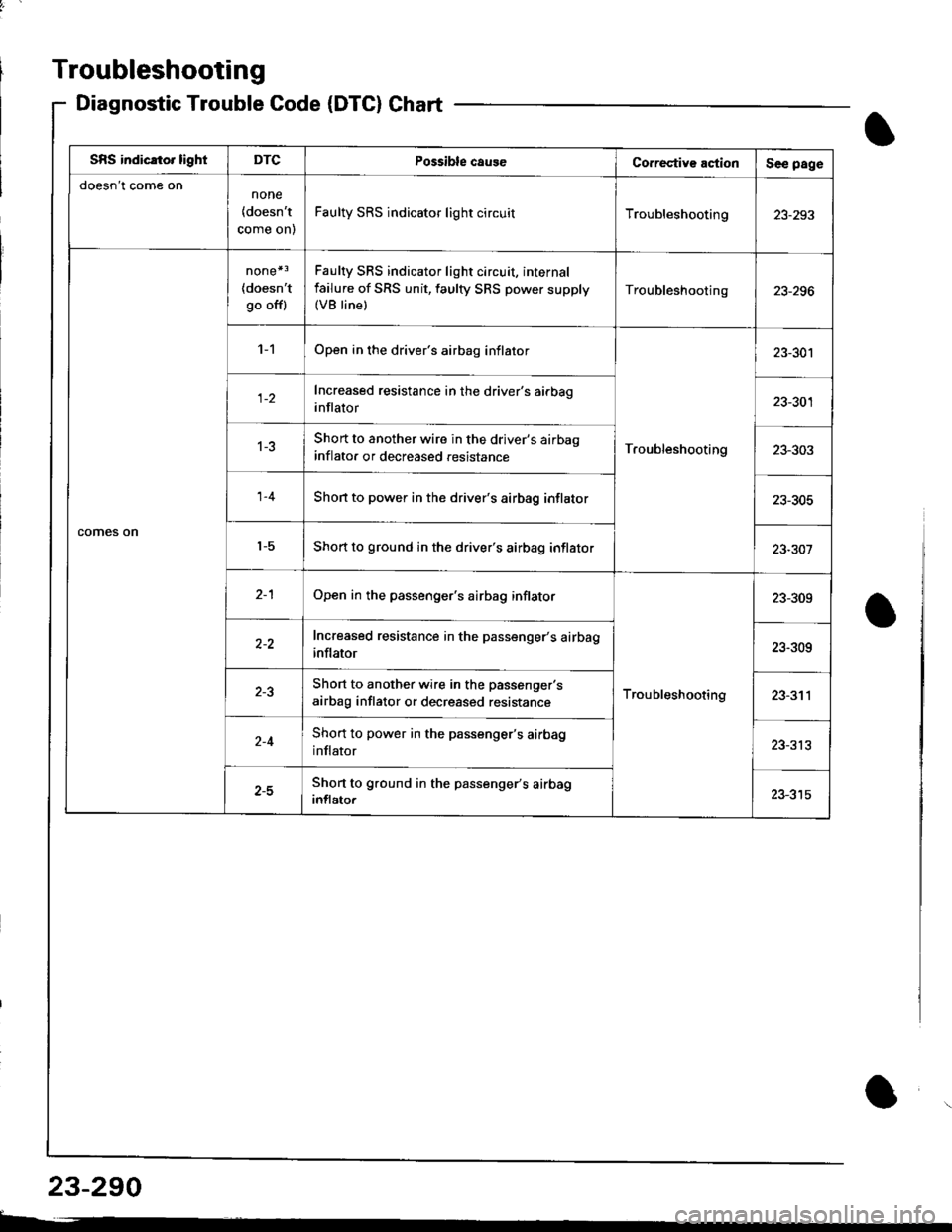
Diagnostic TroubleCode(DTC}Chart
SBS indicato. lightDTCPossible caug€Co.rective actionSee page
doesn't come onnone
{doesn't
come on)
Faulty SRS indicator light circuitTroubleshooting23-293
comes on
none*3
{doesn'tgo off)
Faulty SRS indicator light circuit, internal
failure of SRS unit, faulty SRS power supply(VB line)
Troubleshooting
'l -1Open in the driver's airbag inflator
Troubleshooting
23-301
Increased resistance in the driver's airbag
inflator23-301
1-3Short to another wire in the driver's airbao
inflato. or decreased .esistance23-303
1-4Shon to power in the driver's airbag inflator23-305
't-5Short to ground in the driver's airbag inflator23-301
2-1Open in the passenger's airbag inflator
Troubleshooting
23-309
Increased resistance in the passenger's airbag
inflator23-309
Short to another wire in the passenger's
airbag inflator or decreased resistance23-311
Short to power in the passenger's airbag
inflator23-313
z-JShort to ground in the passenger's airbag
inflator
23-290
t-
I
Page 1346 of 1681
Troubleshooting
SRS Indicator Light Wire Connections
SRS Indicator Light Power Circuit
To UNDER-DASHFUSE/RELAY BOX2OP CONNECTOB
SRS Indicator Light Control Circuit
To SBS UNIT
iI
SRS MAIN HABNESS
C55'1, C557 : WIRE SIDE OF FEMALE TERMINALS
DASHBOARD WIRE HARNESS
MAIN WIRE HARNESS
C557 -+ To GAUGE ASSEMBLY
CiP7, C449 : TERMINAL SIDE OF MALE TERMINALSC553, CEo1. C802, C804: WIBE SIDE OF FEMALE TEFMINALS
DASHBOAND WIREHARNESS
To UNOEF-DASHFUSE/RELAY BOX2P CONNECTOR
C427 : MAIN WIRE HARNESS 3P CONNECTORC/r49 : MAIN WIBE HARNESS 16P CONNECTORC551 : DASHSOARD WIRE HARNESS 2Op CONNECTORC553 : DASHBOARD WIFE HARNESS t6P CONNECTORCssT : OASHBOARD WlnE HABNESS SP CONNECTOB
To GAUGE ASSEMBLY
C801 : SRS MAIN HARNESS 2P CONNECTOBC802 : SRS MAIN HARNESS 3P CONNECTORC804: SRS MAIN HAFNESS 18P CONNECTOR
BLU
Page 1347 of 1681
The SRS Indicator Light Doesnt Come On
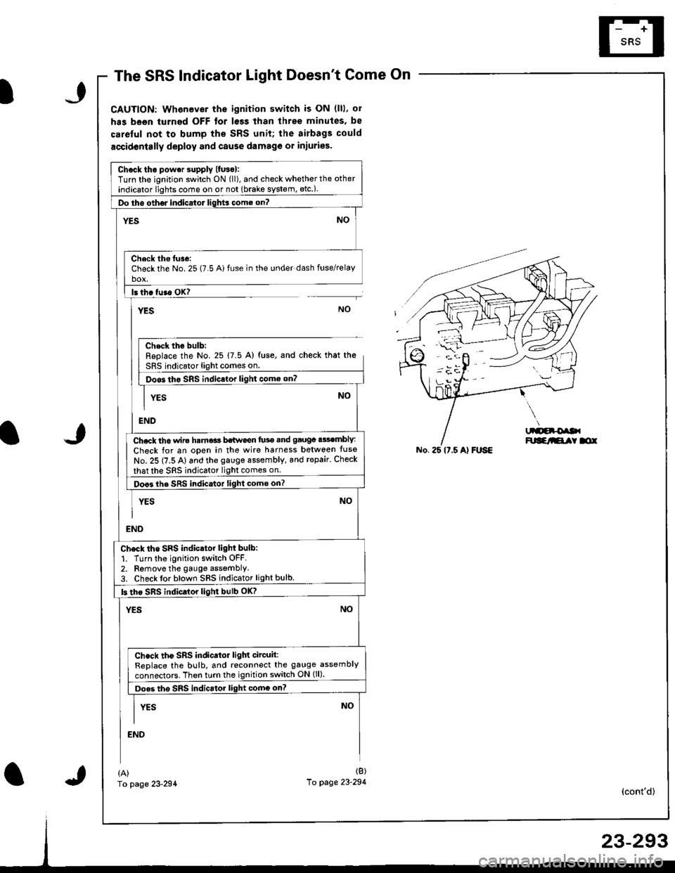
CAUTION: Whenever the ignition switch is ON (lll, ol
has been turned OFF tor lsss than three minutes. be
careful not to bump the SRS unit; the airbags could
accidentslly deploy and cause damage or iniuries.
Chcck tho power supply lfuso):Turn the ignition switch ON (ll), and check whether the other
indicator lights come on or not (brake system, etc.).
Do tho oth6J indicator ligh$ come on?
NO'ES
Check ths tuse:Check the No. 25 (7.5 Ai fuse in the under dash fuse/relayho!
ls th. tu.o OK?
YESNO
Chsck the bulb:Replace the No. 25 17.5 A) fuse, and check that the
SRS indicator light comes on.
Doos tho SRS indic.lor light como on?
YES
END
Ch.ck th6 wir€ ham€ls b€twoen fu3e snd gauge .3sembly:
Check for an open in the wire harness belween tuse
No. 25 (7.5 A) and the gauge sssembly, and repair. Check
that the sRS indicator light comes on.
Doo3 the SRS indicator light come on?
YES
NO
NO
END
Ch6ck tho SRS indicator light bulb:
1. Turn the ignition switch OFF.2. Remove the gauge assemblY3. Check tor blown SRS indicator light bulb.
b tho sRs indicrlor light bulb oK?
YESNO
Check tho SRS indicator ligln circuit:ReDlace the bulb, and reconnect the gauge assembly
connectors. Then turn the ignition switch ON (ll).
Do.s tho SRS indicrtor light comG on?
I vrs NoII
END
No. 25 lt.5 Al FUSE
{A)fo page 23-294
(B)
10 page 23-294(cont'd)
Page 1348 of 1681
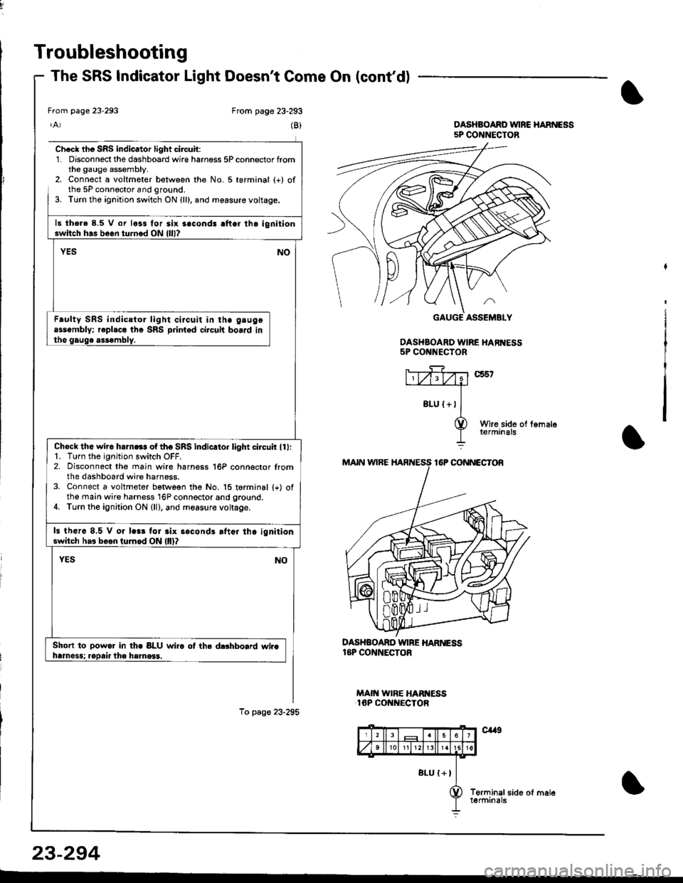
Troubleshooting
The SRS Indicator Light Doesnt Come On (cont'd)
From page 23-293
(B)
Ch.cl th. SRS indicator light circuit:1. Disconnect the dashboard wire harness 5P connector fromthe gauge assembly.2. Connect a voltmeter belween the No. 5 terminal (+) ofthe 5P connoctor and ground.3. Turn the ignition switch ON {ll}, and measure voltage.
ls the.e 8.5 V or less for six 3econd! rflor lho ignitionswitch h.s be6n turned ON llll?
YESNO
Faulty SRS indicstor light circuit in ihe gtugoassembly; r€pl.co tho SRS printed circuit board inthe gaug. assembly.
Check the wiro ham.ss of tho SRS indicltor light circuh ll l:1. Turn the ignition switch OFF.2. Disconnect the main wire harn€ss 16P connector lromthe dashboard wire harness.3. Connect a voltmeter betlveen the No. 15 torminal {+) ofthe main wire harness 16P connector and ground.4. Turn the ignition ON (ll), and measure voltage.
13 there 8,5 V or lc.r tor 3lx s.condr lftor th. ignitionswitch h.3 boon tuJnod ON llll?
Short to powor In th. BLU wiro ot ths d$hbolrd whahrmess; ropair the hsmo*1.
To pag€ 23-295
DASHBOARD WINE HAR ESS16P CONNECTOR
MAIN WIRE HARI{ESS16P CONNECTOR
From page 23-293
DASHBOAND VUIRC HARNESS5P CONNECTOB
DASHBOARD WIRE HARI{ESS5P CONNECTOR
23-294
Page 1350 of 1681
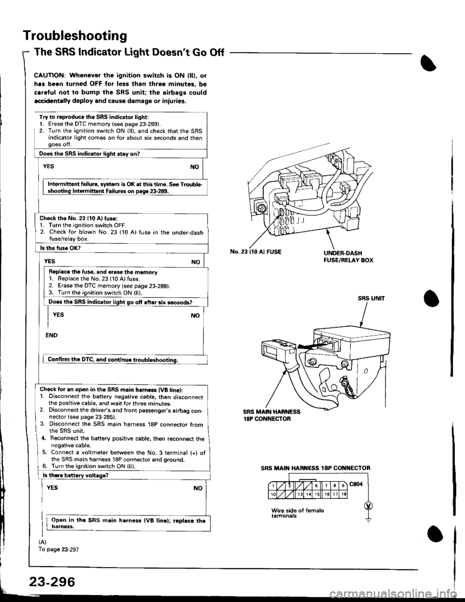
Troubleshooting
The SRS Indicator Light Doesnt Go Off
CAUTIOi{: Whenever the ignition switch is ON (ll). or
h.s bGGn turned OFF for less than three minutes. be
crrclul noi to bump the SRS unit; the airbags could
lcci{tcntrlly deploy and cause damage or iniuries.
(A)
1o page 23-297
Try to reproduce the SRS indic.tor l;ght;l. Erase the DTC memory (see page 23-289).2. Turn the ignition switch ON (ll), and check that the SRSandicator light comes on lor about six seconds and thenooes off,
Ooes the SRS indicetor light stay on?
NOYES
Intermittc t failu.e, sydem is OK dt this time. Sec Troublo-shooting lntermitteirt Failuros on p.qe 23-28!1.
Check tho No. 23 {10 A) fuse:1. Turn the ignition switch OFF-2. Check for blown No. 23 110 A) fuse in the unde.dashfuse/relay box.
ls the luse OK?
YESNO
Roplsce the f!se, and eresc the memory1. Replace the No. 23 (10 Alfuse.2. Erase the DTC memory (see page 23-289).3. Turn the ignition switch ON (ll).
Does th6 SRS indicator light go off after rix socond6?
I YEs No
I
ENO
Contilm the DTC, and continuo troubleshooting.
Check tor an open in ths SRS main hlrna3r (VB tinc):1- Disconnect the battery negative cable. thon disconnectthe positive cable, and wait tor three mrnures.2. Disconnect the driver's and front passenger's airbag con-nector (see page 23 285).3. Disconnect the SRS main harness 18P connector fromthe SRS unit.a. Reconnect the battery positive cable, then reconnect thenegative cable.5. Connect a voltmeter between the No. 3 terminal (+) otthe SRS main harness 18P connector and ground.6. Turn the ignition switch ON {ll).
ls th.re bettery vohaqe?
YES
Open in th. SRS msin h.rness (VB linc); roptrca tha
NO
No.23110 Al FUSEUNOER.DASHFUSE/RELAY AOX
SRS UNIT
SRS MAIN HARI{ESS 18P COI{I{ECTOR
Page 1351 of 1681
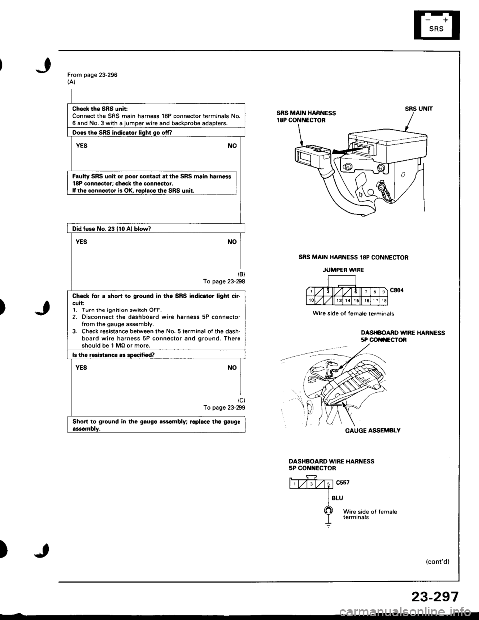
Chcck tho SRS unh:Connect the SRS main harness 18P connector terminals No.6 and No. 3 with a jumper wire and backprobe adapters.
Oos6 th6 SRS indicator liqhi so offl
YESNO
Faulty SRS unit or poor contact at the SRS main hamoi318P connector; check lhe connactor.Ittho connector i3 OX, replaco the SRS unit.
Did fuse No.23 {10 Al blow?
YESNO
(B)
To page 23-298
Chock tor a short to ground in thc SRS indic.tor light ci.-cuit:1. Turn the ignition switch OFF.2. Disconnect the dashboard wire harness 5P connectorfrom the gauge assembly.3. Check resistance between the No. 5 terminal of the dash-board wire harness 5P connector and ground. Thereshould be 1 MO or more.
ls the resistance as apocifiad?
YESNO
{c)To page 23-299
Short to ground in tho gauga aatambly; raplace tho gaugeasscmblY.
From page 23-296(A)
SRS MAIN HARNESS 18P CONNECTOR
JUMPER WIRE
)
oasrSoAno unRE HARt{Ess5P @ilFCTOn
GAUGE ASSEMBLY
DASHAOARD WIBE HARNESS5P CONNECTOR
ffiv;1"u*---.--a
] sru
O wire side of female
I terminals
)(cont'd)
UNITsRs
Wire side of female lerminals
f,t
r
23-297