Page 790 of 2189

Symptom-to-Component Chart
Hydraulic System (cont'dl
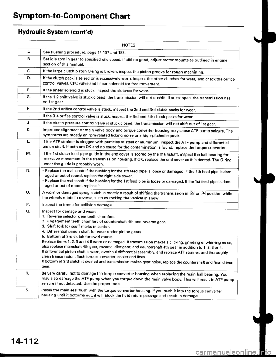
G.
n,
set idle rpm in gear to specified idle speed. lf still no good, adjust motor mounts as outlined in enginesection of this manual.
lf the clutch pack is seized or is excessively worn. inspect the other clutches for wear, and check the orificecontrol valves, CPC valve and linear solenoid for free movement.
lf the linear solenoid is stuck, inspect the clutches for wear.
lmproper alignment or main valve body and torque converter housing may cause ATF pump seizure. Thesymptoms are mostly an rpm-related ticking noise or a high-pitched squeak.
lf the l st clutch feed pipe guide in the end cover is scored by the mainshaft, inspect the ball bearing forexcessive movement in the transmission housing. lf oK, replace the end cover as it is dented. The o-rinounder the guide is probably worn.
Replace the mainshaft if the bushing for the 4th feed pipe is loose or damaged. lf the 4th feed pipe is danFaged or out of round, replace the right side cover.
Replace the mainshaft if the bushing for the 1st feed pipe is loose or damaged. lf the 1st feed pipe is darn-aged or out of round, replace it.
A worn or damaged sprag clutch is mostly a result of shifting the transmission inthe wheels rotate in reverse, such as rocking the vehicle in snow.
or E position while
Inspect for damage and wear:
1. Reverse selector gear teeth chamfers.
2. Engagement teeth chamfers of countershaft 4th and reverse gear.
3. Shift fork for scuff marks in center.
4. Differential pinion shaft for wear u nder pin ion gears.
5. Bottom of 3rd clutch for swirl marks.
Replace items 1,2,3 and 4 if worn or damaged. lf transmission makes a clicking, grinding orwhirring noise,also replace mainshaft 4th gear, reverse idler gear. and countershaft 4th gear in addition to 1, 2, 3 or 4.lf differential pinion shaft is worn, overhaul differential assembly, and replace ATF strainer, and thoroughlyclean transmission, flush torque converter, cooler and lines.lf bottom of 3rd clutch is swirled and transmission makes gear noise, replace the countershaft and final drivengear.
Be very careful not to damage the torque converter housing when replacing the main ball bearing, you
may also damage the ATF pump when you torque down the main valve body. This will result in ATF pumpseizure if not detected. Use the oroper roors.
Install the main seal flush with the torque converter housing. lf you push it into the torque converterhousing until it bottoms out, it will block the fluid return passage and result in damage.
See flushing procedure, page 14-187 and 188.
lf the large clutch piston O-ring is broken, inspect the piston groove for rough machining.
lf the l-2 shift valve is stuck closed, the transmission will not upshift. lf stuck open, the transmission hasno 1st gear.
lf the znd orifice control valve is stuck. inspect the 2nd and 3rd clutch oacks for wear.
lf the 3-4 orifice control valve is stuck, inspect the 3rd and 4th clutch oacks for wear.
lf the clutch pressure control valve is stuck closed, the transmission will not shift out of 1st gear.
lf the ATF strainer is clogged with particles of steel or aluminum, inspect the ATF pump and differentialpinion shaft. lf both are OK and no cause for the contamination is found, replace the torque converter.
Inspect the frame for collision damage.
14-112
Page 791 of 2189

Road Test
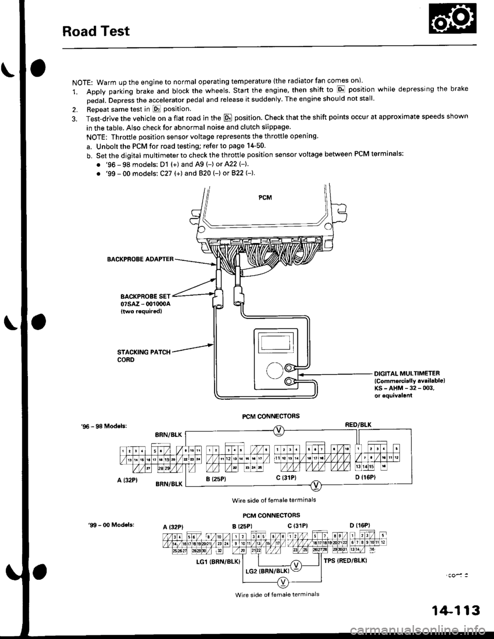
NOTE: Warm up the engine to normal operating tem peratu re (the rad iator fan comes on )'
1. Apply parking brake and block the wheels. Start the engine, then shift to E position while depressing the brake
Dedal, Depress the accelerator pedal and release it suddenly. The engine should not stall'
2. Repeat same test in E Position.
3. Test-drive the vehicle on a flat road in the E position. Check that the shift points occur at approximate speeds shown
in the table. Also check for abnormal noise and clutch slippage.
NOTE: Throttle position sensor voltage represents the throttle opening
a. Unbolt the PCM for road testing; refer to page 14-50.
b. Setthedigital multimeter to check the th rottle position sensor voltage between PCM terminals;
. '96 - 98 models: D1 {+) and A9 (-) or 422 (-}.
. '99 - 00 models: C27 (+) andB20t-) orB22{-}.
BACKPROBE ADAPTER
BACKPROBE SET07sAz - 001oq)A{two requiredl
DIGIIAL MULTIMETERlCommercially available)KS-AHM-32-003,or equivalenl
'96 - 98 Modelsr
Wire side ol temale terminals
PCM CONNECTORS
B t25Pl c (31P)
LG1 IBRN/BLK)
I (25P1c (31P}
A t32PtD (16P)
Wire side ol female terminals
'9!t - 00 Models:
1+113
Page 794 of 2189

Stall Speed
Test
CAUTION:
. To prev€nt transmission damage, do not t6st stall speed for more than ro sgconds at a time.. Do not shift the levor while raising the engine speed.. Bo sule lo remove the pressure gauge betoro testing stall speed.
'1. Engage the parking brake, and block the front wheels.
2. Connect a tachometer to the engine, and start the engine.
3. Make sure the Ay'C switch is OFF.
4. After the engine has warmed up to normal operating temperature (the radiator fan comes on). shift into E position.
5. Fully depress the brake pedal and accelerator for 6 to g seconds, and note engine speed.
6. Allow two minutes for cooling, then repeat the test in @ and @ positions.
NOTE:
. Stall speed tests should be used for diagnostic purposes only,. Stall speed should be the same in o., E and E positions.
Stall Spsed RPM:
Specification: 2.700 rpm
Service Limit: 2,550 - 2,850 rDm
TROUBLEPROBABLE CAUSE
. Low fluid level or ATF pump outDur. Clogged ATF strainer. Pressure regulator valve sluck closeo. Slipping clutch
. Slippage of 4th ctutch
. Slippage of 2nd clutch
. Slippage of lst clut"tr or. t"t g""io*-*"y "lut"h
Stall rpm high in D., E and E positions
Stall rpm high in El position
Stall rpm high in E posirion
Stall rpm high in E position
Stall rpm low in LDa . El and E positrons. Engine output low. Torque converter one-way clutch slipping
14-116
Page 799 of 2189
2nd, 3rd and 4th Clutch Pressure Measurement
1. Set the parking brake, and block both rear wheels securely'
2. Start the engine, and run it the engine at 2,000 rpm'
3. Shift to E position, then measure 2nd clutch pressure
4. Shiftto El position, then measure3rd clutch pressure
5. Shift to E position, then measure 4th clutch pressure'
6. Shift to E position, then measure 4th clutch pressure'
INSPECTION HOI'E(Marked with "3")
2ND CLUTCH PR€SSURE
INSPECTION HOLE
FLUID PRESSURE
standard I sorviqe LimitPRESSURESHIFT LEVER
POStT|()NSYMPTOMPROBABLE CAUSE
2nd ClutchtrNo or low 2nd
pressure
2nd Clutch800 - 850 kPa
(8.2 - 8.7 kgflcm'�,
120 - 120 psi)
760 kPa
(7.7 kgf/cm'�, 110 Psil
3rd ClutchtrNo or low 3rd
pressure
3rd Clutch8'�10 - 860 kPa
(8.3 - 8.8 kgt/cm',
120 - 130 psi)
760 kPa
(7.8 kgt/cm', 110 Psi)
4th clutchp.lNo or low 4th
presSure
4th clurch
EServo Valve or 4th
Clutch
1+121
Page 800 of 2189
Transmission
Removal
@Maks sure lifts, iacks and safety stands are placedproperly, and hoist bracket ate aftached to the cor_rec{ position on the engine lsee section 1).Apply parking brake and block rear whoels so vehiclewill not roll off stands and fall on you while workingunder it.
CAUTION: Use tender covers to avoid damaging paint-ed surfaces.
1, Disconnect the battery negative (_) terminal fromthe battery, then remove the positive (+) terminal.
2. Remove the intake air duct.
D16Y7 engins:
Remove the intake air duct and resonator.
D16Y8 engine:
Remove the intake air duct and the air cleaner hous-ing assembly,
3. Remove the starter cables and cable holder fromthe starter motor.
MOTOR CABLE
MOTOR CABLE
14-122
4. Remove the transmission ground cable, and discon_nect the lock-up control solenoid connector.
LOCK.UP CONTROLSOLENOID CONNECTOR
5, Disconnect the vehicle speed sensor (VSS) connec_tor and the countershaft speed sensor connector.
VEHICLE SPEED
Page 845 of 2189
Backlash lnspection
1. Place differential assembly on V-blocks and install
both axles.
Check backlash of both pinion gears
Standard {Now): 0.05 - 0.15 mm {0.002 - 0.006 in)
lf backlash is out of tolerance, replace the differen-
tial carrier.
Bearing Replacement
NOTE: Check bearings for wear and rough rotation. lf
bearings are OK, removal is not necessary.
1, Remove bearings using a bearing puller.
BEARING PULLER(Commerci6lly available)
2. Install new bearings using the specialtool as shown.
14-167
Page 866 of 2189
Transmission
17.
Cooler Flushing (cont'dl
Make sure the transmission is in the E position.
Fill the transmission with ATF, and run the enginefor 30 seconds or until approximately 0.95 f (1.0 USqt.,0.8 lmp qt.) is discharged.
Remove the drain hose, and reconnect the coolerreturn hose to the transmission (see page l4-192).
Refill the transmission with ATF to the oroDer level(see page 14-118).
18.
19.
b
14-18A
TOOL MAINTENANCE
1. Empty and rinse after each use. Fill the can with waterand pressurize the can. Flush the discharge line toensure that the unit is clean.
2. lf discharge liquid does not foam, the orifice may beblocked.
3. To clean, disconnect the plumbing from the tank atthe large coupling nut.
ORIFICE
GRT{G
Remove the in-line filter from the discharge side andclean if necessary.
The fluid orifice is tocated behind the filter.Clean it with the pick stored in the bottom of thetank handle, or blow it clean with air. Securelvreassemble all Darts.
FILLER CAP
Page 920 of 2189

Troubleshooting Flowchart - Vehicle Speed Sensor (VSS)
NOTE: Record all freeze data before you troubleshoot'
Po$rible Ctuse
. Disconnected vehicle speed
sensor (VSS) connectol. Short or open in VSS wire' Faulty VSS
@. Make sure lifts, iacks, and sal€tY stands are placed properly lsoe section 1)'
. Set the parking brake securelv, and block the rear wheels'
. iacr upile rront or the vehicle, and support it with safety st'nds'
TCM CONNECTORS
Wire side of female terminals
. OBD ll Scan Tool indicates Code
P1791.. Setf-diagno3is E indicato. light
blinks tour times.
Refer to seclion 23 for vehicle
soeed sensor IVSSI test
Check the VSS Voltage:
1. Raise the vehicle2. Shift the transmission to lEposrtlon.3. Disconnect the A (26P) and B(22P) connectors from the
TCM.4. Turn the ignition switch ON {ll).
5. Rotate the front wheel and
check for the voltage between
the 85 and 413 or A26 termi-
nals. Block the other wheel so
at does not turn
Check for oP€n in the wire
between the 85 terminal and the
vehicle speed sensor {VSS}. lf
wire is OK, check the vSS (see
soction 23).
Does0Vandapprox 5 V or more
appear alternatelY?
Check for loos€ TCM connedors
lI nec€ssary, substitute a known'
good TCM and recheck.
14-243