Page 651 of 2189
Disassembly
1. Remove the ball bearing using a bearing puller as
shown.
BEABING PULLER
BALL BEARING
CAUTION: Remove the synchro hubs using a ptess
and the sts€l blocks as shown. Use of a i8w'type
puller can cause damage to th€ gear teeth.
Support sth gear on steel blocks, and press the
mainshaft out of the sth synchro hub, as shown.
3. Support 3rd gear on steel blocks, and press the
mainshaft out of the 3rd/4th svnchro hub, as shown.
13-71
Page 653 of 2189

Reassembly
CAUTION:
. Press the 3rd/4th and the 5th synchro hubs on the
mainshaft without lubrication.
o When installing the 3rd/,lth and the sth synchro
hubs, support the mainshaft on steel blocks, and
installthe synchro hubs using a prsss.
. Install the 3rd/4th and the sth synchro hubs with a
maximum plessur€ of 19.6 kN (2,000 kg, 14,466 lbl.
NOTE: Refer to page 13-67 for reassembly sequence.
1, Support 2nd gear on steel blocks, then install the
3rd/4th synchro hub using the special tools and a
press, as snown.
NOTE:
. After installing. check the operation of the
3rd/4th synchro sleeve and hub.
. Assemble the 3rd/4th synchro hub and sleeve
together betore installing them on the mainshaft.
Closed end
3RD/4THSYNCHRO HU3DBIVER, 10 mm l.O.07746 - 00301U)
/ lrrlcHlileNr. ss .- t.o.07746 - 0030,100
l.
3RD/{THSYNCHROSLEEVE
2ND GEAR
2. Install the sth synchro hub using the special tools
and a press as snown.
DRIVER, {0 mm l.O.07746 - 0030100
ATTACHMENT,35 mm LD.
sTH SYNCHRO HUB
07716 - 0030,100
3. Install the angular ball bearing using the special
tools and a press as shown.
PRESS
+
DRIVER, 40 mm LD.0?7a6 - It030100
Page 656 of 2189
Gountershaft Assembly
Disassembly
1. Securely clamp the countershaft assemblv in a
bench vise with wood blocks.
2. Raise the locknut tab from the groove in the coun-
tershaft, then remove the locknut and the spring
washer.
Remove the ball bearing using a bearing pulle. asshown.
BEARING PULLER
BALL BEARING
13-76
4, Remove the bearing outer race, then remove theneedle bearing using a bearing puller as shown.
BEARING PULLEF
BEARING
CAUTION: Romove the gears using a pr63 and the
stesl blocks as shown, Use of a ,aw-typo puller can
cause damage lo lhe gear tooth.
Support 4th gear on steel blocks, and press thecountershaft out of sth and 4th gears, as shown.
sTH GEAF
{TH GEAR
.(
a
ItI
Page 658 of 2189

Gountershaft Assembly
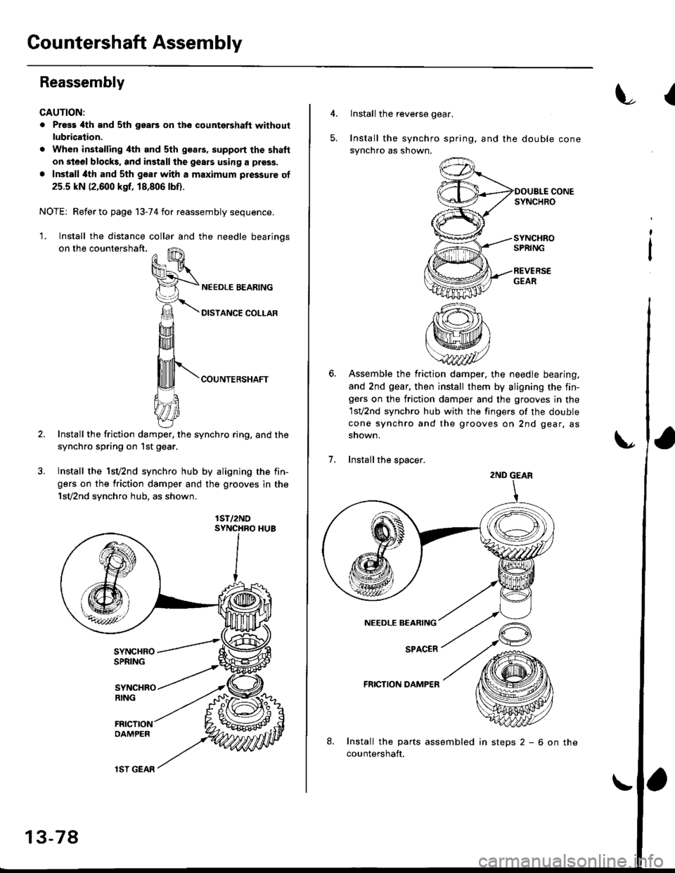
Reassembly
CAUTION:
. Pross 4th and sth gears on the countershaft without
lubrication.
. When installing ilth and sth geafs, support the shaft
on steel blocks, and install the gears using a press.
. Install ilth and sth gear with a maximum pressure of
25.5 kN (2,600 ksf, 18,806lbf).
NOTE; Refer to page 13-74 for reassembly sequence.
'1. Install the distance collar and the needle bearinos
on the countershaft.
COUNTERSHAFT
Install the friction damper, the synchro ring, and the
synchro spring on 1st gear.
Install the 1sv2nd synchro hub by aligning the fin-
gers on the friction damper and the grooves in the
1sv2nd synchro hub, as shown.
lST/2NO
13-78
lSI GEAR
insteps2-6onthe
{
4.lnstall the reverse gear.
Install the synchro spring. and the double cone
synchro as shown.
Assemble the friction damper, the needle bearing,
and 2nd gear, then install them by aligning the fin-gers on the friction damper and the grooves in the
1sv2nd synchro hub with the fingers of the double
cone synchro and the grooves on 2nd gear, as
snown.
Installthe spacer.
FRICTION DAMPER
Install the parts assembled
countershaft.
;
2ND GEAR
Page 659 of 2189
9. Support the countershaft on a steel block, and
install 4th gear using the special tools and a press.
as 5nown.
ATTACHMENT,35 mm LD.07746 - 0030400
Support the countershaft on a steel block, and
install 5th gear using the special tools and a press,
as shown.
ATTACHMENT, 30 mm I,D,07746 - 0030300
10.
\
'1'1. Install the needle bearing, then install the ball bear-
ing using the special tools and a press as shown.
PRESSDRIVER,40 mm LD.07746 - 0030100
ATTACHMENT,30 mm LD.07746 - 0030300
J.-12.Securely clamp the countershaft assembly in a
bench vise with wood blocks.
lnstall the spring washer, tighten the locknut, then
stake the locknut tab into the groove.
LOCKNUT
108- 0- 108N.m 111.0- 0- 11.0kgt.m,
80+ 0* 80 lbf'ftl
WOOD BLOCKS
13-79
Page 662 of 2189
Differential
Index
FINAL DRIVEN GEARInspect tor wear and damage.
80 mm SHIMSelection, page'13,84
101 N.m {10.3 kgtm,74.5 lbf.ft)Left-hand threadsBALL BEAFINGInspect foa wear and ooeration.
13-82
Backlash Inspection
1. Place the differential assembly on V-blocks and installboth axles.
Measure the backlash of both pinion gears. lf thebacklash is not within the standard, replace the dif,ferential carrier.
Standard (New): 0.05 - 0.15 mm (0.002 - 0.006 inl
DIAL INDICATOR
Page 720 of 2189

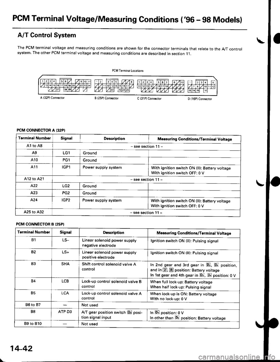
PCM Terminal Voltage/Measuring Gonditions ('96 - 9g Models)
A/T Control System
The PCM terminal voltage and measuring conditions are shown for the connector terminals that relate to the A"/T controlsystem. The other PCM terminal voltage and measuring conditions are described in section I l.
A l32P) Conn€ctotB I25P) ConnectorC (31P)ConngctorD (16P)Connector
PCM CONNECTOR A I32P}
Terminal NumborSignalDcacriptionMoasuring Conditions/Te.minal Voltage
A1 to A8- see section 1 I -
A9LG1Ground
A10PG1Grou nd
A11IGPlPower supply systemWith ignition switch ON (ll): 8attery voltage
With ignition switch OFF: 0 V
412 to A2l- see section I I -
Ground
423PG2Ground
A'24IG P2Power supply systemWith ignition switch ON (ll): Battery voltage
With ignition switch OFF: 0 V
A25 to A32- see section l1 -
PCM CONNECTOR B (25P}
Terminal NumberSignalDescriptionMeasuring Conditions/T6rminal Voltage
B1LS-Linear solenoid power supply
negative electrode
lgnition switch ON (ll): Pulsing signa.
82Linear solenoid power supplypositive electrode
lgnition switch ON (ll): Pulsing signal
SHAShitt control solenoid valve A
controlIn 2nd gear and 3rd gear in E, E position,
and in @, @ position: Battery voltage
In lst gear and 4th gear in E. E position: 0 V
B4LCBLock-up control solenoid valve B
control
When full lock-up: Battery voltage
When half lock-up: Pulsing signal
B5LCALock-up control sol€noid valve AcontrolWhen lock-up is ON: Battery voltage
With no lock-up: 0 V
86 to 87Not used
B8ATP D3IVT g6ar position switch @ posi-
tion signal input
lnEposition; OV
In other than E position: Battery voltage
Bg to 810Not used
\-
14-42
Page 725 of 2189

FCM CONNECTOR D {16P)
\o
14-47
Terminal NumberSignalDo3criptionMeasuring Conditions/Torminal Vohage
D1LCALock-up control solenoid valve A
control
When lock-up is ON: Battery voltage
With no lock-up: 0 V
SHBShift control solenoid valve B
control
In E position, in 1st and 2nd gear in E, E
position: Battery voltage
ln 3rd gear in E, E, in 4th gear in E posi-
tion;0 V
D3LCBLock-up control solenoid valve B
control
When full lock-up: Battery voltage
With half lock-up: Pulsing signal
D4Not used
D5VB SOLLock-up control solenoids, shift
control solenoids and linear
solenoid power supply electrode
with ignition switch oN (ll): Battery voltage
With ignition switch OFF: 0 V
D6ATP RAy'T gear position switch
E position input
tnEposition:0V
In other than E position: Approx. 10 V
SHAShift control solenoid valve A
control
In E] position, in 2nd and 3rd gear in p!, [Q]
position: Battery voltage
In 1st gear in E, @ position, in 4th gear in El
Dosition: 0 V
D8ATP D3A/T gear position switch
E position input
In E position:0V
In otherthan @ position: Approx. 10 V
D9ATP D4Ay'T gear position switch
E position switch
In El position: 0 V
In other than E position: Approx. 5 V
D10NCCountershaft speed sensor signal
input
Depending on vehicle speed: Pulsing signal
When vehicle is stooped: 0 V
D11NMMainshaft speed sensor signal
Inpur
Depending on engine speed: Pulsing signal
When engine is stopped: 0 V
D't2NMSGMainshaft speed sensor ground
D13ATP NPAy'T gear position switch E and
E position input
InE and E positions: 0V
In other than E and E positions: Approx. 10 V
D14AfP 2Ay'T gear position switch
E position input
tnEposition;0V
In other than E position: Approx. 10 V
D16NCSGCountershaft speed sensor
ground