Page 1029 of 2189
![HONDA CIVIC 1998 6.G Workshop Manual l.
17.Make sure the transmission is in the E] position.
Fill the transmission with cvT Fluid, and run the
engine for 30 seconds or until approximately 0 95 {
(1.0 US qt.,0.8 lmp qt.) is discharged.
Re HONDA CIVIC 1998 6.G Workshop Manual l.
17.Make sure the transmission is in the E] position.
Fill the transmission with cvT Fluid, and run the
engine for 30 seconds or until approximately 0 95 {
(1.0 US qt.,0.8 lmp qt.) is discharged.
Re](/manual-img/13/6068/w960_6068-1028.png)
l.
17.Make sure the transmission is in the E] position.
Fill the transmission with cvT Fluid, and run the
engine for 30 seconds or until approximately 0 95 {
(1.0 US qt.,0.8 lmp qt.) is discharged.
Remove the drain hose, and reconnect the cooler
return hose to the transmission (see page 14-355)
Refill the transmission with CVT Fluid to the proper
level (see page 14-299).
18.
'19.
.l ,
TOOL MAINTENANCE
1. Empty and rinse after each use. Fill the can with water
and pressurize the can. Flush the discharge line to
ensure that the unit is clean.
2, lf discharge liquid does not foam, the orifice may be
blocked.
3. To clean, disconnect the plumbing from the tank at
the large couPling nut.
FILTER
\
\- 0--D
i
I
O.RING
Remove the in-line tilter from the discharge side and
clean if necessary'
The fluid orifice is located behind the filter. Clean it
with the pick stored in the bottom of the tank han-
dle. or blow it clean with air. Securely reassemble
all parts.
COUPLINGNUT
II
-@q
\ORIFICE
FILLER CAP
14-353
Page 1067 of 2189
It
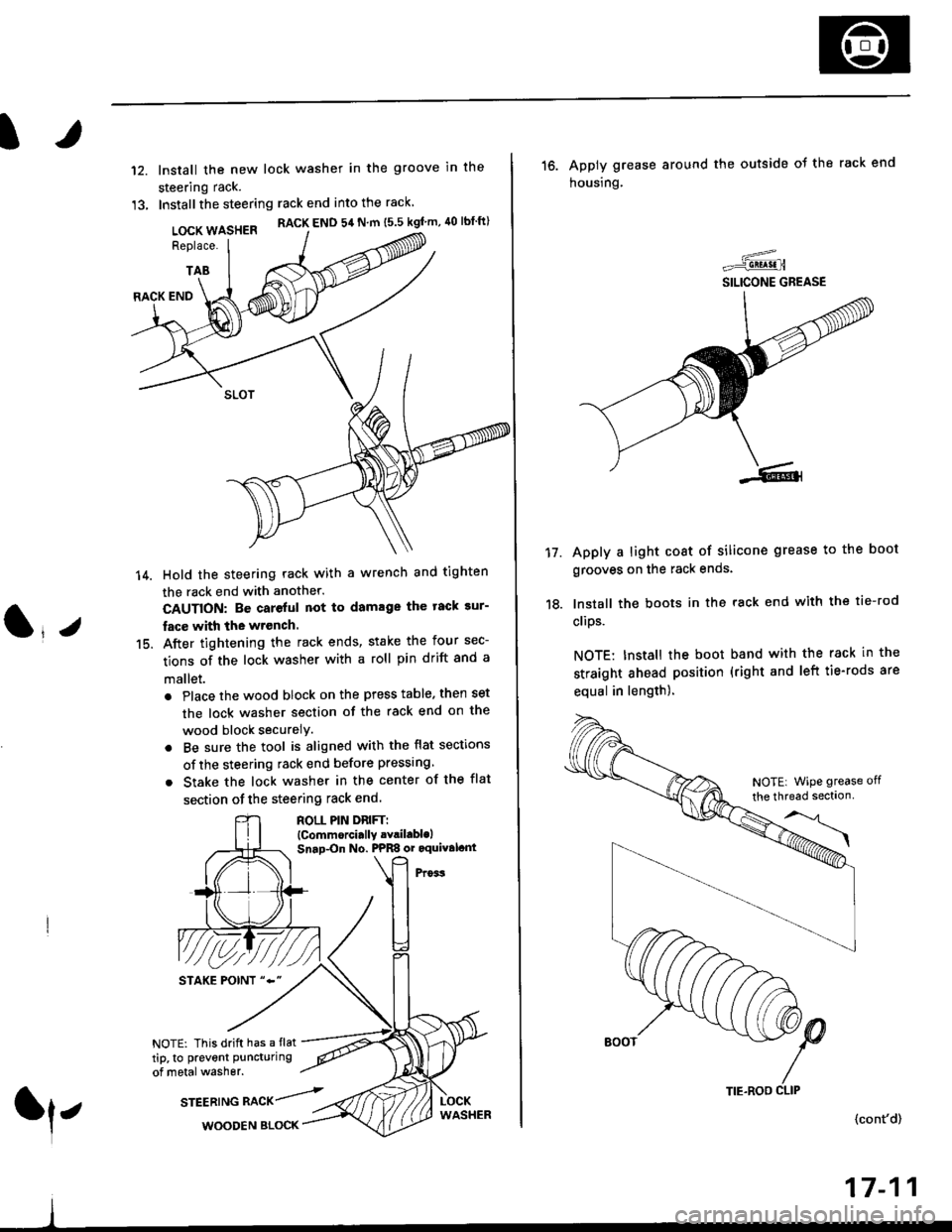
12.
13.
lnstall the new lock washer in the groove in the
steering rack.
Installthe steering rack end into the rack
LOCK WASHER RACK END 54 N m ts.s kgf'm, 40 lbtft)
Replace.
TAB
(l*v
14.
15.
RACK END
Hold the steering rack with a wrench and tighten
the rack end with another.
CAUTION: Be careful not to damage the tack sur-
fac€ with the wrench.
After tightening the rack ends, stake the four sec-
tions of the lock washer with a roll pin drift and a
mallet.
. Place the wood block on the press table. then set
the lock washer section of the rack end on the
wood block securelY.
. Be sure the tool is aligned with the flat sections
of the steering rack end before pressing
. Stake the lock washer in the center of the flat
section of the steering rack end.
ROLL PIN DnlFTl(Commorci.lly .Yril.blolSnap-On No. PPRS or oquival.nt
NOTE: This drift has a flat
tip, to prevent puncturing
of metal washer.
srEEatruG nlCr/rl,WOODEN BLOCK
TIE.ROO CLIP
16. Apply grease around the outside ot the rack end
housing.
Apply a light coat of silicone grease to the boot
grooves on the rack ends.
lnstall the boots in the rack end with the tie-rod
clips.
NOTE: Install the boot band with the rack in the
straight ahead position (right and left tie-rods are
equal in length).
=-..r=-q!q!!.n
SILICONE GREASE
17.
(cont'd)
17-11
NOTE| WiPe grease off
the thread sectlon
Page 1119 of 2189
)
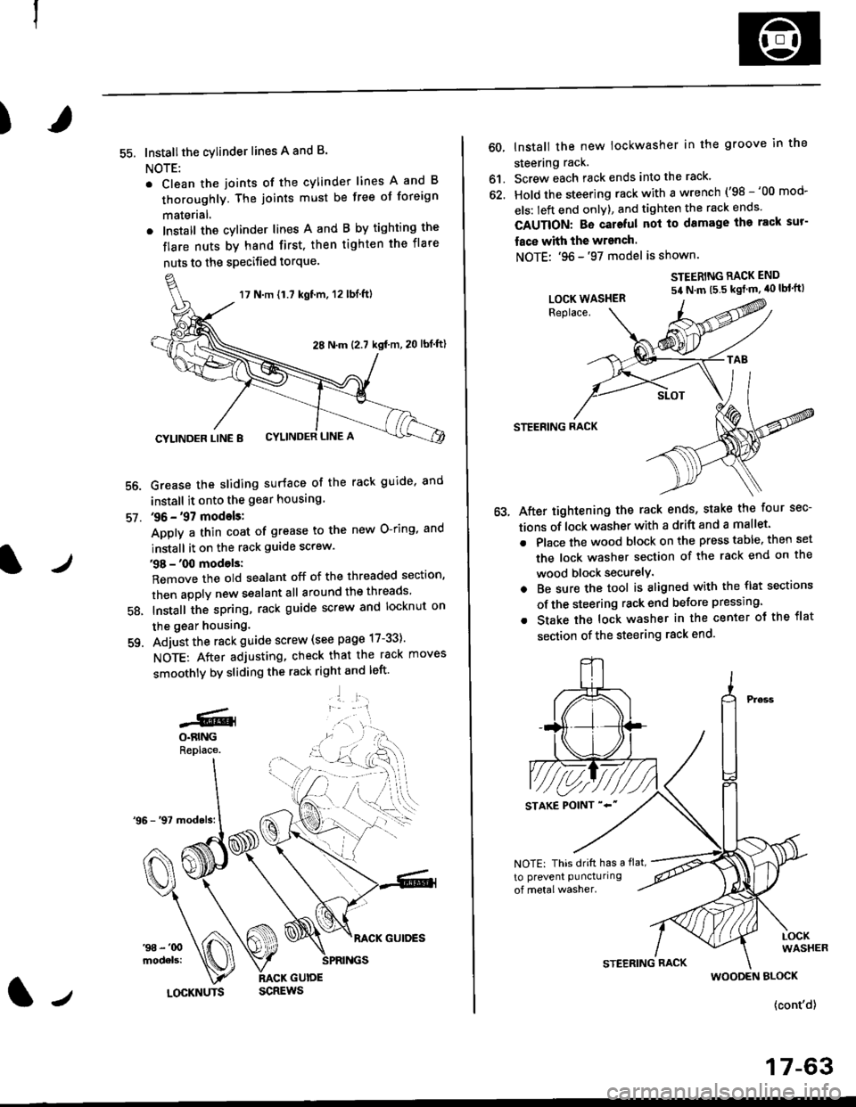
55. Installthe cylinder lines A and B.
NOTE:
. Clean the joints of the cylinder lines A and B
thoroughly. The joints must be free of foreign
materlal.
. Install the cylinder lines A and B by tighting the
flare nuts by hand first, then tighten the flare
nuts to the specified torque.
56.
57.
Grease the sliding surface of the rack guide, and
install it onto the gear housing
36 - '97 models:
Apply a thin coat of grease to the new O-ring, and
install it on the rack guide screw.
38 - '00 models:
Remove the old sealant off of the threaded section,
then apply new sealant all around the threads
Install the spring, rack guide screw and locknut on
the gear housing.
Adjust the rack guide screw (see page 17-33)'
NOTE: After adjusting, check that the rack moves
smoothly by sliding the rack right and left'
'1 l:.r1
58.
-GlO.BINGReplace.
17 N.m {1.7 kgt'm, 12 lbl.ft)
28 N.m (2.7 kgf m,20 lbf ftl
CYLINDER LINE 8 CYLINDER LINE A
l/LOCKNUTS
60, lnstall the new lockwasher in the groove in the
steering rack.
61. Screw each rack ends into the rack'
62. Hold the steering rack with a wrench ('98 -'00 mod-
els: left end onlY), and tighten the rack ends'
CAUTION: Bo cateful nol to damage ihe rack sur-
face with the wranch.
NOTE: '96 -'97 model is shown.
STEERING RACK END
54 N'm t5 5 kgt m' 40 lbl'ft)
STEERING RACK
After tightening the rack ends, stake the four sec-
tions of lock washer with a drift and a mallet.
Place the wood block on the press table. then set
the lock washer section of the rack end on the
wood block securelY.
Be sure the tool is aligned with the flst sections
of the steering rack end belore pressing.
Stake the lock washer in the center ot the flat
section of the steering rack end.
LOCK WASHER
NOTE: This drift has a flat,
to prevent puncturing
WOODEN BLOCK
{cont'd}
17-63
Page 1151 of 2189
IDisassembly/lnsPection
lr
Disassembly
1. Compress the damper spring with the spring com-
pressor according to the manufacturer's instruc-
tions, then remove the self-locking nut.
GAUTION: Do not compress the spring more than
necessary to remove the sell-locking nut.
STNUT SPRING COMPRESSOR:
lComm6rcially .vailablelERANICKo T/N MST-580A, T/N 7200, or equivalent
Release the pressure from the spring compressor.
then disassemble the damper as shown on page 18-
(|-r
lnspection
1. Reassemble all parts, except the sprlng.
2. Push on the damPer as shown.
WOODEN BLOCK
Check for smooth operation through a full stroke,
both compression and extension.
NOTE: The damper should move smoothly lf it
does not (no compression or no extension), the gas
is leaking, and the damper should be replaced.
Check Jor oil leaks, abnormal noises, and binding
during these tests.
{cont'd)
18-27
Page 1167 of 2189
Front Brake Caliper
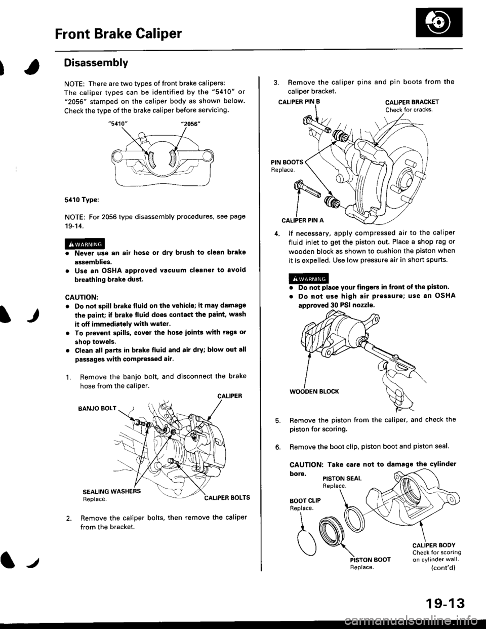
It
Disassembly
NOTE: There are two types of front brake calipers:
The caliper types can be identified by the "5410" or"2056" stamped on the caliper body as shown below.
Check the type of the brake caliper before servicing.
5410 Type:
NOTE: For 2056 type disassembly procedures, see page
19-14.
@o Never use an air hose ot dry brush to clean brakg
assemblies.
. Use an OSHA approved vacuum clganer to avoid
breathing brake dust.
CAUTION:
. Do not spill brake lluid on the vehicls; it may damage
the paint; if brake fluid does conlact the paint, wash
it off immedistely with waier.
. To prevenl spills, covet the hose ioin$ with rags or
shop towels.
. Clean all parts in brake fluid and air dry; blow out all
passages with compressed air.
L Remove the banjo bolt, and disconnect the brake
hose from the caliDer.
CALIPER
BANJO EOLT
SEALINGReplace.BOLTS
Remove the caliper bolts, then remove the caliper
from the bracket.
lJReplace.
3. Remove the caliper pins and pin boots from the
calioer bracket,
CALTPER PIN B CAL|PER BRACKET
CALIPER PIN A
4, lf necessary. apply compressed air to the caliper
fluid inlet to get the piston out. Place a shop rag or
wooden block as shown to cushion the piston when
it is expelled. Use low pressure air in short spurts.
@. Do not place your iingers in tront ol the piston.
. Do not use high air pressure; use 8n OSHA
approved 30 PSI nozzls,
Remove the piston from the caliper, and check the
piston for scoring.
Remove the boot clip, piston boot and piston seal.
CAUTION: Take care not to damage the cylindcr
PISTON SEALReplace.
BOOT CLIPReplace.
\,
,t. (
)PISTON BOOT
CALIPER BODYCheck for scoring
(cont'd)
19-13
Page 1168 of 2189
Front Brake Caliper
2056 Type:
@
Disassembly (cont'dl
Nevor u3e an air hos€ or dry brush to clgan brake
assomblios.
Use an OSHA approved vacuum cl6aner to avoid
braathing braks duet.
CAUTION:
. Do not spill brakefluid on ths vchicle; it may damage
the paint; if brako fluid does contact the p.int. wash
it olt immediately with wato..
. To prevsnt spills, cover the ho3o ioints whh rag3 or
shop towels.
. Cl€an all parts in brake fluid and air dry; blow out 8ll
passagss with compr63€d air.
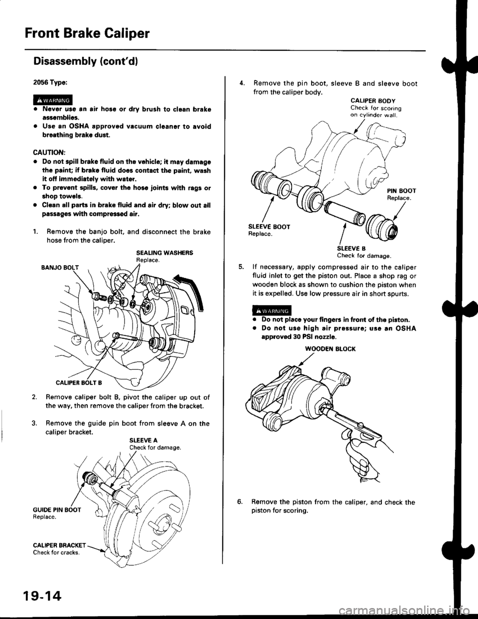
1. Remove the banjo bolt, and disconnect the brake
hose from the caliper.
SEALING WASHERS
Remove caliper bolt B, pivot the caliper up out of
the way, then remove the caliper from the bracket.
Remove the guide pin boot from sleeve A on the
caliDer bracket.
GUIDE PIN BOOTReplace.
GALIPER BRACKETCheck tor cracks.
Check for damage.
19-14
4. Remove the pin boot, sleeve B and sleeve boot
from the caliper body.
CALIPER EODYCheck for scoringon cytinder wa .
SLEEV€ BCheck for damage.
lf necessary, apply compressed air to the csliper
fluid inlet to get the piston out. Place a shop rag or
wooden block as shown to cushion the oiston when
it is expelled. Use low pressure air in short spurts,
a
a
Do not placo your lingers in ftont ol tho pkton.
Do noi usa high air prsssure; uso an OSHA
approved 30 PSI nozzle.
Remove the piston from the caliper, and check thepiston for scoring.
WOODEN ALOCK
Page 1178 of 2189
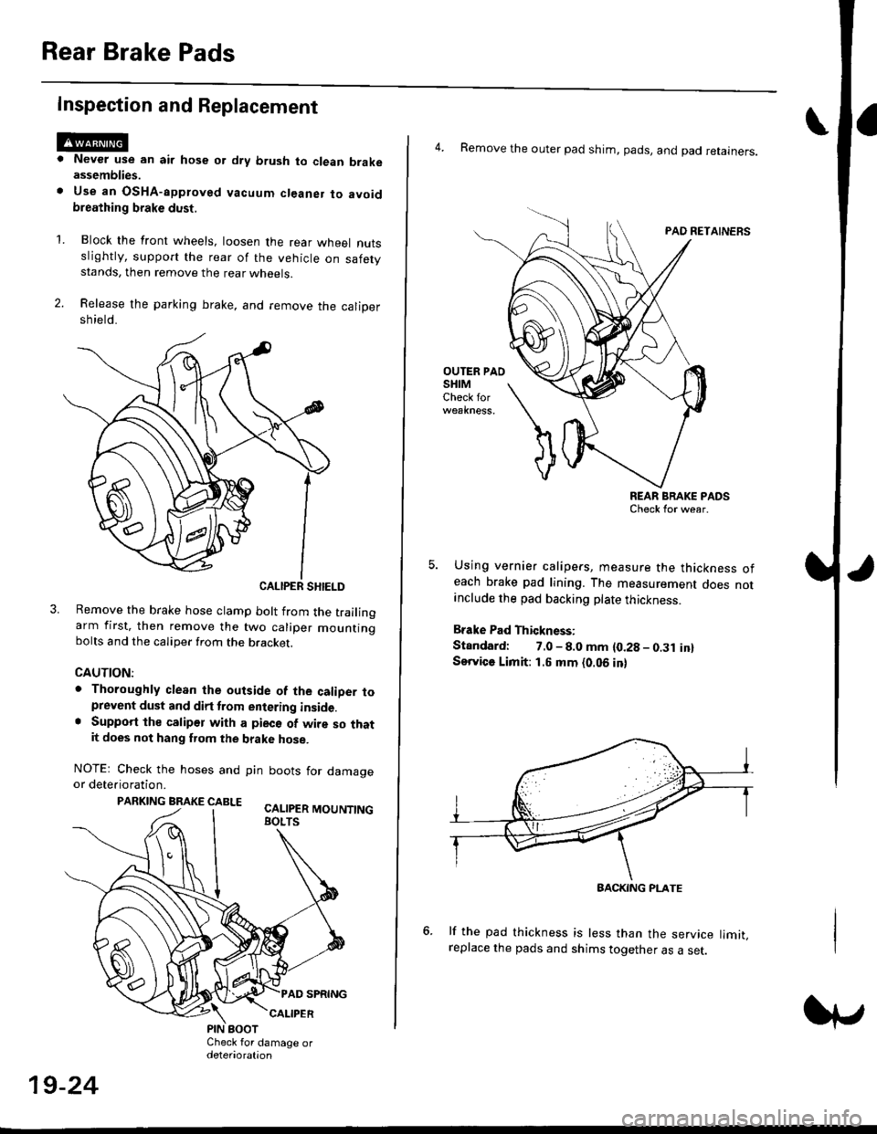
Rear Brake Pads
Inspection and Replacement
Never use an air hose or dry brush to clean brakeassemblies.
Use an OsHA-apptoved vacuum cl€aner to avoidbreathing brake dust,
Block the front wheels, loosen the rear wneet nutsslightly, support the rear of the vehicle on safetystands, then remove the rear wheels.
Release the parking brake, and remove the calioersh ield.
CALIPER SHIELD
Remove the brake hose clamp bolt from the trailingarm first, then remove the two caliper mountingbolts and the caliper from the bracket.
CAUTION:
. Thoroughly clean the outside of the caliDer toprevent dust and dirt trom entering inside.. Support the calipor with a pieco of wire so thatit does not hang fuom the brake hose.
NOTEr Check the hoses and pin boots for damageor deterioration.
PARKING BRAKE CABLE ^.. ._-_ ---.
'L
19-24
4. Remove the outer pad shim, pads, and pad retainers.
PAO RETAINERS
OUTER PAOSHIMCheck for
REAR BRAKE PADSCheck for wear.
Using vernier calipers, measure the thickness ofeach brake pad lining. The measurement does notanclude the pad backing plate thickness.
Brake Pad Thickness:
Standard: 7.0 - 8.0 mm {0.28 - 0.31 in}Service Limit: 1.5 mm {0.06 in}
lf the pad thickness is less than the service limit,replace the pads and shims together as a set.
BACKING PI-ATE
Page 1189 of 2189
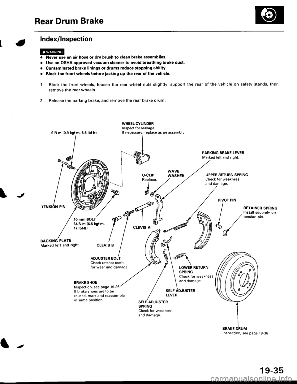
Rear Drum Brake
Index/lnspection
'1.
a
a
Never use an air hose or dly brush to clean brake assemblies,
Use an OSHA approved vacuum cleanar to avoid breathing brake dust,
Contaminated brake linings or drums reduce stopping ability.
Block the tront wheels before iacking up ths r€ar of lhe vehicle.
Block the front wheels, loosen the rear wheel nuts slightly, support the rear of the vehicle on safety stands, then
remove the rear wheels.
2. Release the parking brake, and remove the rear brake drum.
I N m 10.9 kgtm, 6.5 lbf.ftl
TENSION PIN
10 mm BOLT6,1N m 15.5 kgf m,47 tbf.ft)
WHEEL CYLINDERInspect for leakage.lf necessary, replace as an assembly.
u-cLrPReplace.
WAVEWASHER
PARKING BRAKE LEVERMarked left and right.
Check for weaknessano oamage,
UPPER RETURN SPRING
I
@JPIVOT PIN
BACKING PLATEMarked lelt and right-
/
€f-l.^
I I
*'t")
ctEv'sB
/ (t
/ ,.ro,".r r.*,"n
/ , Install securely on
| / tension pin.
d"/
IU
ADJUSTER BOI-TCheck ratchet teethfor wear and damage.LOWER RETURNSPRINGCheck for weaknessand oamage.BRAKE SHOEInspection, see page 19-36lf brake shoes are to bereused, mark and reassemblein same position.
SELF.ADJUSTERLEVEB
SELF-ADJUSTERSPRINGCheck for weaknessano oamage.
BRAKE DRUMInspection, see page '19 36
t
19-35