Page 96 of 2189

Engine RemovaUlnstallation
Removal
@@
1.
. Make sure iacks and salety stands are placed ploperly
and hoist brackets are attached to the correct posi-
tions on the engine.
. Make sure the vehicle will not roll off stands and fall
while you are working under it.
CAUTION:
. Use fender covers to avoid damaging painted sur-face.
. Unplug the wilin9 connectors caretully while holdingthe conngstor portion to avoid damage,. Mark all wiring and hosos to avoid misconnoction.
Also, be sure that they do not contact other wiring or
hoses or interfere with other parts,
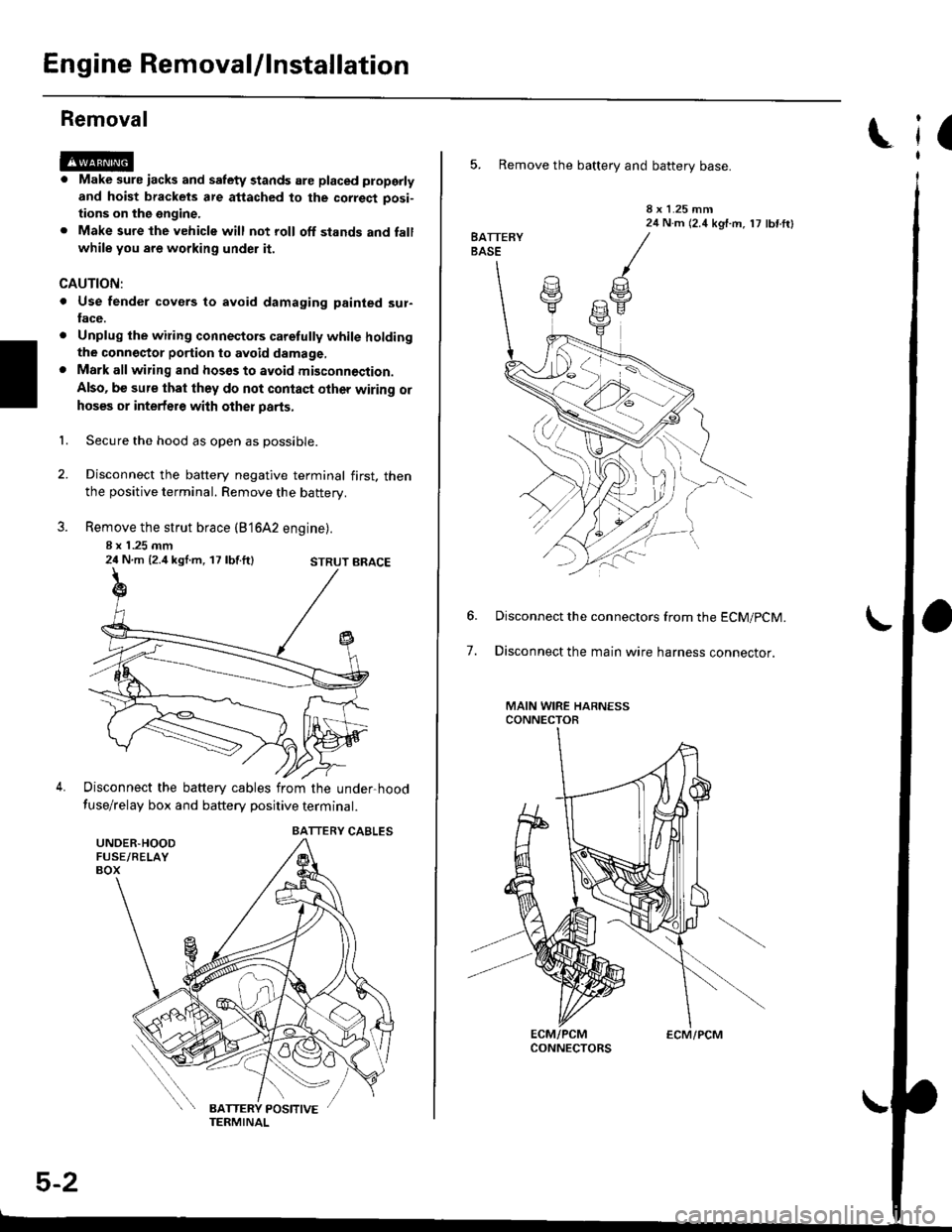
Secure the hood as open as possible.
Disconnect the battery negative terminal first. thenthe positive terminal. Remove the battery.
Remove the strut brace (B'16A2 engine).
8 x 1 .25 mm24 N.m {2.4 kgl.m, 17 lbf.ft}
Disconnect the battery cables from the under-hood
fuse/relay box and battery positive terminal.
STRUT BRACE
UNDER.HOODFUSE/RELAYBOX
BATTERY CABLES
5-2
ECM/PCM
(
5. Remove the battery and battery base.
8 x 1.25 mm24 N.m (2.4 kgf.m, 17 lbf ftl
7.
Disconnect the connectors from the ECM/pCM.
Disconnect the main wire harness connector.
MAIN WIRE HARNESSCONNECTOR
Page 138 of 2189

Removal
Engine removal is not required for this procedure
!!!s@ Make sure iacks and salety stands are
f ta"eata"ea propetty and hoist brackets are attached to the
correct positions on the engine.
CAUTION:
. Use tender covels to avoid damaging painted sul-
faces.
o To avoid damage, unplug the wiling connectors
carefully while holding the connector portion to
avoid damage.
. To avoid damaging the cylinder head, wait until the
engine coolant temperature drops below 100"F
{38"C} before loossning the tetaining bolts.
NOTE:
o Mark all wiring and hoses to avoid misconnectlon
Also, be sure that they do not contact other wiring or
hoses, or interfere with other parts.
. Inspect the timing belt before removing the cylinder
h ead.
. Turnthe crankshaft pu lley so that the No. lpistonisat
top dead center (see Page 6-21)
'1. Disconnect the negative terminal from the battery'
Drain the engine coolant (see page'10-7).
a Remove the radiator cap to speed draining.
Remove the intake air duct and air cleaner housing
(see page 5 3).
Remove the mounting bolt and lock bolt. then
remove the power steering (P/S) pump belt and
pump (see page 5'5).
Loosen the idler pulley center nut and adjusting
bolt' then remove the air conditioning (A'lc) com-
pressor belt (see Page 5-6).
Loosen the mounting nut and lock bolt. then
remove the alternator belt (see page 6-19).
Remove the P/S pump bracket (see page 5-12).
3.
4.
2.
6.
1.
8. Remove the throttle cable by loosening the locknut,
then slip the cable end out of the throttle linkage
NOTE:
. Take care not to bend the cable when removing it
Always replace any kinked cable with a new one
. Adjust the throttle cable when installing (see sec-
tion 1 1).
D16Y7 engine:
Dl6Y5, Dl6Y8 engines:
THFOTTLECABLE
(cont'd)
6-27
LOCKNUT
CABLE
Page 2060 of 2189

Security System (cont'd)
Security System Does Not Work ln Any
Mode (CX, DX)
1. ls luse 54 (in the under-hood fuse box) OK?
Yes - Go to the next step.
No - Repiace the blown fuse, then go to the
next step.
2. ls the fuse in the securiiy in-line fuse holder OK?
Yes - Go to the next step.
No - Replace the blown fuse, then go to next
srep.
3. Does either fuse blow again?
Yes - Locate and repair the short.
No - Retest the system.
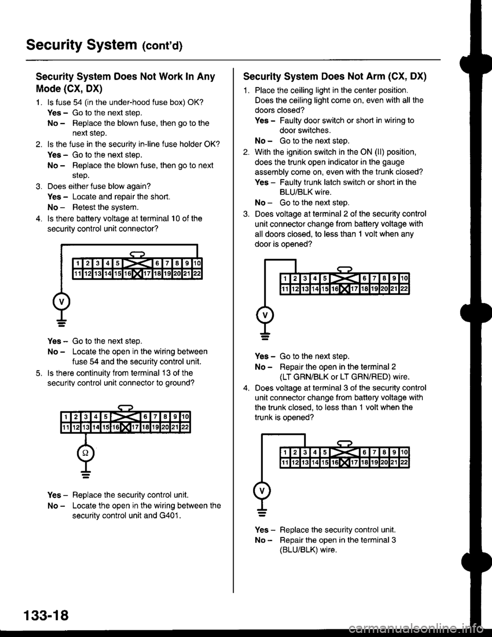
4. ls there battery voltage at terminal 10 of the
security control unit connector?
Yes - Go to the next step.
No - Locate the open in the wiring between
fuse 54 and the security control unit.
ls there continuity from terminal 13 ol the
security control unit connector to ground?
Yes - Replace the security control unit.
No - Locate the open in the wiring between the
securitv control unit and G401.
5.
133-18
Security System Does Not Arm (CX, DX)
1. Place the ceiling light in the center position.
Does the ceiling light come on, even with all the
doors closed?
Yes - Faulty door switch or short in wiring to
door switches.
No - Go to the next steo.
2. With the ignition switch in the ON (ll) position,
does the trunk open indicator in the gauge
assembly come on, even with the trunk closed?
Yes - Faulty trunk latch switch or short in the
BLU/BLK wire.
No - Go to the next step.
3. Does voltage at terminal 2 of the security control
unit connector change from battery voltage with
all doors closed, to less than 1 volt when any
door is ooened?
Yes - Go to the next step.
No - Repair the open in the terminal 2
(LT GRN/BLK or LT GRN/RED) wire.
Does voltage at terminal 3 of the security control
unit connector change from battery voltage with
the trunk closed, to less than 1 volt when the
trunk is oDened?
v]" - R"pt"." tne security control unit.
No - Bepair the open in the terminal 3
(BLU/BLK) wire.