Page 1299 of 2189
Glove box removal:
Remove the bolts, then remove the glove box.
>: Bolt locations,2
Installation is the reverse of the removal proceoure
Side air vent/Side defogger trim removal:
SIOE DEFOGGER TRIMSHOPTOWET_Carefully PrY rt at the
then remove it,side edge,
SIDE AIR VENTRemove the driver's dashboard lower
cover, or oPen the glove Dox,
HOOKS
then push the cliPs from each
opening by hand, and Pull it
out. Disconnect the connedors(driver's side).
HOOKS
DASH LIGHTSBRIGHTNESSCONTROLLERCONNECTOR{for some models)
CFUISE CONTROLMASTER SWITCHCONNECTOR(for some models)
Center dashboard lower covel:
1. Remove:
. Driver's dashboard lower cover
. Glove box
2. Remove the screws and bolt, then remove the cen-
ter dashboard lower cover. Disconnect the accesso-
ry socket connector'
>i Boh, screw locations
a>, 1 B>'5
A s*o.e-- I A
@;*;ry'-1'-.J _e)
3. Installation is the reverse of the removal proceoure'
(cont'd)
20-69
LOWER COVER
Page 1381 of 2189
Heater Control Panel Input/Output Signals
HEATER CONTROL PANEL lilP CONNECToR
Wire side of lemale terminals
21-7
Terminal
No.
Wire
colorSignalTerminal
No.
Wire
colorSignal
1YELHEAT/DEFINPUT8YEVREDVENTINPUT
BLfiELINPUT9G RNI/ELHEATIr'ENTINPUT
WHT/BLU+BINPUT'10BLKGROUNDOUTPUT
4YEUBLUDEFINPUT11*BLU/REDA./C THERMOSTATINPUT
5REDDASH LIGHTS
BRIGHTNESS CONTROLLEROUTPUT12GRN/WHTFRESHINPUT
6RE D/8LKCOMBINATION LIGHT
SWITCHINPUT13GRN/REDRECIRCULATEINPUT
1BLUMHTHEATINPUT14GRNHEATER FAN SWITCHOUTPUT
Page 1410 of 2189

Troubleshooting -'99 - 00 Models
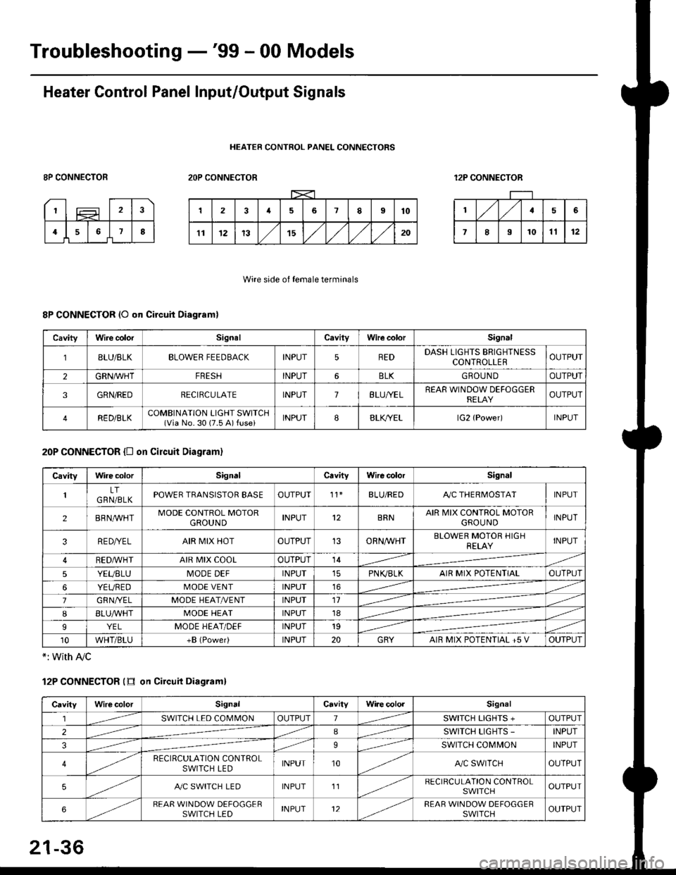
Heater Control Panel Input/Output Signals
HEATER CONTROL PANEL CONNECTORS
8P CONNECTOR2OP CONNECTOR12P CONNECTOR
Wire side of female terminals
8P CONNECTOR (O qn Circuit Diagram)
20P CONNECTOR {D on circuit Diagram}
*: with Ay'c
12P CONNECTOR (tr on Circuit Diagraml
CavityWire colorSignalCavilyWhe colorSignal
BLU/8LKBLOWER FEEDBACKINPUT5REDDASH LIGHTS BRIGHTNESSCONTROLLEROUTPUT
2GRN/lVHTFRESHINPUT6BLKGBOU N DOUTPUT
3GRN/REDRECIRCULATEINPUT7BLU/YELREAR WINDOW DEFOGGERRELAYOUTPUT
4RED/BLKCOMBINATION LIGHT SWITCH(Via No. 30 (7.5 A) fuse)INPUT88LfiELlG2 {Power)INPUT
CavityWire colorSignalCavityWire colorSignal
LTGRN/BLKPOWER TRANSISTOR EASEOUTPUT't1BLU/REDAy'C THERMOSTATINPUT
2BRNMHTMODE CONTROL MOTORGROUNDINPUT12BRNAIR MIX CONTROL MOTORGROU NDINPUT
3RE D/YELAIR MIX HOTOUTPUT13ORNAA/HTBLOWER MOTOR HIGHRELAYINPUT
RED,ryvHIAIR MIX COOLOUTPUT14
5YEUBLUMODE DEFINPUTPN K,/BLKAIR MIX POTENTIALOUTPUT
6YEUREDMODE VENTINPUT16
7GRNI/ELMODE HEAT/r'ENTINPUT11
IBLUAVHTMODE HEATINPUT18
9YELMODE HEAT/DEFINPUT19
10WHT/BLU+B (Power)INPUT20GRYAIR MIX POTENTIAL +5 VOUTPUT
CavityWilecolorSignalCavityWi.e cololSignal
lSWITCH LED COMMONOUTPUT1SWITCH LIGHTS +OUTPUT
2ISWITCH LIGHTS -INPUT
39SWITCH COMMONINPUT
4RECIRCULATION CONTROLSWITCH LEDINPUT10A,/C SWITCHOUTPUT
5A./C SWITCH LEDINPUT11RECIRCULATION CONTROLSWITCHOUTPUT
6REAR WINDOW DEFOGGERSWITCH LEDINPUT12REAR WINDOW DEFOGGEBSWITCHOUTPUT
21-36
Page 1471 of 2189

l'f .
Electrical
Special Toofs .,....................,23-2
Troubleshooting
Tips and Precautions ..............,.................... . 23-3
Five-step Troubleshooting .............. ......... . . 23-5
wire color codes ..........,23-5
Schematic Symbols ........,................... . . .. .... 23-6
Relay and Control Unit Locations
Engine Compartment ...,..................... ... .. . 23'7
Dashboard ......................23-8
Dashboard/Door ......... 23-12*Airbags ................. ....... Section 24
Air Conditioning ......... Section 21
Aftelnator ..........."""" """ 23-112
Anti-lock Brake System {ABS) Section 19*A/T Gear Position Indicator .....................,. .... ... 23-149
Automatic Transmission Svstem .... . ....... Section 14
Batterv ......... . . . ... ...... .......23-91
Blower controls .. . ... Section 2l
Charging System ....'...........23'112
Connector ldentilication and Wire Harness
Routing .................. ......23'13
Cruise Control ............,........23-240
Dash Lights Brightness Controller ............. ....... 23-180
Fan controfs "" 23'126
Fuel PumD ........ . ........ section 11
Fuses/Refay ...............,..,,.. 23'62
PGM-FI Control System ......................,....... Section 1 1
*Gauges
Circuit Diagram ....,.,.......23-131
Fuef Gauge ...........'.'.......23-142
Gauge/lndicator .. . .. 23-129
Ground Distribution .. . 23-75
Heatei controls .. . ..... Section 21*Horn................. ...............23-196
*tgnition Switch ....................23-89
lgnition System .......,.... 23-102
*lntegrated Control Unit ....................................... 23-156
fnterlock System ,........ . . , ,23-144
Lighting System . . . .. ......... 23-161
Lights, Exterior
Back-up Lights ..'............23'171
Brake Lights .................. 23'174
Daytime Bunning Lights (Canadal ............... 23'166
Front Parking Lights ......,................ .'. .......... 23-167
Front Turn Signal Lights .......... . . ............ ..,.23-167
Headtights ....".'....-... ..... 23'167
High Mount Brake Light ...................... ... .23'179
License Plate Lights ...... 23'176
Taitfights ................ .......23'171
lnterior Lights ..-.......,, . 23-142
Moonroof ..,.................,........ 23-235
Power Distribution ....... . . .23-61
Power Door Locks .......,,,. .23'251
Power Mirrors ,..............,.,...23'206
Power Relays ....... . ...... . . .. 23-86
Power Windows ............,,....23-220
Rear Window Defogger .......................... . . ... . . 23-2OO
Spark Plugs . ..... . ........ .....23-111
Slarting System ................23-93*stereo Sound Svstem ,................. ..... ... . ... ,.,.,,23'147'Supplemental Restraint System (SRS) ... . Section 24
Turn Signal/Hazard Flasher System .......'.'....-... 23-173
*Undel-dash Fuse/Relay Box ............,.................. 23-85
vehicfe soeed sensor (VSSI """" ""' 23-140+Wipers/Washers .........,.,.,...23-214
NOTE: Unless otherwise specified, references to auto-
matic transmission (Mf) in this section include the CVT.
Page 1478 of 2189
Relay and Control Unit Locations
Dashboard: '96 - 97 models
CRUISE CONINOL UNIT
DAYTIMERUNNING LIG}ITSCONTROL UNITlCan!dal
IWire colo.s: GRN/ORN, GRN/RED,l
IWHT, YEL, and BLK I. MOONROOF CLOSE RELAYfwir. colorc: GRN/ORru, Cnru/VeLl
IWHT. GRN/RED, and ALK I
DASH LIGHTS BRIGHTNESS CONTROLLER{Has built-in control unit)
23-8
Page 1480 of 2189
Relay and Control Unit Locations
Dashboard: '98 - 00 models
CRUISE CONTROL UNIT
DAYTIMERUNNING LIGIfiSCONTROL UNITlCrnrda)
DASH LIGHTS BRIGHTNESS CONTROLLER{Has built-in control unit}
STARTEB CUI RELAY
[wi]e color.: BLX/WHT, exnfxf, IIBLU/BLK, |nd BLK/RED j
coloE: WHT/GRN, BLU/REO,IandWHT/GRN I
MOONROOF CLOSE RELAY
fwiro colors: GRN/O8ru. CnrulYel,l
IWHT, GBN/RED, end BLK I
23-10
Page 1509 of 2189

D
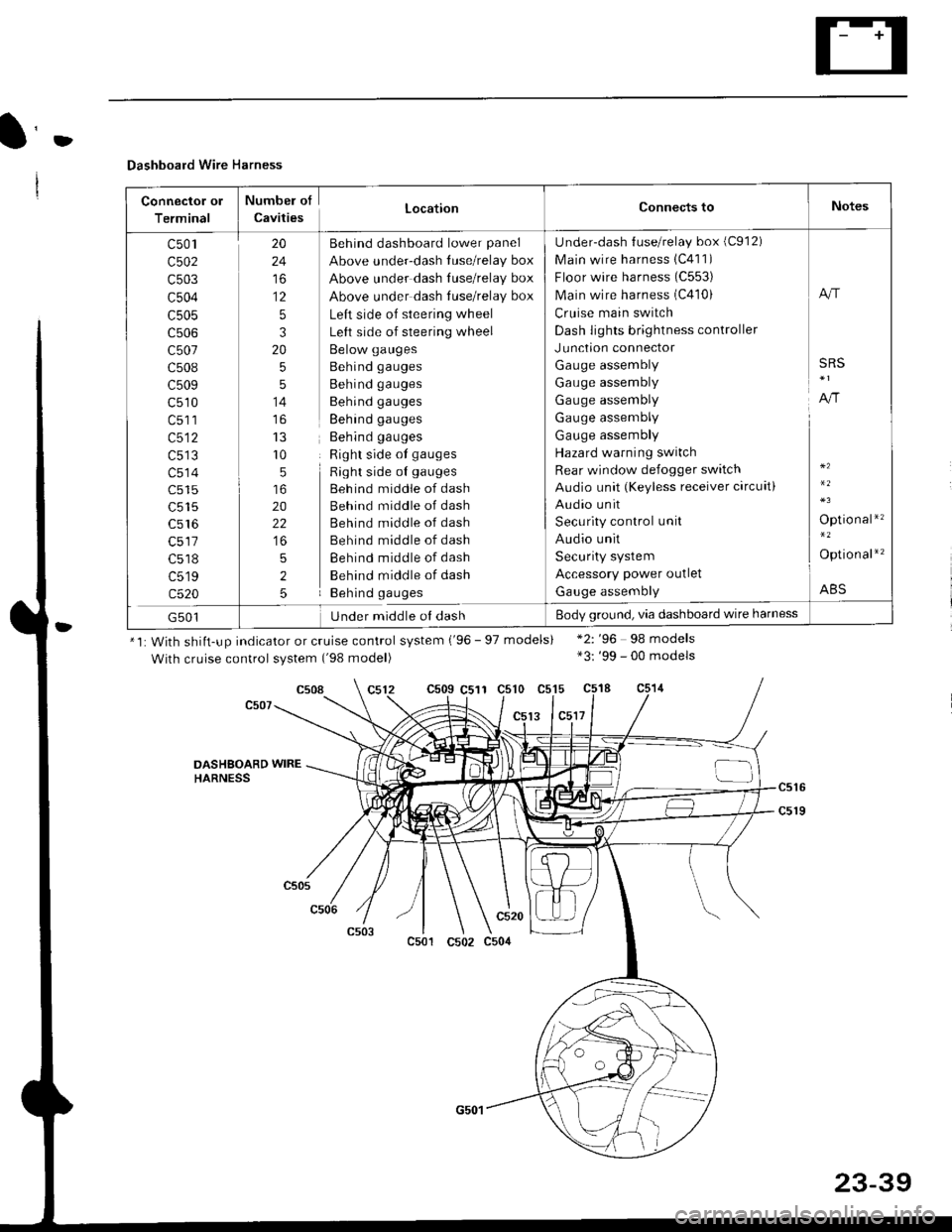
Dashboard Wire Harness
Connector ol
Terminal
Numbel of
CavitiesLocationConnects toNotes
c501
c502
c503
c504
c505
c507
c508
c509
c510
c513
c514
c515
c516
c518
c519
c520
20
24
to
12
5
3
20
5
5
14
r0
5
20
22
5
2
5
Behind dashboard lower panel
Above under-dash luse/relay box
Above under dash Iuse/relay box
Above under dash tuse/relay box
Left side of steering wheel
Left side of steering wheel
Below gauges
Behind gauges
Behind gauges
Behind gauges
Behind gauges
Behind gauges
Right side ot gauges
Right side oI gauges
Beh ind middle of dash
Behind middle of dash
Behind middle of dash
Behind middle of dash
Behind middle of dash
Behind middle of dash
Behind gauges
Under-dash {use/relay box (C912)
Main wire harness 1C411)
Floor wire harness (C553)
Main wire harness (C410)
Cruise main switch
Dash lights brightness controller
Junction connector
Gauge assembly
Gauge assembly
Gauge assembly
Gauge assembly
Gauge assembly
Hazard warning switch
Rear window defogger switch
Audio unit (Keyless receiver circuit)
Audio unit
Security control unit
Audio unit
Security system
Accessory power outlet
Gauge assembly
A"r
SRS
A,/r
Optio nal*'�
Option al*'�
ABS
G501Under middle ol dashBody ground, via dashboard wire harness
*1: With shiit-up indicator or cruise control system ('96 - 97 models)
With cruise control system ('98 model)
c509 C511 c510 c515
13 lc5l7
*2: '96 98 models*3: '99 - 00 models
c508
DASHSOARD WIREHARNESS
c501
c520
c502 c504
23-39
Page 1623 of 2189

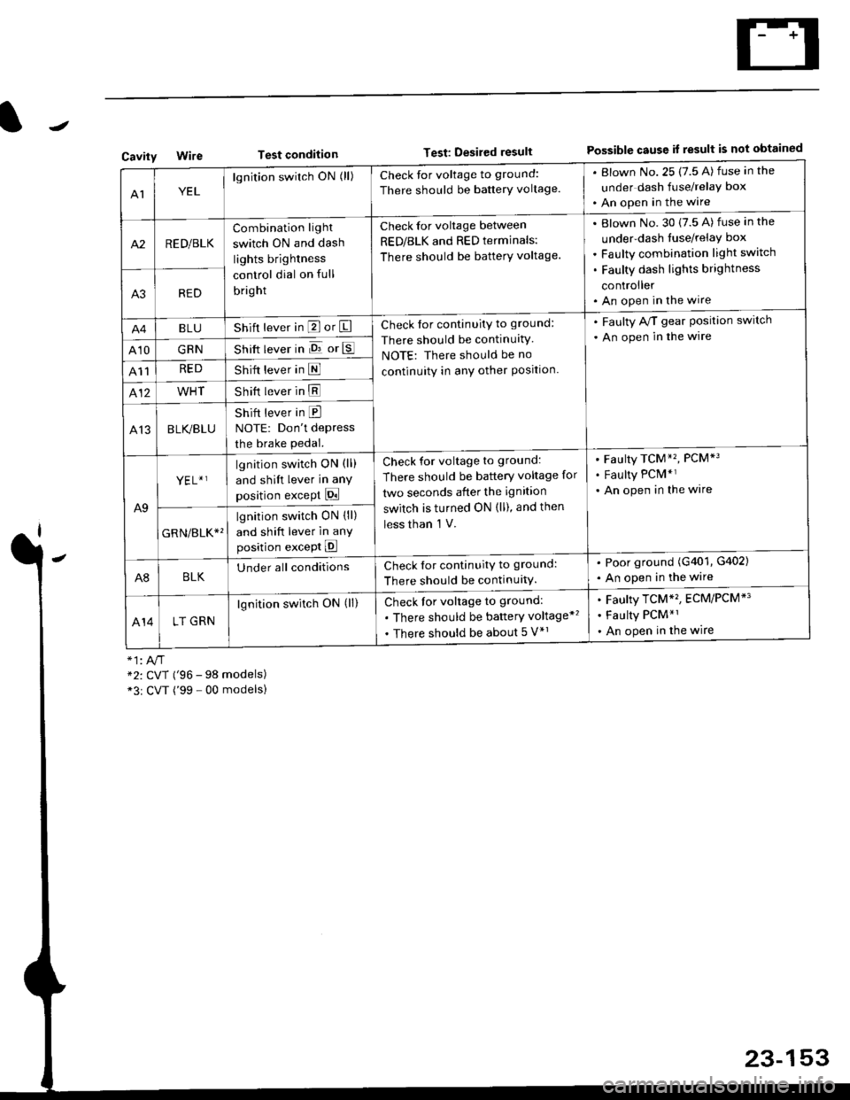
Test conditionTest: Desired resultPossible cause it result is not obtainedCavity
AIYEL
lgnition switch ON (ll)Check for voltage to ground:
There should be banerY voltage.
. Blown No.25 (7.5 A) fuse in the
under dash fuse/relay box
. An open in the wire
A2RED/BLK
Combination light
switch ON and dash
lights brightness
control dial on full
bright
Check for voltage between
RED/BLK and RED terminals:
There should be batterY voltage.
Blown No. 30 {7.5 A) fuse in the
under-dash tuse/relay box
Faulty combination light switch
Faulty dash lights brightness
controller
An open in the wireA3RED
BLUShift lever in P or ICheck for continuity to ground:
There should be continuitY
NOTE: There should be no
continuity in anY other Position.
. Faulty A/T gear Position switch
. An open in the wire
A10GRNShift lever in E or E
A11REDShift lever in E
412WHTShift lever in E
A13BLK/BLU
Shift lever in E
NOTE: Don't depress
the brake pedal.
A9
YEL+ ]lgnition switch ON (ll)
and shift lever in any
position except Pi
Check for voltage to ground:
There should be battery voltage for
two seconds after the ignition
switch is turned ON (ll), and then
less than 'l V.
Faulty TCM*'�, PCM*3
Faulty PCM*r
An open in the wire
GRN/err*'
lgnition switch ON {ll)
and shift lever in anY
position except E
A8BLKUnder all conditionsCheck for continuitv to ground:
There should be continuitY.
. Poor ground (G401, G402)
. An open in the wire
414LT GRN
lgnition switch ON (ll)Check for voltage to ground:
. There should be baftery voltage*'�
. There should be about 5 V*r
Faulty TCM*'�, ECM/PCM*'
Faulty PCM*1
An open in the wire
*2: CVT ('96 - 98 models)*3r CVT ('99 - 00 modelsl
23-153