1998 HONDA CIVIC low idle
[x] Cancel search: low idlePage 521 of 2189

Emission Gontrol System
System Description
The emission control system includes a Three Way Cata-lytic Convener (TWC), Exhaust Gas Recirculation (EGR)
system,. Positive Crankcase Ventilation (pCV) system andEvaporative Emission (EVAP) Control system. The emis-sion control system is designed to meet federal and stateemission standards.*: D16Y5 engine
Tailpipe Emission
Inspestion
@@ Do not smoke during ihis procedure. Keepany open flame away from your work area.
1. Start the engine. Hold the engine at 3,000 rpm withno load (in Park or neutral) until the radiator fancomes on. then let it idle.
2. Connect a tachometer.
Check and, if necessary, adjust the idle speed (see
page 11-220 - 223).
Warm up and calibrate the CO meter according to themeter manufacturer's instructions.
Check idle CO with the headlights, heater blower,rear window defogger, cooling fan, and air condition-er off.
NOTE: (Canada) Pull the parking brake lever up.Start the engine, then check that the headlights areoff.
CO mete. should indicate 0.1% maximum.
NOTE: '98 Dl6Y5 engine - lf the idle speed incress-es to 8101 50 rpm, this means the EVAp system ispurging the canister. To stop the purging temporari-ly. raise the engine speed above 1,000 rpm with theaccelerator pedal, then slowly release the pedal.
11-252
eFORWARD -
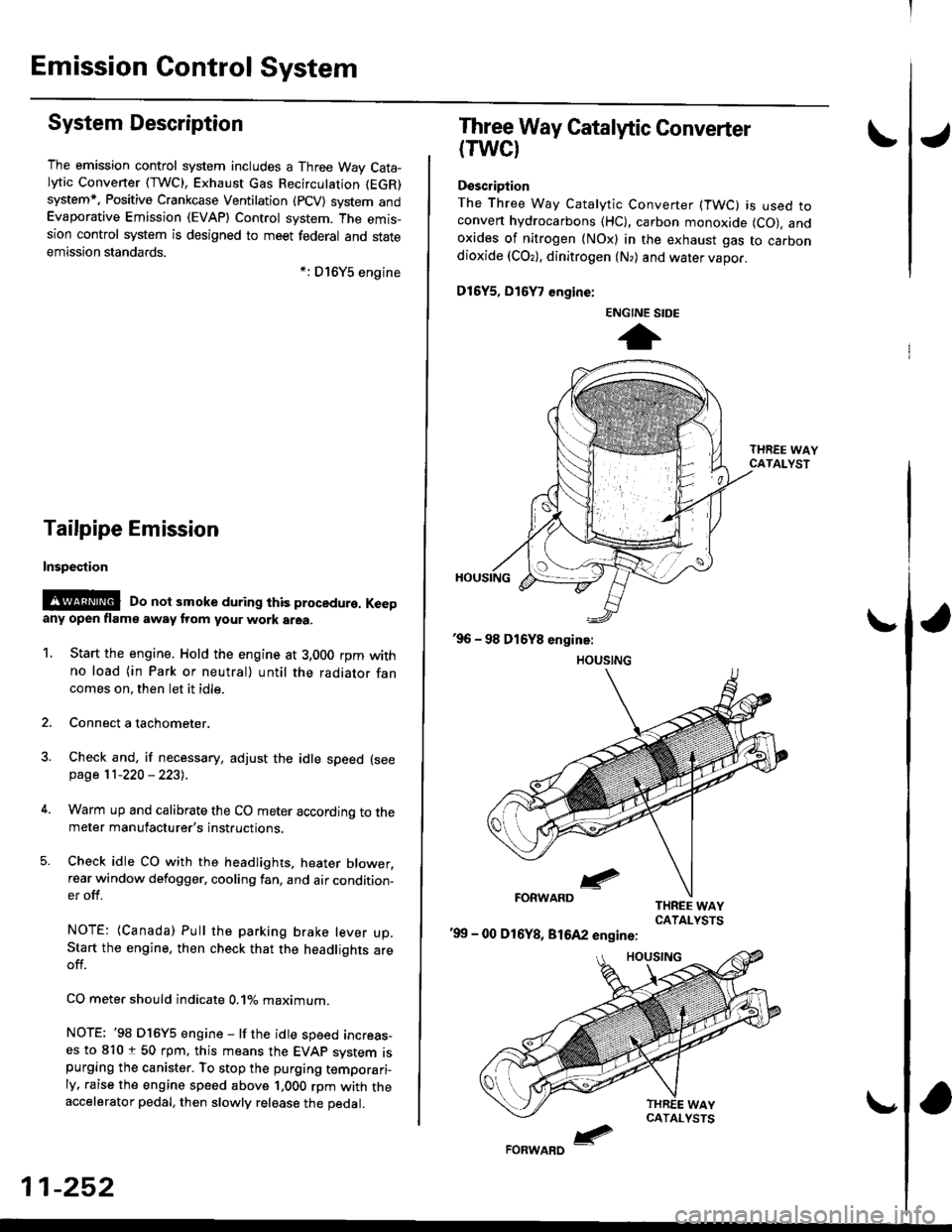
Three Way Catalytic Converter
(TWCI
Doscription
The Three Way Catalytic Converter (TWC) is used toconven hydrocarbons (HC), carbon monoxide (CO), andoxides of nitrogen (NOx) in the exhaust gas to carbondioxide (COr), dinitrogen (N,) and water vapor.
D15Y5, D16
, engine:
'99 - 00 D16Y8, 81642 engine:
ENGINE SIDE
t
Page 535 of 2189

Emission Control System
Positive Crankcase Ventilation IPCVI System
Descripiion
The Positive Crankcase Ventilation (PCV) system is
designed to prevent blow-by gas from escaping to the
atmosphere. The PCV valve contains a spring-loaded
plunger. When the engine starts, the plunger in the PCV
valve is lifted in proportion to intake manifold vacuum
and the blow-by gas is drawn directly into the intake
manifold.
D15Y5, D16Y8, 816A2 ongins:
BREATHERHOSE
Dl6'|11 6ngin6:
-: aLOW-BY VAPOR-: FnESH AIF
11-266
tJ
lrcpection
1. Check the PCV hoses and connections for leaks and
clogging.
2. At idle, make sure there is a clicking sound from the
PCV valve when the hose between the PCV valve
and the intake manifold is lightly pinched with your
fingers or pliers,
D16Y5, D16Y8 ongins:
BREATHERHOSE
PCV VALVE
Gently pinch here.
Bl6A2 engins:VALVE
lf there is no clicking sound, check the PCV valve
grommet for cracks and damage. If the grommet is
OK, replace the PCV valve and recheck.
PCV
Page 553 of 2189

Emission Control System
Evaporative Emission (EVAPI Controls (cont'dl
1
EVAP CONTROLCANISTER VENT SHUTVALVE 2P CONNECTOR IC141}
lltrt+ rcl
o) (8LK/YErl
I
temale terminalsWire side ot
ECM/PCM CONNECTOR A (32PI
VSV ILT GRN/WHT}
'l'
Wiro side of lemaletgrminals
VACUUMPUMP/GAUGE,0 - 30 in.Hg4973X -
041 - XXXXX
(From page 1l-283)
{To page 1l-285}
Check the vacuum whon cold:1. Disconnect the vacuum hoseshown from the EVAP controlcanrster and connect a vacuumgauge to the hose,2. Start the engine and allow itto idle.NOTE: Engine coolant tem-perature must be below 154oF(68'C) or lVC switch OFF.3. Ouickly raise the engine speedto 3,000 rpm.
(From page l1-283)
Check for an open in tho wire(lGl line):1. Turn the ignition switch OFF.2. Disconnect the 2P connectorlrom the EVAP control canis-ter vent shut valve.3. Turn the ignition switch ON (ll).4. Measure voltage between theEVAP controlcanister vent shutvalve 2P connector terminalNo. 2 and body ground.
Repair open in the wire betwe€nthe EVAP control c.ni3tei ventshut valve and th6 No. 15 ALTER-NATOR SP SENSOR 17.5 Al fuse.
Cfisck tor an opon in the wire (VSVline):1. Turn the ignition switch OFF.2. Beconnect the 2P connectorto the EVAP control canistervent shut valve.3. Turn the ignition switch ON (ll).4. Measure voltage betweenECM/PCM connector termi-nals A29 and Al0.
Rep.ir open in the wire betwoonthe EVAP control canister ventshut valve and th€ ECM/PCMtA29t.
ls there battery voltage?
Replace th6 EVAP control canis-ter vent 3hut valve.
PGT (BLKI
:lI23l'ltl'l lelsl ro Ir I1213t6€lnltlr@/lzzl zs f il
25
11-284
Page 558 of 2189

\
EVAP CONTROLCANISTER VENT SHUTVALVE 2P CONNECTOR IC141I
Wire side of temale terminals
ECM,/PCM CONNECTORS
tG1IBLK/WHT}
A973X -
0/r1 - XXXXX
Wire side of femaletermrnats
\
?,T-t
fl
VACUUMPUMP/GAUGE, 0 -30 in.Hg
\(cont'd)
11-289
{From page l1 288}
{To page 11-290)
Ch€ck the vac[um when cold:1, Disconnect the vacuum hoseshown from the EVAP controlcanister and connect a vacuumgauge to the hose.2. Start the engine and allow it
to idle.NOTEi Engine coolant temperature must be below 154"F(68'C) or Ay'C switch OFF.3. Ouickly raise the engine speedto 3,000 rpm.
(From page 11-288)
Check for an open in tha wire(lGt linol:1. Turn the ignition switch OFF.2. Disconnect the 2P connectorfrom the EVAP control canis-ter vent shut valve.3. Turn the ignition switch ON lll).4. Measure voltage between theEVAP control canister vent shut
valve 2P connector terminalNo.2 and bodyground.
Repair open in the wire betweenthe EVAP control canister ventshut valve .nd the No. 15 ALTER-NATOR SP SENSOR {7.5 A)fu3e.
ls there battery voltage?
Ch€d( for an op€n in the wiie IVSVlinel:1. Turn the ignition switch OFF.
2. R€connect the 2P connectorto the EVAP control canistervent shut valve,3. Turn the ignition switch ON (ll).
4. Measure vo ltage betweenECM/PCM connector termi-nals A4 and 82.
Repair open in the wire bctweenthe EVAP control canistor ventshut valve and lhe ECM/PCM{44t.
ls there battery voltage?
Rcolaco tho EVAP control canis.t6r vent shut valvo.
a t32P)
-
Page 690 of 2189

Description
Power Flow (cont'd)
El Po3ition
1, Hydraulic pressure is switched by the manual valve to the servo valve, which moves the reverse shift fork to thereverse position. The reverse shift fork engages with the reverse selector, reverse selector hub, and the countershaftreverse gear.
Hydraulic pressure is also applied to the 4th clutch. Power is transmitt€d from the mainshaft reverse gear via thereverse idler gear to the countershaft reverse gear.
The rotation direction of the countershaft reverse gear is changed via the reverse idler gear,
Power is transmitted to the final drive gear, which drives the final driven gear.
TOROUE
MAINSHAFT
COU TERSHAFT
REVERSE SELECTORHUBREVERSE SETICTOR
REVERSE SHIFTFORK
REVERSE IDLER
14-12
FINAL ON|VEN GEAR
Page 853 of 2189

Reverse ldler GearPark Stop
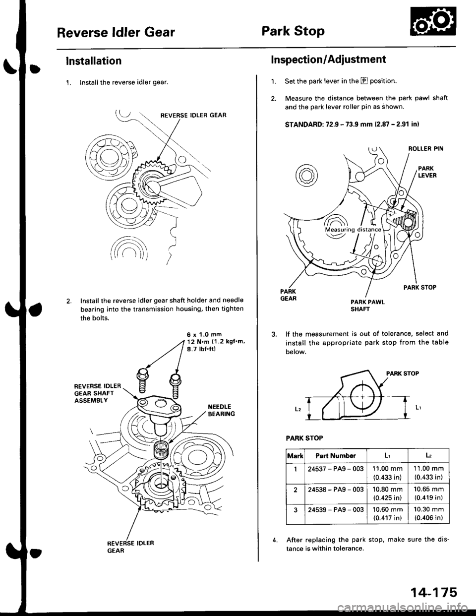
lnstallation
1, lnstall the reverse idler gear.
Install the reverse idler gear shaft holder and needle
bearing into the transmission housing, then tighten
the bolts.
6 x 1.0 mm12 N.m ll .2 kgf'm,
8.7 tbf.ftl
GEAR
'1.
Inspection/Adiustment
Set the park lever in the E position.
Measure the distance between the park pawl shaft
and the park lever roller pin as ahown.
STANDARD: 72.9 - 73.9 mm 12.87 - 2.91 inl
PARK PAWLSHAFT
lf the measurement is out of tolerance, select and
install the appropriate park stop from the table
Delow.
PARK STOP
PARK STOP
After replacing the park stop, make sure the dis-
tance is within tolerance.
/A\Measuring\v
MarkPart Numb€rLr12
I24537-PAg-00311.00 mm
(0.433 in)
11.00 mm
(0.433 in)
24538-PAg-00310.80 mm(0.425 in)
10.65 mm
(0.419 in)
24539-PAg-00310.60 mm(0.417 in)
10.30 mm(0.406 in)
14-175
Page 970 of 2189

Start Clutch Control@
T
Start Clutch Calibration Procedure
NOTE: When the following parts are replaced, the TCM
must memorize the feedback signal for the start clutch
control.
. TCM
. Transmissionassembly
. Stan clutch assembly
. Lower valve bodv assembly
. Engine assembly or overhaul
'96 Model Only
CAUTION: Do not uso this procsdure on'97 - (X) mod-
els or you will damage the transmission. On '97 - 00
models, the TCM or PCM memorizes ths loodback sig'
nals when you drive the vehicle.
1. Engage the parking brake, and block the front
wheels securely.
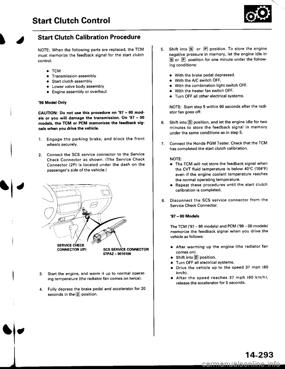
2. Connect the SCS service connector to the Service
Check Connector as shown. (The Service Check
connector (2P) is located under the dash on the
passenger's side of the vehicle.)
CONNECTOR07PAZ - lDl01(xt
Start the engine, and warm it up to normal operat-
ing temperature (the radiator fan comes on twice).
Fully depress the brake pedal and accelerator for 20
seconds in the E] position.
rl ,
CONNECTOR I2PI
14-293
7.
Shift into E o|. E position. To store the engine
negative pressure in memory. Iet the engine idle in
E or E position for one minute under the follow-
ing conditions:
. With the brake pedal depressed,
. with the y'\/c switch oFF.
. With the combination light switch OFF.
. With the heater fan switch OFF.
. Turn OFF all other electrical systems
NOTE: Start step 5 within 60 seconds after the radi-
ator fan goes off.
Shift into E position, and let the engine idle for two
minutes to store the feedback signal in memory
under the same conditions as in step 5.
Connect the Honda PGM Tester. Check that the TCM
has completed the start clutch calibration.
NOTE:
. The TCM will not store the feedback signal when
the CVT fluid temperature is below 40"C (104'F)
even if the engine coolant temperature reaches
the normal operating temperature.
. Repeat these procedures until the start clutch
calibration is completed-
Disconnect the SCS service connector from the
Service Check Connector.
'97 - 00 Models
The TCM ('97 - 98 models) and PCM ('99 - 00 models)
memorize the feedback signal when you drive the
vehicle as follows:
. After warming up the engine (the radiator fan
comes onl.
. Shift into E position.
. Turn OFF all electrical systems,
. Drive the vehicle up to the speed 37 mph (60
km/h).
. After the speed reaches 37 mph (60 km/h),
release the accelerator for 5 seconds.
Page 971 of 2189

Symptom-to-Component Chart
Hydraulic System
*1: Some gear noise is normal in the Lll position due to planetary gear action.
14-294
SYMPTOMCheck these items on the PBOBABLE CAUSE List
Engine runs, but vehicle does not move in any position.'t,2,3,4,5,6,7,8,9, 10, 20, 34, 35, 36, 38, 41
Vehicle does not move in @, [. p positions.10,11, 12, 20, 41
Vehicle does not move in E position.5, 'to, 11, 12, 17, 1A, 19, 20,39, 41
No shift to higher ratio,9, 13, 14. 15, 16,35,37,40
Poor acceleration.9, 13,'�t4,'t5,16. 20, 35, 37, 38, 40
Flares on moving.9,'t0, 20, 2't, 35, 36, 38, 40, 42
Excessive shock when depressing and releasing.^^alA/.r^r ^A.1. I9, 10, 20, 2'1, 35, 36, 3A, 42
No engine braking.9,20,21,35,36,38
Vehicle does not accelerate in lll position.9, 17, 18, 19, 20. 35, 36, 38
Vehicle moves in E position.
(Shift cable adjustment is proper).10, 22,23
Late shift from N position to E position, and from Eposition to E position.'10,11, 12,22, 41
Late shift from E position to E position. and from Eposition to N position.1l,'t2, 17, 18,22, 41
Engine stops when shifted to E position from E position.9, 10,20,35,37,34, 42
Engine stops when shifted to E position from I position.9, 18, 19,20,25,26,35,37,38, 42
Noise from transmission in @ position.rl5, 17, 18, 't9,25,26
Excessive idle vibration.2,3,4,21,24
Noise from transmission in @ and @ positions.2,3, 19,24,25,2A
Hunting engine speed.16, 35, 37, 38
Vibration in all position.8, 2a
Shift lever does not operate smoothly.11,29, 4'l
Transmission will not shift into lll position or transmis-
sion cannot be removed from E position.11 , 29, 30, 31, 32,33
Vehicle does not accelerate to more than a certain speed.9, 10, 14, 15,'t6,20,35,37
Excessive shock on starting off.38, 42
Flares on accelerating at low speed.20, 21 ,38, 42
Excessive vibration in E, E, tr, E positions.20,21,38, 42
Low engine speed in E. E. tr. E positions.20,21,38,42
Stall speed high.10,20,38
Stall speed low.9, 20, 27 ,37 , 38
Judder on starting off.20, 43