1998 HONDA CIVIC low idle
[x] Cancel search: low idlePage 391 of 2189

PGM-FI System
Manifold Absolute Pressure (MAPI Sensor
11-122
('99 - 00 Models except D16YS engine with M/T) (contd)
The scan tool indicates Diagnostic Trouble Code (DTC) P0108: A high voltage flow vacuum) problem in theManifold Absolute Pfessure (MAp) sensor,
MAP SENSOR 3P CONNECTOR (C111I
MAPIRED/GRNI
Wire side of female terminals
vcclIYEL/RED)
ECM/PCM CONNECTOR C (31PI
JUMPER WIRE
Wire side of female terminals
Tho MIL has boon rcDortod on.DTC ml 08 b stolod.
Problem verification:'1. Start the engine. Hold theengine at 3,000 rpm with noload (in Park or neutral) untilthe radiator fan comes on, thenlet it idle.2. Check the MAP with the scantoot,
Intormittent f.ilu.e, rystom is OXat thi! time. Chock tor poor con-n6ction3 or looso wirea at C111(MAP 3en.or) and tho ECM/PC-M.
ls 101 kPa (760 mmHg.30in.Hg) or higher indicated?
Check for an open in the MAPaon5('r:1. Turn the ignalion switch OFF.2. Disconnect the MAP sensor3P connector.3. Install a jumper wire betwesnthe MAP sensor 3P conn6ctorterminals No.3 and No.2.4. Turn the ignition switch ON {ll).5. Check the MAP with the scantool.
ls 101 kPa (760 mmHg, 30in.Hg) or higher indicated?
Check fo. an opcn in wiro (SGlline):1. Removo the jumper wire.2. Measure voltage between theMAP sonsor 3P connector terminals No. 1 and No.2.
Roprir opon in tha wiJo bctwoenthc ECM/FCM (C7l rnd the MApsonln t.
ls there approx. 5 V?
Chsck for an open in tho wi.e{MAP lino}:1. Turn the ignition switch OFF.2. Install a jumper wire on theECM/PCM connectors betweenC7 and C17.3. Turn the ignition switch ON (ll).4. Check the MAP with the scantool,
Repair op€n in the wir6a bstwoontho ECM/FCM (C171 and rh6 MApscnltoa.
ls 101 kPa (760 mmHg, 30in.Hg) or higher indicated?
Substituto a known-good ECM/PCM and rechcck, It normal MAPis indiceted. r.place tho originalECM/PCM.
JUMPER WIRE
--
Page 392 of 2189

L
Manifold Absolute Pressure (MAP) Sensor (cont'dl
The scan tool indicates Diagnostic Trouble code (DTc) P1128: Manifold Absolute Pressure (MAP) lower than
exoected.
The scan tool indicates Diagnostic Trouble code (DTC) P1129: Manifold Absolute Pressure {MAP) higher than
exoected,
- Tho MIL has been t€Ported on.- DTC P1128 is stored.
Problem verification:1. Turn the ignition switch ON (ll).
2. Check the MAP with the scan
tool.
lntermitteni failu.e, sYstom i! OK
at thb time.ls 54.1 kPa (406 mm Hg, 16.0
in. Hg) or higher indicated?
- The MIL has been roported on.- DTC P1129 is slorod
Problem v6rilicaiion:1. Start the engine. Hold the
engine at 3,000 rpm with no
load (in Park or neutral) until
the radiator fan comes on,
then let it idle.
2. Check the MAP with the scan
tool.
Int6rmittent failuto, sy3tem i3 OK
at thi3 time.ls 43.3 kPa (325 mm Hg, 12 8
in. Hg)or less indicated?
11-123
Page 397 of 2189
PGM-FI System
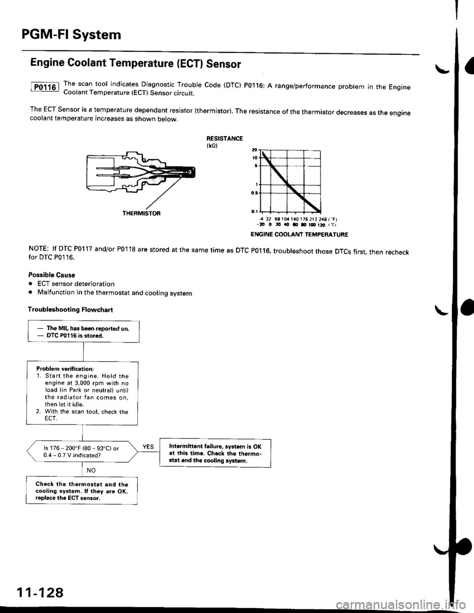
Engine Coolant Temperature (ECTI Sensor
The scan tool indicates Diagnostic Trouble code (DTC) P0116; A range/performance problem in the EngrneCoolant Temperature (ECT) Sensor circuit.
The ECT Sensor is a temperature dependant resistor (thermistor). The resistance of the thermistor decreases as the enginecoolant temperature increases as shown oetow.
RESISTANCE(ko)
NOTE: lf DTC P0117 and/or P01'18 are stored at the same time as DTCfor DTC P0116.
Possible Cause
. ECT sensor deterioration. Malfunction in the thermostat and cooling system
Troubleshooting Flowchart
-a 32 68 r0a la0l?6 2t2 2481'rr-20 o 20 ao o D r@ Il, r'c)
ENGINE COOLANT IEMPERATURE
P0116, troubleshoot those DTCS first. then recheck
11-128
THERMISTOR
- The MIL has bogn reported on.- DTC P0116 is stored.
Problem verification:1. Start the engine. Hotd theengine at 3,000 rpm with noload (in Park or neutral) untilthe radiator fan comes on,then let it idle.2. With the scan tool, check the
Intermiftent lailure. system is OKai thi. time. Ch.ck the thc.mo-stat 6nd thc cooling system.
is 176 200'F {80 - 93'C)or0.0-0.TVindicated?
Check the thermostat and thecooling system. ll they als OK,raplace the ECT sensor.
Page 438 of 2189
I
ll
t
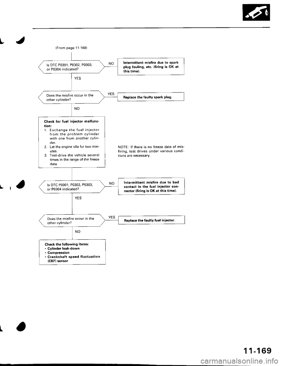
NOTE: lf there is no freeze data of mis_
firing, test drives under various condi
tions are necessary.
(From page 11'168)
Intermittent misfire due to sparkplug fouling, etc. (firing is OK arthis time).
ls DTC P0301, P0302, P0303,or P0304 indicated?
Does the misfire occur in theother cylinder?Replace the faulty spark plug.
Check for fuel iniector mallunc-
l|on:1. Exchange the fLrel injectorfrom the problem cylinderwith one from another cylinder.2. Let the engine idle for trrvo min-
utes.3. Test-drive the vehicle severaltimes in the range ot the freeze
data.
lntermitt€nt mistire due to badcontact in the fuel iniector con-nector (firing is OK at this time).
ls DTC P0301, P0302, P0303,or P0304 indicated?
Does the mistire occur in theother cylinder?Replace the taulty fuel injector.
Check lhe following items:. Cylinder leak-down. Compression. Crankshatt speod tluctuation
{CKF) sensoi
1 1-1 69
Page 447 of 2189

PGM-FI System
Barometric Pressure (BAROI Sensor
The scan tool indicates Diagnostic Trouble code (DTC) Pi106: A range/performance problem in the BaromerrrcPressure (BARO) Sensor circuit.
The scan tool indicates Diagnostic Trouble code (DTc) P1107: A low voltage probtem in the Baro sensor circurr.
The scan tool indicates Diagnostic Troubre code {DTC) p1108: A high vortage probrem in the Baro sensorcircuit.
fF1lot
tPlloal
The MIL ha3 been r€Dortsd on.DTC Pl106 is stored.
Problem verification:1. Do the ECM/PCM reset pro-cedure,2. Start the engine. Hold theengine at 3,000 rpm with noload (in Park or neutral) untilthe radiator fan comes on, thenlet it idle.3. Connect the SCS service connector.4. Test drive with the A/T in Eposition, M/T in 4th gear.5. Accelerate for five secondsusing wide open throttle.
Intormittont tailure, system is OKat this time.ls DTC P1106 indicated?
Substitut€ e known-good ECM/PCM and recheck. ll symptom/indication goes .way, .oplsce theo.iginal ECM/PCM.
The MIL has been .oported on.DTC P'l107 o. Pl108 is stored.
P.oblem veritication:1. Do the ECM/PClvl Reset pro
cedure,2. Turn the ignition switch ON (ll).
Intormittent frilure, syitem i3 OKat this time.ls DTC P1 107 or Pl108 indicated?
Substitute a known-good ECM/PCM and rechock. It symptom/indication goes away, .6placethe original ECM/PCM.
11-178
Page 450 of 2189
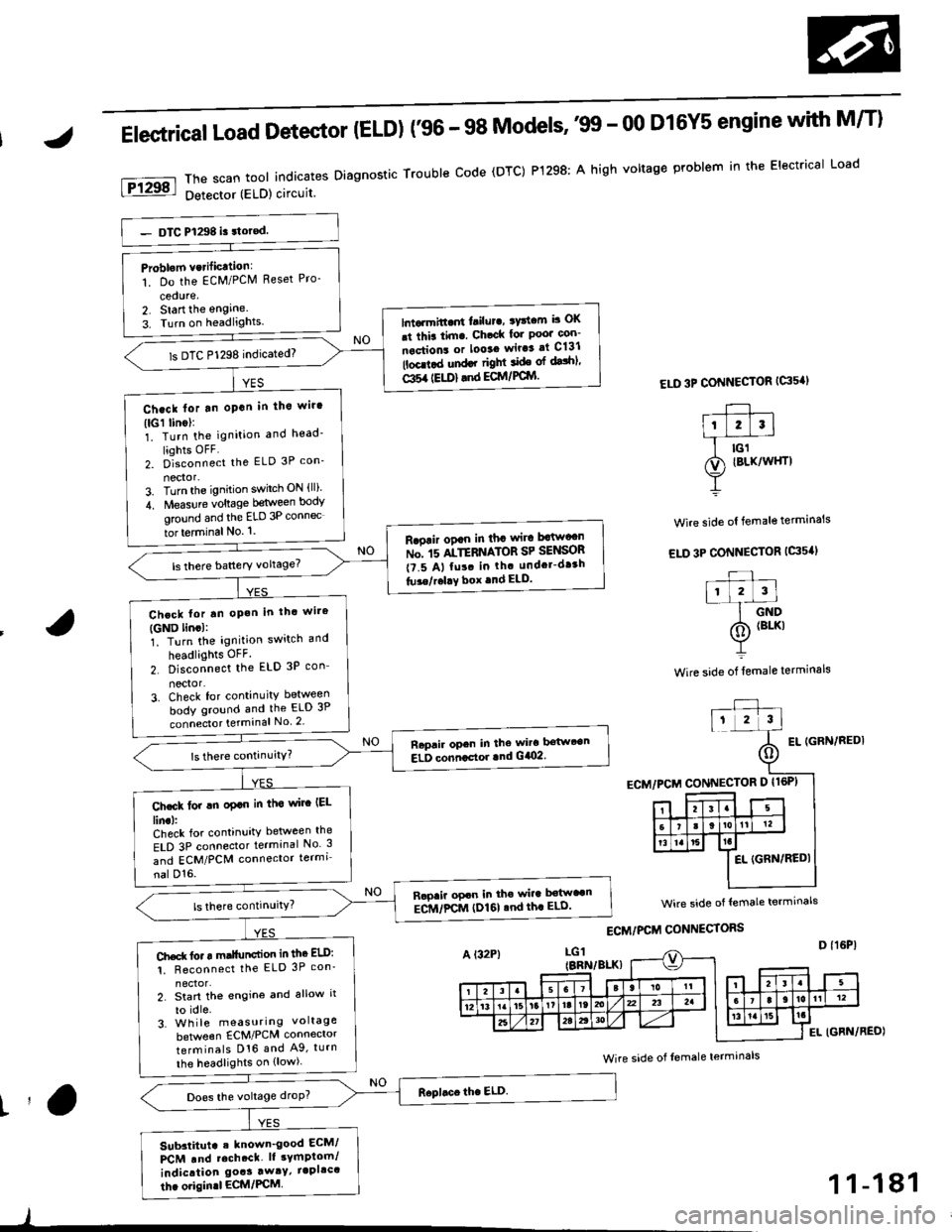
Elestrical Load Detector (ELD) f96 - 98 Models''99 - 00 D16Y5 engine with M/T)
ThescantoolindicatesDiagnosticTroubleCode(DTC)P1298:AhighvoltageproblemintheElectricalLoad
Detector (ELD) circuit
ELD 3P CONNECTOR {G's'I
Wire side ol female terminals
EL IGFN/REDI
Problom vcrificttion:
1. Do the EcM/PClVl Reset Pro-
cedure,2. Start the engine.
3. Turn on headlights.lntarmitt..rt l.ilur., ryttcm b OK
.t thia tim. Ch.ck lor Poo' con-
nections or looaa wir.3 at C131
lbcd.d und.r right ide ol dalhl'
Gl5a {EU)} .nd ECM/PCIYI
ls DTC P1298 indicated)
Ch.ck lor tn oPan in tho wir'
(lGl linol:1. Turn the ignition and head'
liohts OFF2. D]""onn""t the ELD 3P con_
nector-3. Turn the ignition switch ON {ll)'
4. Measure voltage between body
ground and the ELD 3P connec
tor terminal No. '1.
R.oair ogan in tha wira Mw"n
ru". rs ltTEnrlton SP SelSOn
t?.5 A, fu!. in th. undcr-dr3h
tu3e/r.l!Y box .nd ELD.
Chcck lor tn oP.h in thc wire
{GND lincl:1. Turn the ignition switch and
headlights OFF.
2. Disconnect the ELD 3P con_
nector'3. Check for continuity between
body ground and the ELD 3P
connecto. terminal No 2
Raprir opcn in the wira bstwt€n
ELD conncctor lnd G/O2.
Ch.ck lor !n oplo in tha wirc IEL
lin.l:Check for continuity between the
ELD 3P connector terminal No 3
and ECM/PCM connector termi
nal D'16.
Rapaii opcn in the wira b€tw"n
ECM/FCM (I)161 .nd th. ELD'
Ch.d( fo. r m.llunction in thc ELD:
1. Reconnect the ELD 3P con'
2. Start th€ engine and allow it
to idle.3. Wh ile measuring voltage
beNveen ECM/PCM connector
terminals D16 and A9, turn
the headlights on {low).
Does the voltage droP?
Sub3titut. . known_good ECM/
PCM .nd rcch.ct. lt sYmptom/
indication goas away/ iapllc'
thc origin.l ECM/PCM
wire side of lemale termrnals
Wire side of Iemale terminals
t'a
)
1 1-181
Page 451 of 2189
PGM-FI System
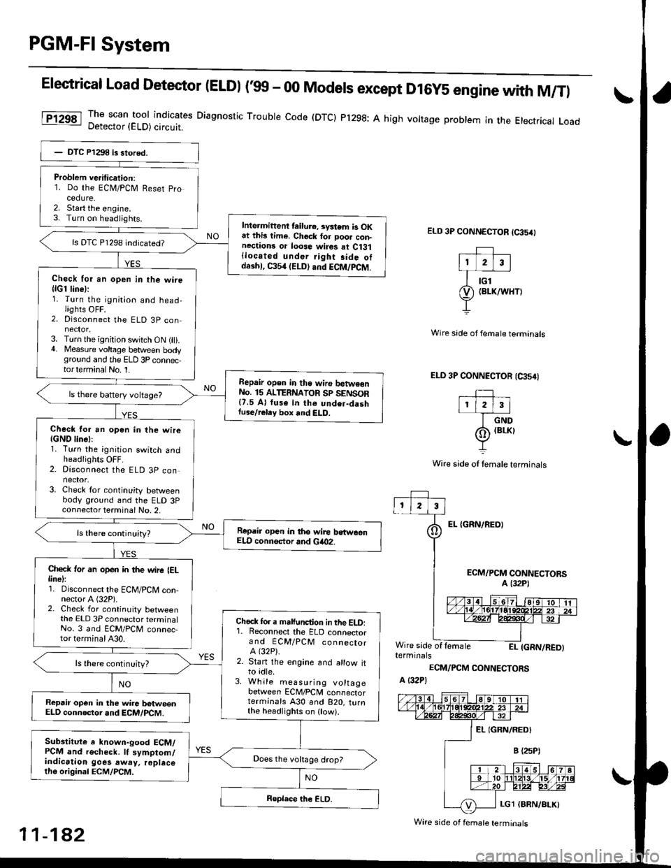
Elestrical Load Detector (ELDI ('99 - 00 Models except D16y5 engine with M/Tl
The scan tool indicates Diagnostic Trouble code (DTCI Pl298: A high vottage problem in the Etectrical LoadDetector (ELD) circuit.
ELD 3P CONNECTOR (65/0
EL {GRN/REOI
Wire side of fernale terminals
ELD 3P CONNECTOR (CA54I
TIr l2l3l
I crvo
(o) (BrKr
Y
Wire side of lemale terminals
ECM/PCM CONNECTORSA (32P1
Wire side of lemaleEI- IGRN/RED)terminals
ECM/PCM CONNECTORS
A {32P)
Problem ve.itication:1. Do the ECN4/PCM Reset pro
cedure.2. Start the engine.3- Turn on headiights.Inte.mittent teilu.e, svstem is OKat this lime. Chock for Door con-nections or loose wires at Ci31{located under Jight side otdaihl, C354 (ELD) and ECM/PCM.
ls DTC P1298 indicated?
Check for an open in the wire{lG1 line}:1. Turn the ignition and head-lights OFF.2. Disconnect the ELD 3P con
3. Turn the ignition switch ON (ll).4. Measure voltage between bodyground and the ELD 3P connec-torterminalNo. 1.
Repair opon in tho wiro batwe€nNo. 15 ALTERNATOR Sp SENSOR{7.5 A} fuse in th6 undor-dashIuse/reley box and ELD.
ls there battery voltage?
Check for an open in the wiro{GND linel:1. Turn the ignition switch andheadlights OFF.2. Disconnect the ELD 3P connector.3. Check for continuity betweenbody ground and the ELD 3Pconnector terminal No. 2,
Repair open in the wire bstwoenELD connsctor and Gia02.
Check ,or an open in the wire IELlinel:1. Disconnect the ECM/PCM con-nector A (32P).2. Check for continuity betweenthe ELD 3P connector terminalNo. 3 and ECM/PCM connec-tor terminal A30.
Chock fo. a malfunction in the ELD:'1. Reconnect the ELD connectorand ECM/PCM connectorA (32P).
2. Stan the engine and allow itto idle.3. While measuring voltagebetween ECM/PCM connectorterminals A30 and B2O, turnthe headlighrs on ow).
ls there continuity?
Repsir op€n in the wire betweenELD connector and ECM/PCM.
Substitute a known-good ECM/PCM and recheck. lf symptom/indication goes away. replacelh6 original ECM/PCM.
Does the vokage drop?
Wire side of f€male terminals
11-182
Page 460 of 2189
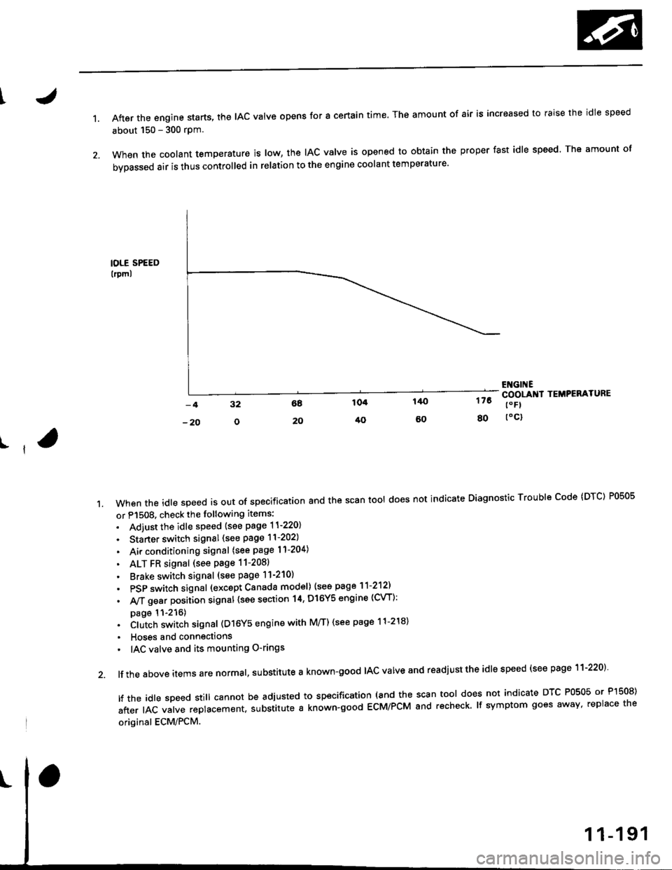
1.After the engine starts, the lAc valve opens for a certain time. The amount of air is increased to raise the idle speed
about 150 - 300 rpm.
When the coolant temperature is tow, the IAC valve is opened to obtain the proper fast idle speed. The amount of
bypassed air is thus controlled in relation to the engine coolant temperature'
IOLE SPEED
lrpml
176
80
ENGI ECOOLANI TEMPERATURE
t" Fl
toc)
ll
't.Whentheid|espeedisoutofspeciiicationandthescantoo|doesnotindicateDiagnosticTroub|ecode(DTc)P0505
or P1508. check the following items:
. Adiust the idle speed {see page 11-220}
. Starter switch signal (see page 11-202)
. Air conditioning signal (see page l1-204)
. ALT FR signal (see Page 11-2081
' Brake switch signal (see page 11-210)
. PSP switch signal (excapt Canada model) (see page 11-212)
. A,/T gear position signal {see section 14, Dl6Y5 engine (CVT):
page 11-216). Clutch switch signal (D16Y5 engine with M/T) (see page 11-218)
. Hoses and connections
' IAC valve and its mounting O-rings
lf the above items are normal, substitute a known-good IAC valve and readjust the idle speed (see page 11-220)
|ftheid|espeedsti||cannotbeadjustedtospecification(andthescantoo|doesnotindicateDTcP0505orP]50S)
after IAC valve replacement. substitute a known-good ECM/PCM and recheck. lf symptom goes away, replace the
original ECM/PCM.