1998 HONDA CIVIC main fi
[x] Cancel search: main fiPage 1918 of 2189
Cruise Control
(
UNDER.DASHFUSE/RELAYBOXI t FUSE i4| (CBUISE CO{TAOL)
i f tlfl*t., s"" P *",a H DistribulDn,
L--g----r9101_
".,."11[ftT:{.
! i,*f+*l
f:L[
SeeDash andConsoleLights
"-T[_
CRUISECONTROLMAINswtTcH
\fa
SeeDash andConsoleLights
I
'r
Lr cRN I I
I """I
I
*"1
rt
,. L----- ---3-l
i--- r#e
-ffi$r------(
llL------- --------J
"oN"
It{otcAToR
depressed. f--
Open withbrake pedal
34
Page 1922 of 2189
Gruise Control (cont'd)
- How the Circuit Works
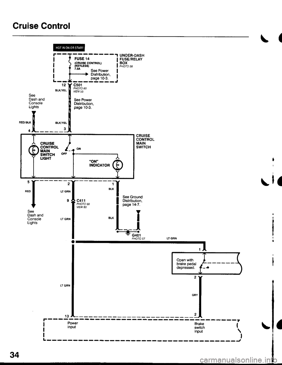
The cruise control system uses mechanical and
electrical devices to maintain the car's sDeed at a
setting selected by the driver.
System Description
The cruise control unit receives command signals
from the crurse control main switch and the cruise
control SeVResume switch. With the ignition switch
in ON (ll) or START (lll), voltage is provided to the
cruise control main switch through fuse 14. When
you push the switch to ON, power is provided to the
cruise control unit and the brake switch.
The cruise control unit receives information about
operating conditions from the brake switch, the
vehicle speed sensor (VSS), and the clutch switch
(manual transmission) or the A,/T gear position
switch (automatic transmission). The cruise control
unit then sends signals to the cruise control actuator
which regulates the throttle position to maintain the
selected speed. The conlrol unit compares the
actual speed of the car to the selected speed. The
control unit then uses the result of that comoarison
to open or close the throttle.
The brake switch releases the system's control of
the throttle at the instant you press on the brake
pedal. The switch sends a signal to the control unit
by removing power from the normally closed brake
input (GRY wire), and providing power at the
normally open brake input (GRN/vVHT wire). The
control unit responds by allowing the throttle to
close. The clutch switch or the A,/T gear position
switch sends a "disengage" signal to the control unit
that also allows the throttle to close.
The cruise control system will set and automatically
maintain any speed above 25 mph (40 km/h). To set
it, make sure the main switch is on and the switch
indicator is on. Then, after reaching the desired
speed, press the SET switch. This sends a "set"
signal to the cruise control unit which, in turn,
controls the cruise control actuator to maintain the
set speed.
When you push the SET switch and the cruise
control system is on, the "cruise control" ON
indicator lights up.
34-4
(
You can cancel the cruise control system by
turning the main switch off . This removes power to
the control unit and erases the set speed from
memory. lf the system is disengaged temporarily
by the brake switch, or clutch switch, and the car's
speed is still above 25 mph, press the resume
switch: the car will automatically return to the
previously set speed.
For gradual acceleration without pressing the
accelerator pedal, push the RESUME switch and
hold it there. This will send an "acceleration" signal
to the control unit. When you release the switch, the
system will be reprogrammed for the new speed. To
slow the car down. oush the SET switch in and hold
it there. This sends a "deceleration" signal to the
control unit, causing the car to coast. When the
desired speed is reached, release the SET switch.
This reprograms the system tor the new speed.
Refer to the Service Manual (Section 23, Electrical)
tor specific tests or troubleshooting procedures.
(
a
Page 1924 of 2189
![HONDA CIVIC 1998 6.G Workshop Manual @@
i t FusE 13
LJ::-i1":--.i
---1 UNDET
| | ryql* !5ts?n| ) iL" lir:,o,
rT ILJ---------J
--1 UNDER.DASH T ---1 UNDER-HOOD
i l$5ffif{61 !F[]::* itte*- l"l;?::*
L-g----- ---Y---J3 r-----
------- HONDA CIVIC 1998 6.G Workshop Manual @@
i t FusE 13
LJ::-i1":--.i
---1 UNDET
| | ryql* !5ts?n| ) iL" lir:,o,
rT ILJ---------J
--1 UNDER.DASH T ---1 UNDER-HOOD
i l$5ffif{61 !F[]::* itte*- l"l;?::*
L-g----- ---Y---J3 r-----
-------](/manual-img/13/6068/w960_6068-1923.png)
@@
i t FusE 13
LJ::-i1":--.i
---1 UNDET
| | ryql* !5ts?'n| ) iL"' li'r:,o,
rT ILJ---------J
--1 UNDER.DASH T ---1 UNDER-HOOD
i l$5ffif{61 !F'[]:':'* itte*- l"l;?::*'
L-g----- ---Y---J3 r-----
---------;r
".* I veuar-r< |, t_____ _1ft9#;,,
"* | ;-{ 8pfitli*| ".'"'* |
n"""
l----l .rr^ Page 14 1
-Fliirn"r"a-rq) 1' i====f:a&l?f''inarsra-rzr
"*l w;?"* ! .._ _ .l .- " .l *.*- I #it;;;--
-
lara-i-�-�'' i I @DP':,-rt
r=- 9,lo,l' o.,., I *ol- --t PowER-(rGPr) rrcP2lI TRAIN
Countersl€lt so€€d
sbneor
lJt
"":I ""1I BRNJELX
"r, | "'0 I
!-
-CIG; - - - - - - - -*-r- - 1 PowERTRAIN
t sensor t"r'ii. | .c.gl,rfgL
I gourd ground I F;-r,r;*L------- J iuoro ea
Mainshaftspoedsensorinpd
Power input
#lvrrwzo
CONTROLMODULE(PCM)PHOTO 86
(NM) (PG1) {P62) {LG0 (LG2)
":[
;{ ]1
::l -X ;;
rfl lfi* *T'r+*
| | |
:T'-jru,,L#, il
3.[iF;" H ;,$5*" I
n:'r:T'"'uo
l #lt':.See GrourdDisttlbution,page 14.
(cont'd)
BRN/BLKBFN/BLK
39-1
Page 1936 of 2189
![HONDA CIVIC 1998 6.G Workshop Manual ?uTii------lUNDER.OASHFUSE/RELAYBOX
UNDER-HOODFUSE/RELAYBOXfI,€! PtfiP
f#rntt)See PowerDistribution,
iT;;*-l
rr:_i
y;lftr,.:{
page 10-2.tJ---------J" Y 3,,t"?:"""""T
[]:.
i-?;;ffi;
i_f___
PGM- HONDA CIVIC 1998 6.G Workshop Manual ?uTii------lUNDER.OASHFUSE/RELAYBOX
UNDER-HOODFUSE/RELAYBOXfI,€! PtfiP
f#rntt)See PowerDistribution,
iT;;*-l
rr:_i
y;lftr,.:{
page 10-2.tJ---------J" Y 3,,t"?:"""""T
[]:.
i-?;;ffi;
i_f___
PGM-](/manual-img/13/6068/w960_6068-1935.png)
?uTi'i'------lUNDER.OASHFUSE/RELAYBOX
UNDER-HOODFUSE/RELAYBOXfI,€! PtfiP
f#rntt)See PowerDistribution,
iT;;*-l
rr:_i
y;lftr,.:{'
page 10-2.tJ---------J" Y 3,,t"?:"""""T
[']':.
i-?;;ffi;
i_f___
PGM-FIMAINRELAY
;;II
;;;I
c't0'l
vtEw 28
TI
":{
c130Oerminals l4-17)
vlEw 52
I . (rGP1) i 1rGP2) - I
Power input
..���������������
SeePGM,FI
POWER.TRAINCONTROLMODULE(PcM)PHO|O 86
(cont'd)
\!
CW hansm|ssion_ control solonoids Ground I
t (HLC LS-) THLCLS+) (SCLS-) (SCLS'I iSH LS I rSHLS+j ISOLINHI lPGr) (PO2) (LG1) rLG2r IL-------i:---- ---------J
-T1
Tj
:1 ;
lruffil
GRNBLII
cl16(Terminals8-14)
vlEW 39BLK
CVTTRANS.MISSIONSOLENOID
See GroundDistribution,page 14-2.
BRN/BLK
PH.PL START SHtF'CONTROL CLUTCH CONTNOLUN€AR CONTNOL LINEARSOLENOID UI{EAR SOLENOIDsoLEltotD
:_-:_-___1
-t
1-! |
Ti11:a__J
BRN/BLK
39-13
Page 1945 of 2189
- How the Circuit Works
The anti-lock brake system (ABS) prevents locking
of the wheels as a result of heavy braking and/or
poor lraction. A vehicle with locked wheels cannot
be steered. The anti-lock brake system controls the
application of the brakes, allowing the driver to
maintain control of the steering.
Under anti-lock conditions, the antilock brake
system (ABS) modulates the pressure of the brake
tluid to each brake caliper. This system is a four
channel system: the pressure at each caliper is
controlled independently of the pressure al any
other caliper. Whenever a wheel is likely to lock
dunng braking, the anti-lock brake system
modulates the brake oressure at that wheel. When
the brake pressure is reduced to the point where
there is no longer any possibility of wheel locking,
the system returns to the conventional braking
system mode of operation.
Battery voltage is applied at all times through fuse
63 to the ABS control unit. When the ignition switch
is in ON (ll), battery voltage is supplied to the
control unit through fuse 16. The control unit is case
grounded. Inputs are received from the brake switch
and the individual wheel sensors located at each
wheel. The ABS control unit uses these inputs to
control the modulator solenoid unit. The solenoids
adjust the hydraulic pressure applied to each
calioer.
The ABS control unit has a self-diagnosis function.
When the control unit detects a fault, it turns on the"ABS" indicator and disables the anti-lock brake
system. lf the fault is not in the conventional braking
system, the brakes will continue to operate normally
but without the anti-lock feature.
Refer to the Service Manual (Section '19,
Anti-Lock Brake System) for specific tests or
troubleshooting procedures.
44-3
Page 1980 of 2189
Gauges (cont'd)
- How the Gircuit Works
When the ignition switch is in ON (ll) or START (lll),
battery voltage is supplied through fuse 25 to the
gauges in the gauge assembly.
Speedometer and Odometer
The odometer and soeedometer drive circuits
receive pulses from the vehicle speed sensor
(VSS). The pulse rate increases as the car
accelerates. The frequency and duration of these
input pulses are measured and displayed by the
speedometer, odometer and tripmeter.
Tachometer
The tachometer drive circuit receives pulses from
the ignition control module (lCM) in the distributor
assembly or the ECM/PCM. The solid-state
lachometer then displays these pulses as engine
speed. For each 200 pulses per minute from the
ignition control modul€ (lCM) or the ECM/PCM, the
tachometer displays 100 RPM.
Engine Coolant Temperature Gauge
The engine coolant temperature gauge has two
intersecting coils wound around a permanent
magnet rotor. Voltage applied to the coils, through
fuse 25, generates a magnetic lield. The magnetic
field, controlled by the coolant temperature sending
unit, causes the rotor to rotate and the gauge
needle to move. As the resistance in the sending
unit varies, current through the gauge coils
changes. The gauge needle moves toward the coil
with the strongest magnetic field.
The 6ngine coolant temperature sending unit's
resistance varies from about 137 ohms at low
engine temperature to between 3H6 ohms at high
temperature (radiator fan running).
Refer to the Service Manual (Section 23, Electrical)
for specific tests or troubleshooting procedures.
81-2
(
Fuel Gauge (All except cX)
The fuel gauge has two intersecting coils wound
around a permanent magnet rotor. Voltage applied
to the coils, through tuse 25, generates a magnetic
field. The magnetic field, controlled by the fuel
gauge sending unit, causes the rotor to rotate and
the gauge needle to move. As the resislance in the
sending unit varies, current through the gauge coils
changes. The gauge needle moves toward the coil
with the strongest magnetic field.
The fuel gauge sending unit's resistance varies
from about 2-5 ohms at full, to about 110 ohms at
empty. When you turn the ignition switch off, the
gauge remains at the last reading until you turn the
ignition switch to ON (ll) or START (lll) again,
Refer to the Service Manual (Section 23, Electrical)
for specific tests or troubleshooting procedures.
Fuel Gauge (GX)
The fuel gauge has two intersecting coils wound
around a permanent magnet rotor. Voltage applied
to the coils, through fuse 25, generates a magnetic
field. The magnetic field, controlled by the PCM,
causes the rotor to rotate and the gauge needle to
move. The PCM calculates the gas quantity in the
fuel tank by using the fuel pressure value detected
by the tuel tank pressure sensor and the fuel
temperature value detected by the fuel tank
temperalure sensor, and outputs the signal to the
gauge assembly. The gauge needle moves toward
the coil with the strongest magnetic field.
When you turn the ignition switch off , the gauge
remains at the last reading until you turn the ignition
switch to ON (ll) or START (lll) again. When the
PCM detects a malfunction with the fuel pressure or
temperature, or detects a gas leak, the PCM
reduces the fuel meter to 0.
Refer to the Service Manual GX Supplement
(Section 11 , Fuel and Emissions) for specific tests
or troubleshooting procedures.
a
a
Page 1989 of 2189
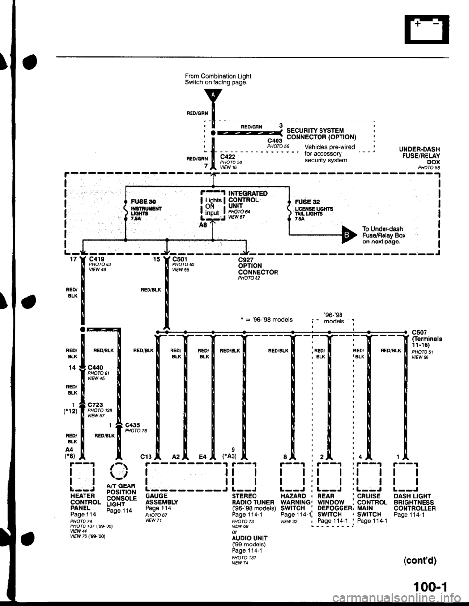
UNDER.DASHFUSE/RELAYBOXPHOTO 58
I
I
I
I
I
I
FUSE 32tpE SE UGfiTStan r|{rs7,54
r--1 l ?EqnATEOI uohts I co rRoL; OFI I UNIT
! input ! im?,t
I
1f12)
To Under-dashFus€/Rglay 8oxon n6xl pag€.
-J---------rt--- ----Jc4r9 15 Y C501 c927PHOfO 6iOPTIONCONNECTORPHOTO 62
nEo/ALK
REO/ALK
* = '96-'98 models
*1[
"-"'['**,.1
_[ *[ ,*,
, FED/
I t:t t;t I
I l:l I ll IL--J ; L--J .L--J
HAZARD , REAR ' CRUISEWARNING. WINDOW :CONTROLSwITcH . DEFoGGER; MAINPage 114-1; SWITCH ' SWITCHvtEv/ 32 , Page114-1 'Pago114-1
c507(Ierminals11n6)
vtEw 56REO/EIK
14
RED/BLK
C't40PHOTO El
c723PHOfO 138
r--1 ;-r
| |ii | il || | | ll I: : A"rr GEAR !------J L--J
EEil'J",- p$i+bd'i 3333fi".' ilB?o'?u"."PANEL Eli"ira Page114 (96-'98 models)Page 114 PHoro 6, Page 1 14.1pHOfO 71 VIEW 71 pHOfO 73PHO|O 1i7 (g9'@l V|EW 6AwEtt/ 41 otv/Ew761ee-oo)
irril?.rJllPage 114-1PHOfO 13/vtEw 74
tl
tl
OASH LIGHTBRIGHTNESSCONTROLLERPage 114-1
(cont'd)
FIJSE l0
100-1
Page 2006 of 2189
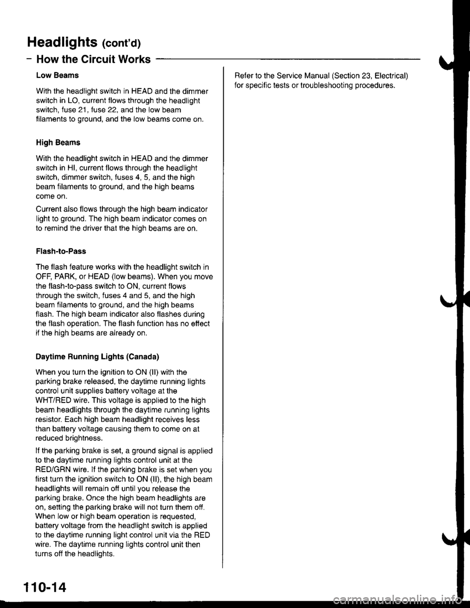
Headlights (cont'd)
- How the Circuit Works
Low Beams
With the headlight switch in HEAD and the dimmer
switch in LO, current tlows through the headlight
switch. fuse 21 . fuse 22. and the low beam
tilaments to ground, and the low beams come on.
High Beams
With the headlight switch in HEAD and the dimmer
switch in Hl, current flows through the headlight
switch, dimmer switch, fuses 4, 5, and the high
beam filaments to ground, and the high beams
come on.
Current also llows through the high beam indicator
light to ground. The high beam indicator comes on
to remind the driver that the high beams are on.
Flash-to-Pass
The flash feature works with the headlight switch in
OFF, PARK, or HEAD (low beams). When you move
the flash-to-pass switch to ON, current flows
through the switch, fuses 4 and 5, and the high
beam filaments to ground, and the high beams
flash. The high beam indicator also flashes during
the flash operation. The flash function has no effect
if the high beams are already on
Daytime Running Lights (Canada)
When you turn the ignition to ON (ll) with the
parking brake released, the daytime running lights
control unit supplies battery voltage at the
WHT/RED wire. This voltage is applied to the high
beam headlights through the daytime running lights
resistor. Each high beam headlight receives less
than battery voltage causing them to come on at
reduced brightness.
lf the parking brake is set, a ground signal is applied
to the daytime running lights control unit at the
RED/GRN wire. lf the parking brake is set when you
first turn the ignition switch to ON (ll), the high beam
headlights will remain off until you release the
parking brake. Once the high beam headlights are
on, setting the parking brake will not turn them ofi.
When low or high beam operation is requested,
battery voltage from the headlight switch is applied
to the daytime running light control unit via the RED
wire. The daytime running lights control unit then
turns off the headlights.
Refer to the Service Manual (Section 23, Electrical)
for specific tests or lroubleshootrng procedures.
110-14