Page 991 of 2189
Transmission Housing/Lower Valve Body Assembty
Removal
NOTE:
. Clean all parts thoroughly in solvent or carburetor cleaner, and dry with compressed air.. Blow out all passages.
. When removing the lower valve body, replace the followingl- O-rings- ATF pan gasket- Sealing washers
DOWEL PIN
ATF STRAINER
6 x 1.0 mm BOLT
ATF PAN GASKETReplace.
ATF COOLER INLET LINEBRACKET BOLT8 x 1.25 mm
ATF COOI..ER INLET LINE
O.RINGReplace.
SOLENOIO HARNESS CONNECTOR
6 x'1.0 mm BOLT
LOWER VALVE BODY ASSEMBLY
6 x 1.0 mm BOLT
14-314
6 x 1.0 mm EOLT
Page 992 of 2189
l.
'1.
2.
5.
6.
7.
Remove the ATF cooler inlet iine bracket bolt'
Remove the ATF cooler outlet line
Remove the ATF pan (fourteen bolts).
Remove the ATF strainer {two bolts)
Remove the one bolt securing the solenoid harness
connector, then push the connector.
Remove the lower valve body (eight bolts)
Clean the inlet opening of the ATF strainer thoroughly
with compressed air, then check that it is in good
condition, and the inlet opening is not clogged'
ATF STRAINER
INLET OPENING
Replace the ATF strainer if it is clogged or damaged
NOTE: The ATF strainer can be reused it it is not
clogged.
2c'
c;2 ar\
14-315
Page 1022 of 2189
Transmission
Reassembly (cont'dl
65 lnstall the solenoid harness connector with a new O-ring (one bolt), then install the lower valve body assembly withthree dowel pins (eight bolts).
66. Install the ATF strainer with a new O-ring (two bolts).
67. lf necessary, assemble the ATF pan, ATF filter, and the ATF cooler inlet line (see page 14_303).
68. Install the ATF pan with the two dowel pinsand a new ATF pan gasket (fourteen bolts).
69. Install the ATF cooler inlet line bracket bolt.
70. Installthe ATF cooler outlet line with the line bolt and new sealing washers.
6x1.0mm12 N.m 11.2 kgf.m,8.7 rbtft)DOWEL PINS
ATF STRAINER
DOWEL PINS
ATF PAN,/ATF FILTER/ATF COOLER INLETLINE ASSEMELY
@
@
C4
CONNECTOE
6x1.0mm12 N.m {1.2 kgf.m,8.7 tbtftl6x1.0mm12Nm11.2kgl.m,8.? tbf.ft)
LOWER VALVE BODYASSEMBLY
6x1.0mm12 N.m 11.2 kgf.m,8.7 tbt.ft)
ATF COOI.ER INI.ITLINE BRACKET BOLTI x 1.25 mm26 N.m (2.7 kgt.m, 20 lbf.ft)
ATF COOLER OUTI.IT LINE
14-346
Page 1024 of 2189

Transmission
Installation
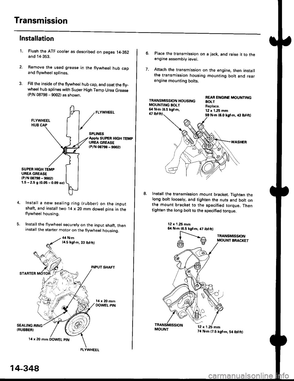
Flush the ATF cooler as described on pages 14-352and 14-353.
Remove the used grease in the flywheel hub caDand flywheel splines.
Fill the inside of the flywheel hub cap, and coat the fly-wheel hub splines with Super High Temp Urea Grease(P/N 08798 - 9002) as shown.
L
SEALING RING{RUEBER)
SPLINESApply SUPEB HlcH TEMPUREA GREASElPlN 08798 - 90O2t
SUPER HIGH TEMPUREA GREASE(P/N 08798 - !)00211.5-2.5 g 10.05-0.t9 oz)
Install a new sealing ring (rubber) on the inoutshaft, and install two '14 x 20 mm dowel Dins in theflywheel housing.
Install the flywheel securely on the input shaft, theninstallthe starter motor on the flywheel housing.
4,1Nmla.5 kgt.m, 33 tbt.ft)
INPUT SHAFT
STARTER
l4 x 20 mm DOWEL ptN
.4;i "lrj
,i rr,"r., ., a
14-348
FLYWHEEL
MOUI{T74 N.m (7.5 tstm,5a tbtftt
6. Place the transmission on s jack, and raise it to theengine assembly level.
7. Anach the transmission on the engine, then installthe transmission housing mounting bolt and rearengine mounting bolts.
TRANSMISSION HOUSINGMOUNTING BOIT6,1 N.m 16.5 kgl.m,47 tbtttl59 Nrn {6.0 kgl.m. ,€ lbt ftl
WASHER
lnstall the transmission mount bracket. Tighten thelong bolt loosely, and tighten the nuts and bott onthe mount bracket to the specified torque. Thentighten the long bolt to the specified torque.
REAR ENGINE MOUNTINGBOLTReplace.12 x 1.25 mm
12x 1.25 mn6,r N'm 16.5 kgtm,47 tbtftl
l-".--..-,^
G\V
TRANSMISSONMOUNT BRACKET
12 x 1.25 mn
Page 1025 of 2189

l.
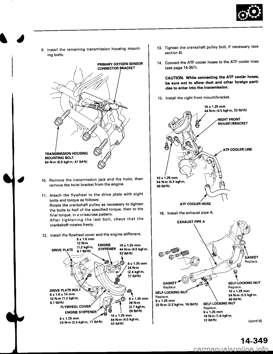
9. Install the remaining transmission housing mount-
ing bolts.
PRIMARY OXYGEN SENSOR
Remove the transmission jack and the hoist. then
remove the hoist bracket from the engine'
Attach the flvwheel to the drive plate with eight
bolts and torque as follows:
Rotate the crankshaft pulley as necessary to tighten
rhe bolts to half of the specified torque, then to the
final torque, in a crisscross pattern.
After tightening the last bolt. check that the
crankshaft rotates freelY.
10.
11.
12. Install the flywheel cover and the engine stiffeners
DRIVE
6xl.0mm12 N.m
- l12 kgf'm'rE 8.7 tbf.ftl
ENGINESTIFfENEB10 x 1.25 mmart N.m la.s kgt.m,33 tbtftt
8 x 1.25 mm24 N.m(2.1 kgf'm,17 tbt.ftt
DRIVE PI.ATE BOLT
6x1.0x14mm12 N.m {1.2 kgt m.
8.7 lbf,ftl8 x 1.25 mm26 N.m
12.7 kqfin,20 rbt'ftlFLYUTHEEL
ENGINE STIFFENER
8 x 1.25 mm10 x 1.25 mmr,a N.m {4,5 kgf m,
33 tbf.ftl
TRANSMISSION HOUSING
MOUNNNG BOLT
6il N.m {6.5 kgf.m, 47 lbf'ftl
24 N.m (2.4 kgt'm, '17 lbf'ftl
22 N.m t2.2 kgl m, 16lbf'ftl
14-349
13.
14.
Tighten the crankshaft pulley bolt, if necessary (see
section 6).
Connect the ATF cooler hoses to the ATF cooler lines
(see page 14-357).
CAUTION: Whilo connecting the ATF cooltr hGes,
b€ sure not lo allow dust and other loreign parti-
cles to entg. into the transmission.
15. Installthe right front mounvbracket'
10 x 1.25 mm
a,r N.m {4.5 kgf'm,33 lbt ftl
RIGHT FRONTMOUNT/BRACKET
ATF COOLER LINE
10 x 1 .25 mm54 N.m {5.5 kgt'm,
4{) tbl.ftt
ATF COOI,TR HOSE
16. Installthe exhaust PiPe A.
EXHAUST PIPE A
GASKETReplace.
@
\SELF.LOCKING NUTReplace.10 x 1.25 mm5/a N.m {5.5 kgt m,irc lbf.ft)
(cont'dl
*s$o
oor*rr-@Replace.
SELF.LOCKINGReplace.8 x 1.25 mmSELF.LOCKING NUT
Replace.8 x 1.25 mm16 N.m {1.6 kgl'm,12 tbl.ftt
Page 1028 of 2189

Transmission
Gooler Flushing
@ To prevent iniury to face and eyes, alwayswear safety glasses or a tace shield when using thetransmission flusher.
NOTE: This procedure should be performed before rein-stalling the transmission.
'1. Check the tools and hoses for wear and cracks before
using. lf wear or cracks are found, reDlace the hoses
before using.
4.
Using the measuring cup. fill the tank with 2,1 ounces(approximately 2/3 full) of biodegradable flushingfluid (J35944 - 20). Do not substitute with any otherfluid. Follow the handling procedure on the fluidcontatner.
Secure the flusher filler cap, and pressurize the tankwith compressed air to between 5S0 - 829 kpa (5.6 -
8.45 kgf/cm'�, 80 - 120 psi).
NOTE: The air line should be equipped with a watertrap to ensure a dry air system,
Hang the tool under the vehicle.
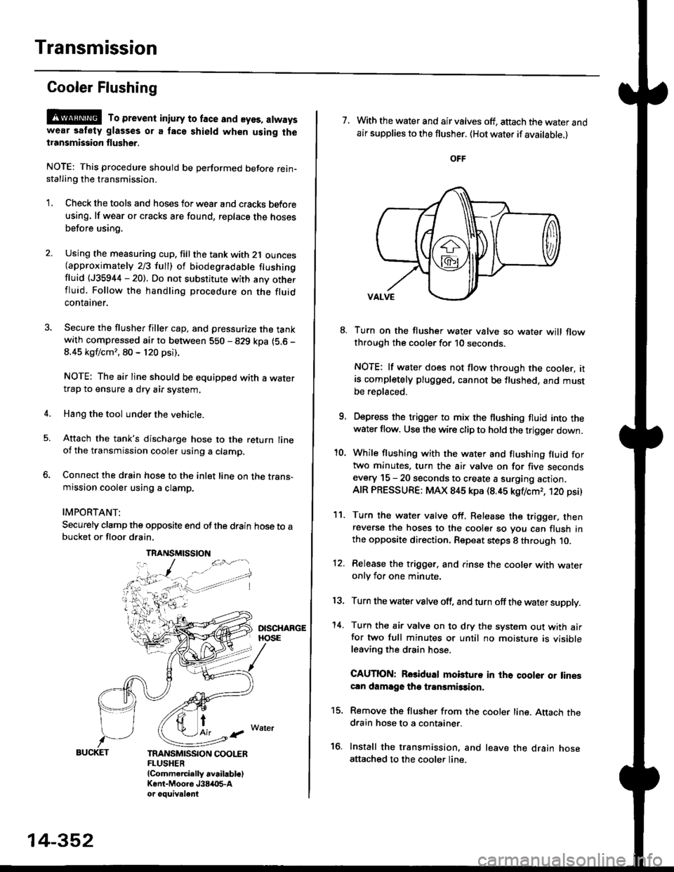
Attach the tank's discharge hose to the return lineoi the transmission cooler using a clamp.
Connect the drain hose to the inlet line on the trans-mission cooler using a clamp.
IMPORTANT:
Securely clamp the opposite end ofthe drain hose to abucket or floor drain,
t
TRANSMISSION COOLERFLUSHER{Commercially available)Kent-Moore J384O5-Aor oouivalent
TRANSMISSION
14-352
7. With the water and air valves off, attach the water andair supplies to the flusher. (Hot water if available.)
8. Turn on the flusher water valve so water will flowthrough the cooler for 10 seconds.
NOTE: lf water does not flow through the cooler, itis completely plugged, cannot be flushed, and mustbe replsced.
9. Depress the trigger to mix the flushing fluid into thewater flow. Use the wire clip to hold the trigger down.
'10. While flushing with the water and flushing fluid fortwo minutes. turn the air valve on for five secondsevery 15 - 20 seconds to create a surging action.AIR PRESSURE: MAX 845 kpa (8.45 kgflcmr, 120 psi)
11. Turn the water valve off. Release the trigger, thenreverse the hoses to the cooler so you can flush inthe opposite direction. Repeat steps 8 through 10.
12. Release the trigger. and rinse the cooler with wateronly for one minute.
13, Turn the water valve off, and turn off the water supply.
'14. Turn the air valve on to dry the system out with airfor two full minutes or until no moisture is visibleleaving the drain hose.
CAUTION: Rosidual mobturo in the qooler or linescln damage the transmission,
15. Remove the flusher from the cooler line. Attach thedrain hose to a container.
16. Install the transmission. and leave the drain hoseattached to the cooler line.
Page 1029 of 2189
![HONDA CIVIC 1998 6.G Workshop Manual l.
17.Make sure the transmission is in the E] position.
Fill the transmission with cvT Fluid, and run the
engine for 30 seconds or until approximately 0 95 {
(1.0 US qt.,0.8 lmp qt.) is discharged.
Re HONDA CIVIC 1998 6.G Workshop Manual l.
17.Make sure the transmission is in the E] position.
Fill the transmission with cvT Fluid, and run the
engine for 30 seconds or until approximately 0 95 {
(1.0 US qt.,0.8 lmp qt.) is discharged.
Re](/manual-img/13/6068/w960_6068-1028.png)
l.
17.Make sure the transmission is in the E] position.
Fill the transmission with cvT Fluid, and run the
engine for 30 seconds or until approximately 0 95 {
(1.0 US qt.,0.8 lmp qt.) is discharged.
Remove the drain hose, and reconnect the cooler
return hose to the transmission (see page 14-355)
Refill the transmission with CVT Fluid to the proper
level (see page 14-299).
18.
'19.
.l ,
TOOL MAINTENANCE
1. Empty and rinse after each use. Fill the can with water
and pressurize the can. Flush the discharge line to
ensure that the unit is clean.
2, lf discharge liquid does not foam, the orifice may be
blocked.
3. To clean, disconnect the plumbing from the tank at
the large couPling nut.
FILTER
\
\- 0--D
i
I
O.RING
Remove the in-line tilter from the discharge side and
clean if necessary'
The fluid orifice is located behind the filter. Clean it
with the pick stored in the bottom of the tank han-
dle. or blow it clean with air. Securely reassemble
all parts.
COUPLINGNUT
II
-@q
\ORIFICE
FILLER CAP
14-353
Page 1033 of 2189
Shift Indicator PanelATF Gooler/Hoses
Adjustment
1.Check that the index mark on the indicator aligns
with the E mark on the shift indicator panel when
the transmission is in NEUTRAL.
lf not aligned, remove the front console {see section
20).
Remove the shift indicator panel mounting
and adjust by moving the panel.
NOTE: Whenever the shift indicator panel is removed,
reinstallthe Danel as described above.
It,
14-357
lnstallation
1. Installthe ATF cooler, ATF cooler line assembly and
the ATF cooler hoses.
6x1.0mm11 N.m ('l 1 kgf.m,8.0lbl'ftlATF COOLER LINE ASSEMBLY
ATF COOLER HOSE
RADIATOR
6x1.0mm9.8 N.m 11.0 kgf'm, 7 8 lbf'ft)
ATF COOLER
Connect the ATF cooler
lines and ATF cooler. and
as shown.
hoses to the ATF cooler
secure them with the clips
1l lTf{il.T
6-8mm10.2 - 0.3 in)
33-35mm11.3 - 1.4 inl
2-1mm10.1 - 0.2 in)
2-ilmm{0.1 - 0.2 in)
ATF COOI..ER HOSES