Page 1494 of 2189

Connector ldentification and WireHarness Routing
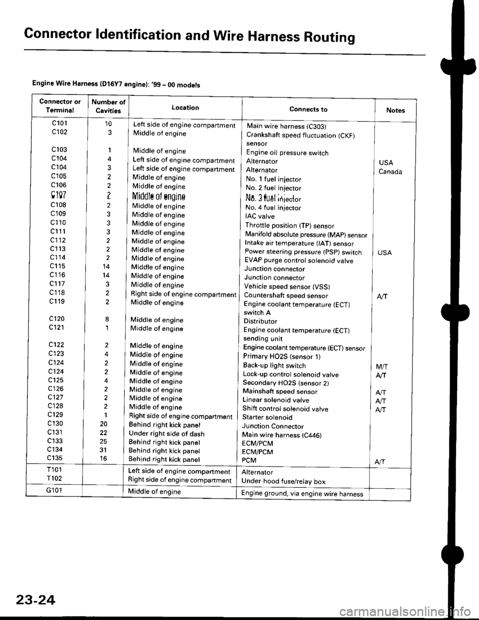
Engine Wire Harness (D15Y? engine): ,99 - OO models
c101
c102
cl03
c't04
c 104
c 105
cr 06
0107
c108
c109
c't 10
c11 r
c112
c113
c114
c115
c116
c117
cl18
c119
c120
c121
c122
c123
c124
c124
c125
c127
c128
c129
c 130
c 131
c134
c135
10
3
'I
3
?
2
3?
2
14
14
3
2
8
1
Left side of engine compartment
Middle of engine
fvliddle of engine
Left side of engine compartment
Left side of engine companment
Middle of engine
Middle of engine
Middlr ol sngins
Middle of engine
Middle of engine
Middle of engine
Middle of engine
Middle of engine
Middle of engine
Middle of engine
Middle of engine
Middle of engine
Middle of engine
Right side of engine compartment
Middle of engine
Middle of engine
Middle of engine
Middle of engine
Middle of engine
Middle of engine
Middle of engine
Middle of engine
Middle of engine
Middle of engine
Middle of engine
Right side ot engine compartment
Behind right kick panel
Under right side of dashBehind right kick panel
Behind right kick panel
Behind right kick panel
Main wire harness (C303)
Crankshaft speed fluctuation (CKF)
sensor
Engine oil pressure switch
Alternator
AlternatOr
No. l fuel injector
No.2 fuel injector
No. I fual itjecto,
No.4 fuel injector
IAC valve
Throttle position (TP) sensor
Manifold absolute pressure {MAp) sensorIntake air temperature 0AT) sensorPower steering pressure (PSp) switchEVAP purge control solenoid valveJunction connector
Junction connector
Vehicle speed sensor (VSS)
Countershaft speed sensor
Engine coolant temperature {ECT)switch A
Distributor
Engine coolant temperature (ECT)
sending unit
Engine coolant temperature (ECT) sensor
Primary HO2S (sensor 1)
Back-up light switch
Lock-up control solenoid valveSecondary HO2S (sensor 2)Mainshaft speed sensor
Linear solenoid valve
Shift control solenoid valve
Starter solenoid
Junction Connector
Main wire harness (C446)
ECM/PCM
ECM/PCM
PCM
USA
Canada
M/T
Atr
Atr
Alr
Al-|.
Left side of engine compartment
Right side of engine compartment
Middle of engineEngine ground, via engine wire harness
23-24
Page 1496 of 2189

Connector ldentification and WireHarness Routing
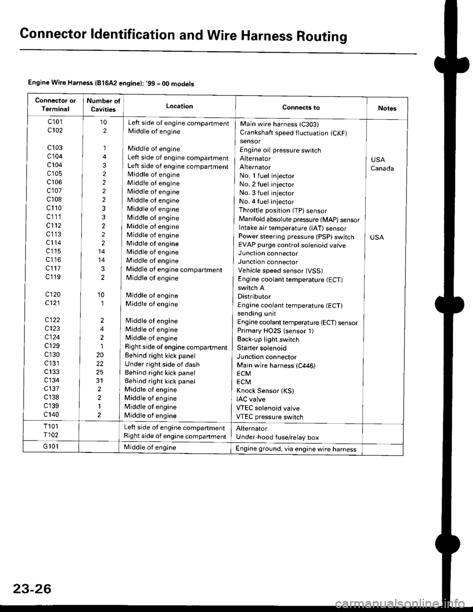
Engine Wire Harness {81642 engine}: .99 - 00 models
c 101
c102
cl03
c104
c 104
c'105
c106
cl01
c108
c110
cl11
cl12
c1'13
c114
c115
c117
cl19
c120
c121
c122
c123
c124
c129
c130
c l31
c133
c134
c137
c 138
c139
c140
Left side of engine companment
Middle of engine
Middle of engine
Left side of engine compartment
Left side of engine compartmentlvliddle of engine
Middle ot engine
Middle of engine
Middle of engine
Middle of engine
Middle of engine
Middle ot engine
Middle of engine
Middle of engine
Middle of engine
Middle of engine
Middle of engine compartment
Middle of engine
Middle of engine
Middle of engine
lMiddle of engine
Middle of engine
Middle of engine
Right side of engine compartment
Behind right kick panel
Under right side of dash
Behind right kick panel
Behind right kick panel
Middle of engine
Middle ot engine
lMiddle of engine
Middle of engine
10
2
,]
4
3
2
2
2
2
3
3
2
2
2
14
14
3
2
'10
'I
2
4
2
1
20
22
25
31
2
2
I
Main wire harness (C303)
Crankshaft speed fluctuation (CKF)
sensor
Engine oil pressure switch
Alternator
Alternator
No. 1 fuel injector
No. 2 tuel injector
No. 3 fuel injector
No. 4 fuel injector
Throttle position (TP) sensor
Manifold absolute pressure (MAP) sensorIntake air temperature (lAT) sensorPower steering pressure (PSP) swjtchEVAP purge control solenoid valve
Junction connector
Junction connector
Vehicle speed sensor (VSS)
Engine coolant temperature (ECT)
switch A
Distributor
Engine coolant temperature (ECT)
sending unit
Engine coolant temperature {ECT) sensorPrimary HO2S (sensor 1)
Back-up light switch
Starter solenoid
Junction connector
Main wire harness (C446)
ECM
ECtvl
Knock Sensor {KS)IAC valve
VTEC solenoid valve
VTEC pressure switch
USA
Canada
Left side of engine companment
Right side of engine compartment
Engine ground, via engine wire harness
Page 1581 of 2189

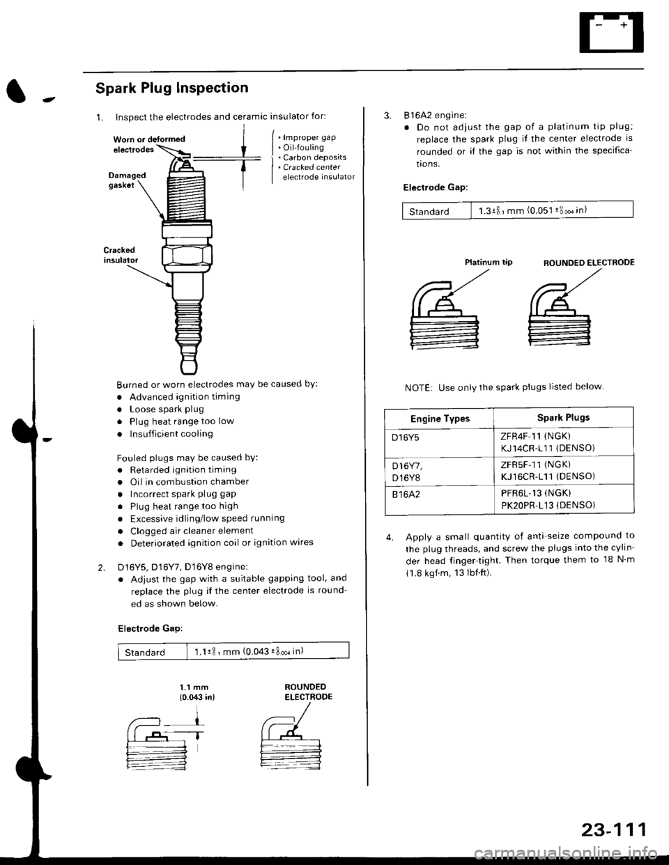
1. Inspect the electrodes and ceramic insulator for:
Spark Plug lnspection
Crackedinsulator
2.
[ . t.p,op", grp
| . Oil-fouling
i . Carbon deposits
| . Cracked center
I electrode insulator
Burned or worn electrodes may be causecl by:
. Advanced ignition timing
. Loose spark plug
. Plug heat range too low
. Insufficient cooling
Fouled plugs may be caused bY:
. Retarded ignition timang
. Oil in combustion chamber
. Incorrect spark plug gap
. Plug heat rangetoo high
. Excessive idling/low speed running
. Clogged air cleaner element
. Deteriorated ignition coil or ignition wares
D16Y5, D16Y7, D'16Y8 enginel
. Adjust the gap with a suitable gapping tool, and
replace the plug il the center electrode is round-
ed as shown below.
Electrode Gap:
1.1 mm
{o.{X:l in)ROUNDEDELECTRODE
Standard 1.1r8 ' mm (0.043i800oin)
Worn or detormed
1T
23-111
3. 816A2 engine:
. Do not adjust the gap of a platinum tip plug;
replace the spark plug il the center electrode is
rounded or it the gap is not within the specifica
tro ns.
Electlode Gap:
Standard 1.3181mm (0.051 !3oo" in)
flOUNDED ELECTROOE
',/
@_
:
Platinum tip
NOTE: Use only the spark plugs listed below
4. Apply a small quantity of anti seize compound to
the plug threads, and screw the plugs into the cylin
der head finger-tight. Then torque them to 18 N m
11.8 kgf.m, 13lbnft).
Engine TypesSpark Plugs
D16Y5ZFR4F 11 (NGK)
KJ14CR-111 (DENSOi
D16Y7,
D,I6Y8
ZFRSF-11 (NGK)
KJ16CR-111(DENSO)
81642PFR6L.13 (NGK)
PK2OPR.L13 (DENSO}
Page 1594 of 2189
Gharging System
Rear Bearing Replacement
1. Pull offthe rear bearing,
. Make sure the tips of the bearing puller jaws arethin enough to fit between the bearing and theslip rings.
. Do not reuse the bearing.
SLIP RINGSBEARING PULLER
Use a hand press to install the new bearing. Applypressure only on the inner race to avoid damaging
the bearino.
REAB BEARING
23-124
Alternator Reassembly
1. Push the brushes in, then insert a pin or drill bit(about 1.8 mm diameter) to hold them there.
Heat the rear bearing seat in the rear housing asdescribed on page 23-121. After heating, continueimmediately with assembling before the rear bear-ing seat cools completely,
Put the rear housing/stator assembly and drive-endhousing/rotor assembly together. tighten the fourthrough bolts and pull out the pin.
REARSTATOR ASSEMBLY
After assembling the alternator, turn the pulley byhand to make sure the rotor rotates smoothlv andwithout noise.
BRUSHES
THROUGH BOLT
Iq
%*z
BRUSH AOCESS HOI."E
Page 1596 of 2189
Fan Controls
Component Location Index
UNDER.HOOO
CONDENSER FAN RELAYTest, page 23-87
RADIATOR FAN RELAYTest, page 23 87
CONDENSERFAN MOTOR
TOR FAN MOTORRemoval, section 10
ENGINE COOLANTTEMPERATURE (ECTI
swtTcHRemoval, section 10Test, section l0
t lt lt lt tt l
tlTtlnr-l
mU!L-Jfl_l'1 - f-t t-_l -
I L--J L__J LJ f-----"1
o
^o
o"l
23-126
Page 1597 of 2189
IJCircuit Diagram
UNDER DASHIGNIT ON SWITCH FUSEIRELAY 8OX
6 |-;;;;lii "ir"'t*Tl-l
BLK yEL -J
GRN
III
I
\.7VECM/PCM
ENG NECOOLANTlEMPERATURE (ECT)SWTCHfclosed : Above 'l
L r99"F (93"C) _l
BLKTRED
I
I
1,,*"_
T-'
IBtK
I
I
G201
UNDER.HOOD FUSElRELAY BOX
No 41 (8041 No 42 (40A)
Page 1599 of 2189
JGau ge/lndicator/Terminal
With tachometer;
CONNECTOR "A"
{A/T GEAR POSITION INDICATOR}
Location lndex
CONNECTOR "8"
{GAUGE and INOICATOR)CONNECTOB "C"
CONNECTOR "D"
{ABS INDICATORI
SPEEDOMETER:Indicates 60 km/h at 637 rpm or
60 mph at 1,025 rpm o{thevehicle speed sensor (VSS).
A/T GEAR POSITIONINDICATORSee page 23 149
TACHOMETER:Indicates 100 rpm at200 pulses per minuteol the ignition controlmodule (lCMi.FUEL GAUGEENGINE COOLANT TEMPERATURE (ECT) GAUGE
(cont'd)
23-129
(GAUGE end INDICATORI
A1-----------+816
JlltlllulllllrL
c1 --------->c13
1ililil{ilrL
oooo o 0006^
)og @ @ o^o @ )'l |. o
Fl- - -> F5E1_ _ -->E5D1- --+05
oo/ \oo
Gauge/Sending Unit Test, page 23-142
Page 1600 of 2189
Gauge Assembly
Gauge/lndicator/Terminal Location Index (cont'd)
Without tachometer:
CONNECTOR "A"
IA/T GEAR POSITION INDICATORICONNECTOR "8"
{GAUGE and INDICATOR}CONNECTOR "C"
(GAUGE and INDICAIORI
CONNECTOR "F"
{SRS INDICATOR)CONNECTOR "D"
{ABS INDICATORI
SPEEDOMETER:Indicates 60 km/h at 637 rpm or60 mph at 1,025 rpm ofthevehicle speed sensor (VSS).
ENGINE COOLANT TEMPERATUFE (ECT) GAUGEA/T GEAR POSITIONINDICATOFSee page 23 149FUEL
A1 ------> 46
----> al4
B1. - --------------->B16
JilililHililil1
C1-- - --------..+C13
JililHililL
Oo_o-o O 0006
lus 0 0 Bu-. )
oo/ \oo
23-130
Gauge/Sending Unit Test, page 23 142