1998 HONDA CIVIC cool
[x] Cancel search: coolPage 1608 of 2189
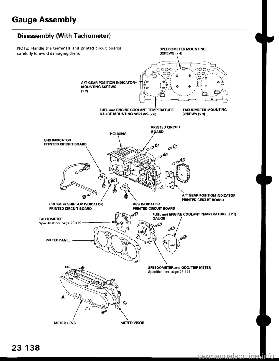
Gauge Assembly
Disassembly (With Tachometerl
NOTE: Handle the terminals and Drinted circuit boards
carefully to avoid damaging them.
A/T GEAR POSITION INDICAMOUNNNG SCREWStx 2)
FUEL and ENGINE COOLANT TEMPEMTUREGAUGE MOUNTING SCREWS {x 6,TACHOMETEB MOUNTINGSCREWS lx 3l
ao
,-ook+r
.,- ll $
t'{"{q.' ElI ..il \:r
A/T GEAR POSITION INOICAPRINTED CIRCUIT BOARD
INDICATORPRINTED CIRCUIT BOARD
@ FUEL end ENGINE COOLANT TEMPERATURE (ECTI
PRINTEO CIRCUIT
q,
6\
ABSCRUISE or SHIFT-UP INDICATORPRINTED CIRCUTT EOARD
TACHOMETERSpecilication, page 23 129
METER PANEL
booo .--:o'-..oooo.A
:-F.-sr'; "€?;"')
aFl l!
GAUGE
23-134
Page 1609 of 2189
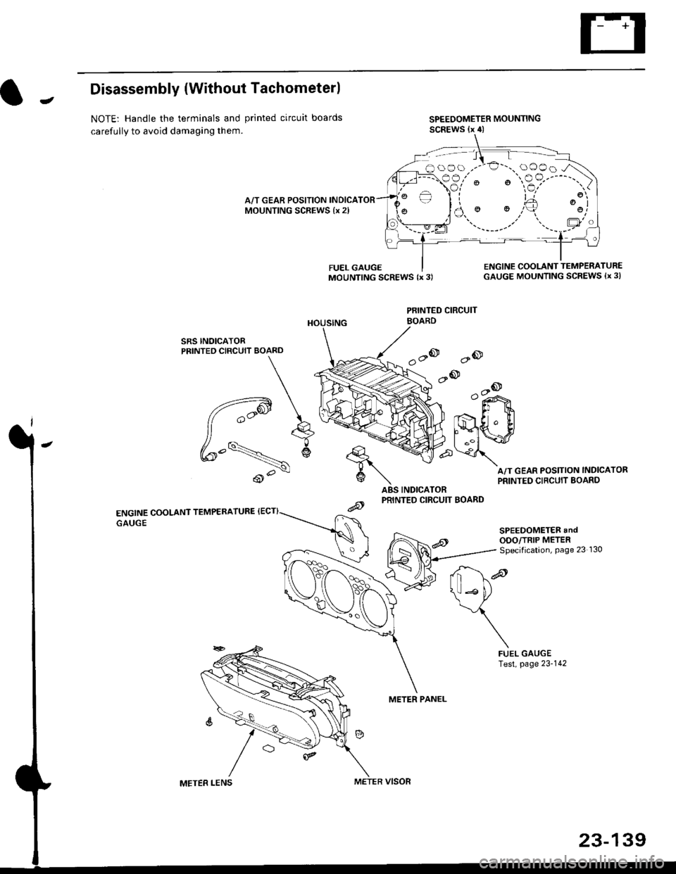
JDisassembly {Without Tachometerl
NOTE: Handle the terminals and printed circuit boards
carefully to avoid damaging them.
SPEEDOMETER MOUNTINGSCREWS (x 4)
A/T GEAR POSITION INDICAMOUNTING SCREWS {x 2l
SRS INOICATORPRINTED CIRCUIT BOARD
ENGINE COOLANT TEMPERATURE {ECT}
GAUGE
ABS INDICATORPRINTED CIRCUIT BOARD
PRINTED CIRCUIT
METER PANEL
FUEL GAUGEMOUNTING SCREWS {x 3)ENGINE COOLANT TEMPERATUR€GAUGE MOUNTING SCREWS {x 3l
A/T GEAR POSITION INDICATOR
PRINTED CIRCUIT BOARD
'a@
.-@--o
o"i^>
Er t
lmwp\
d*re
\*P
\
FUELTest,GAUGEpage 23-142
oOo ,.-'€'-., oOOo -/\
€3,'" ' "$?'----"')
)a.' '.,,'+ ':j
\ll Lto
BOARD
METER LENSMETER VISOR
23-139
Page 1746 of 2189
Precautions/Procedu res
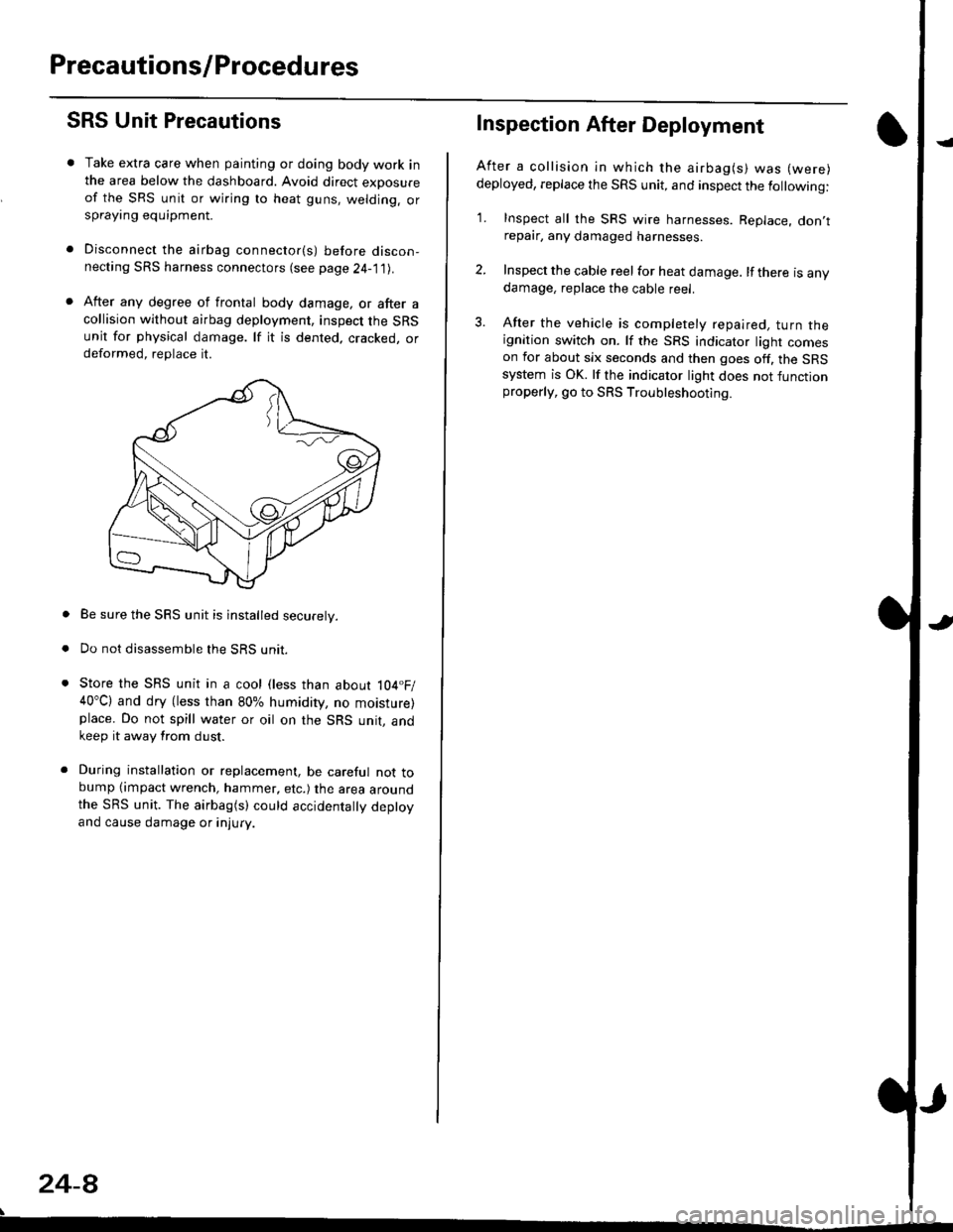
SRS Unit Precautions
Take extra care when painting or doing body work inthe area below the dashboard. Avoid direct exDosureof the SRS unit or wiring to heat guns, welding. orsprayang equipment.
Disconnect the airbag connector(s) before discon-necting SRS harness connectors (see page24-1|1J.
After any degree of frontal body damage, or after acollision without airbag deployment, inspect the SRSunit for physical damage. lf it is dented. cracked, ordeformed, replace it.
Be sure the SRS unit is installed securely.
Do not disassemble the SRS unit.
Store the SRS unit in a cool (less than about 104.F/40"C) and dry (less than 80% humidity, no moisture)place. Do not spill water or oil on the SRS unit, andkeep it away from dust.
During installation or replacement, be careful not tobump (impact wrench, hammer, etc.) the area aroundthe SRS unit. The airbag(s) could accidentally deptoyand cause damage or injury.
24-8
Inspection After Deployment
After a collision ln which the airbag(s) was (were)
deployed, replace the SRS unit, and inspect the following:
1. Inspect all the SRS wire harnesses. Replace. don,trepair, any damaged harnesses.
2. Inspect the cable reel for heat damage. lf there is anydamage, replace the cable reel.
3. After the vehicle is completely repaired, turn theignition switch on. lf the SRS indicator light comeson for about six seconds and then goes off. the SRSsystem is OK. lf the indicator light does not functionproperly, go to SRS Troubleshooting.
Page 1817 of 2189

Contents
How to Use This Manual ICircuit Schematics (see Circuit Index)Fuse/Relaylnformation 6Ground-to-Componentslndex 6-6ComponentLocationPhotooraohs 201Conriector Views 202
Circuit Index
Accessory power socket 155Air conditionerAir delivery'96198 models 61'99-'00 models 61-2Blower controls'96198 models 60'99100 models 60-1Compressor controls 62Fans 63Anti-lock brake system (ABS) 44A/T gear position indicatorCVT 89All except CVT 89-1Automatic transmission controlsAll '96-'98 models except CVT and GX 39All '99100 models except CVT 39-8All GX models 39-8'96-'�98 CVT 39-4'99100 cw 39-12Back-up lightsCoupe and Sedan 110Hatchback l'10-1Brake lightsAll Coupes and'96-'98 Sedans 110-15'99-'00 Sedans 110-16Hatchback 110-17Brake system indicator light'96198 models 7'1'99100 models 71-1Ceiling light 114-3Charging system 22Condenser fan 63Console lights 114Cruise control 34Dash lights 114Daytime running lights 110- 13Engine coolant temperature gauge 81-1Fog lights 110-10Front parking lights 110-2Fuel gauge 81-1Fuse/relay boxUnder-dash 6Under-hood 6-4Underhood ABS 6-3Gauges 81Ground distribution 14Ground-to-Componentslndex 6-6Hazard warning lightsAll except '99100 Sedans 110-6'99100 Sedans 110-8Headlights 110-12Headlight switch 100Heater - See Air ConditionerHorn'96197 models 40'98 model 40-1'99100 models 40-2lgnition key reminder 73lgnition systemAll '96198 models except Dl685 20All '99100 models except D16Y5 with Mn 2O-2All D1685 engines 20-2'99-'00 D 16Y5 with M/T 20
lndicators 80Integrated control unit 70lnterlock systemAll except'96J98 CVT 138'96198CVT 138-1License plate lightsAll Coupes and '96-'98 Sedans I l0-3'99100 Sedans 1 10-4Hatchback 110-5Low fuel indicator light 74Moonrool'96197 models |22'98-'00 models 122-1Odometer 81Oil pressure indicator light 80-3Power distributionBattery to ignition switch, fuses, and relaysFuses to relays and components 10-2Power door locksAll models without keyless entry 130'96-'98 models with keyless entry 130-2'99100 models with keyless entry 130-12Power mirrorsWithout detogger 141With defogger '141-2
Power windows 120Programmed fuel injection system (PGNr-Fl)All '96-98 models except D1685 23All '99-'00 models except D16Y5with M/T and D1685 24All D1685 engines 25'99100 D16Y5 with M/T 23Radiator fan 63Rear window defogger'96-,98 models 64'99100 models 64-1Seat belt reminder 73Security system'96.'98 USA HX, LX, EX 133'96-'98 Canada EX, Si 133'99TOO USA HX, LX, EX, DX.V Si 133-4'99100 Canada EX, Si 133-4All CX and DX models 133-8Speedometer 81Starting systemA./T (All except Dl685) 21A"/r (D16Bs) 21-1Manualtransmission 21-2Slereo sound system 150Supplemental rastraint system (SRS) 47Tachometer 81TailliqhtsAllboupes and'96-'98 Sedans 110-3'99100 Sedans 1 10-4Hatchback 110-5Trunk light 114-3Turn signal lightsAll except'99100 Sedans 110-6'99-'00 Sedans 1 10-8Vehicle speed sensor (VSS) 33Wiper/washerFront 91Rear 92
10
Page 1820 of 2189
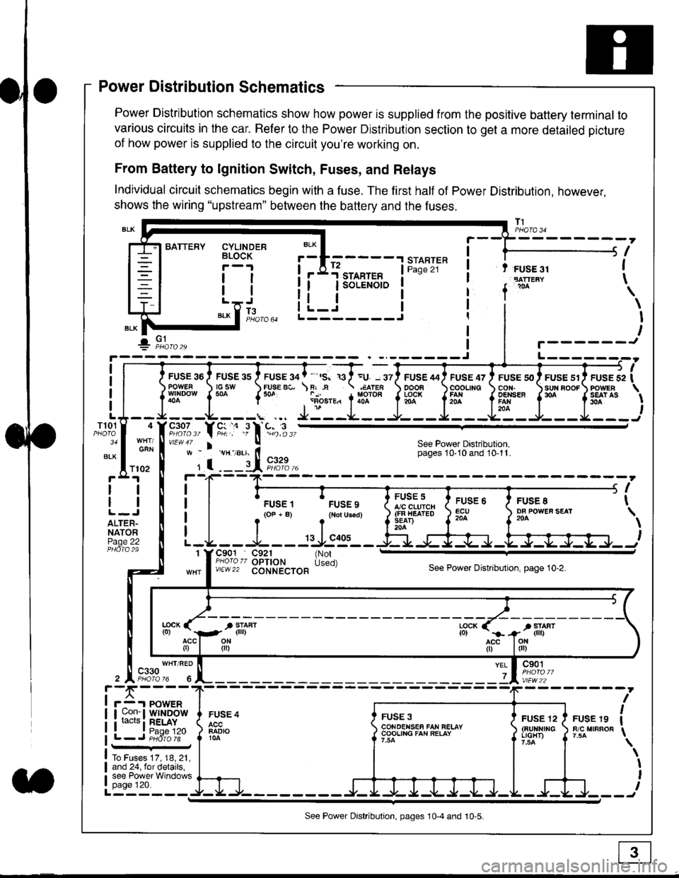
Power Distribution Schematics
Power Distribution schematics show how power is supplied from the positive battery terminal to
various circuits in the car. Refer to the Power Distribution section to get a more detailed picture
of how power is supplied to the circuit you're working on.
From Battery to lgnition Switch, Fuses, and Relays
Individual circuit schematics begin with a fuse. The first half of Power Distribution, however,
shows the wiring "upstream" between the battery and the fuses.
CYLINDERBLOCK
tl
tlL.lt J
",-* f ]fo,o
i BATTERY
IIII
-
----------------Y-?-
ruse so I ruse as I ruse ga | ' ,s. ,a I =u. - srl ruse aai ruse qr I ruse so I ruse sr i ruse iapowEF csw FUsE Bc, \F,.n .;,cren ooon \coounc cor,r. \sun noor powrnw'NDowf50a {* .i1-;.*"1liT""fi3f* f5# fffi'*"f'* fS?'*
- - -L - - -. ... Ji - -.J.- - - -e- - -l. - - -La - J- - - I - - -
"";%,, Y rtr,' .9 l' -%,t",,vtEw47 I ! See Power Dastribution,w - vH-,alr. lt - pages 10,10and 10-11.
' I ---il 9,1?-l--4F--?-
i I
t.urr, 'rrr.,
t i!?'.,,?"" t::=. l ty::.1----.-
-
i
a I r(op-B) .{Noru3€d) J$ifl#ii Jtocl }3fo**."".o'
t -L - - -L - - -: rJ:e'- - -Ei s+s-r -.Fl-J-Jrr.-.
It-STARTER | !Pase 21 ! t FUSE 31I "rn*i
I f
*
i.Jr;-t
i L_i***'" iL-------J
ilr------!
FUSE /I4 ' FUSE 47 ' FUSE 5{' ' FUSE 51' FUSE 52
rlr
OOOB \COOLING CON. \SUN BOOF FOWER
t3f* f5# fffi*" f'* fs?'*
See Power Dastribution,pages 10'10 and 10-11.
T101
34
ALK
4
GAN
I
I
I
I
I\
\I
I
I
FUSE 8DF POWEF SEAT204
FUSE 6ECU204
FUSE 5A/C CLUICH(FN HEATEDSEAD204
C901 C921 {NotPHoro zz OPTION Used)v/EW22 CONNECTOBSee Power Distnbution, page 10-2.
1
FUSE 4
FADIO104
c901
vlEw22
FUSE 12(BUltNrrGLIGHT)
FUSE 19R/C MIRROF
YEL
7
i-f,r-- 't PowERI uon- I Wlt{DOWi racrs i RELAY. t P^da 1tL-J P;dr1ii-
FUSE 3CONOENSEF FAN RELAYCOOLING FAN RELAY
To Fuses 17, 18, 21,and 24, for details,see Power Windowspage 120.a
ll
ll
ALTER-NATORPage 22
f102
c330
See Power Distribution, pages 10-4 and 10-5.
Page 1839 of 2189
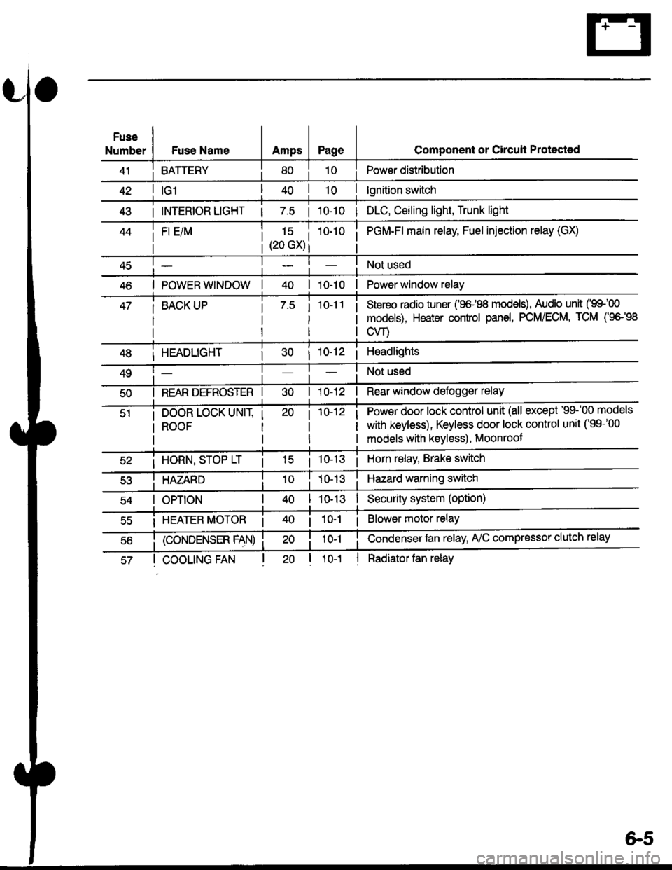
Fuse
NumberFuse NameAmpsPage
BATTERY
Component or Circult Protected
Power distribution
lgnition switch
INTERIOR LIGHT | 7.5 | 10-10 | DLC, Ceiling light, Trunk light
FI E/M15 i(20 GX) i
i PGM-FI main relay, Fuel injection relay (GX)
Not used
POWER WINDOW| 10-10 | Power window relay
BACK UPStereo radio iuner ('9G'98 mod€ls), Audio unit ('99100
models), Heater control panel, PCM/ECM, TCM (9e'98
cvr)
HEADLIGHT
REAR DEFROSTER I
DOOR LOCK UNIT,
ROOF
i 10-12i Headlights
Not used
Rear window defogger relay
Power door lock control unit (all except '99-'00 models
with keyless), Keyless door lock control unit ('99-'00
models with keyless), Moonroof
i HORN, SrOP Lri 10-13i Horn relay, Brake switch
HAZARDHazard warning switch
OPTIONI 10-13I Security system (option)
i HEATER MOTOR Ii 10-1 i Blower motor relay
(CONDENSER FAN)
COOLING FANl1o-1
Condenser Jan relay, A'lC compressor clutch relay
Radiator tan relay
&5
Page 1840 of 2189

Ground-to-Components I ndex
f.,lONOTE: All ground wires are BLK unless otherwise noted.
GroundPageComponents or Circuit Grounded
Battery (BLKYEL)
Steering pump bracket
t+-rg ITransmission housing
l
G101
(-1)
G101
(-2)
14-2
and
14-3
ano
14-1
Powertrain or engine control module (PG1 and pG2 are BLK: LG1 and LG2 are
BRN/BLK), EGR control solenoid valve (CW, EGR valve and lift sensor (Dt6yS enginewith M,/T), Engine coolant temperature switch, pGM-Fl main relay, power steeringpressure switch (USA), Primary HO2S (D16Y5 engine with l\/,/T), Vehicle speed sensor,VTEC pressure switch (D16Y5/D16Y8 engines), CKF sensor (BRN/BLK), Transmission
control module (CYf) (Pc1 is BLK: LG1 is BRN/BLK)
Shielding betvveen the PCM or ECM and these components (all have BRN/BLK wires):
CKF sensor, TDC/CKP/CYP sensor. Primary and secondary heated oxygen sensors.
Knock sensor (CWDl6YB engine), Mainshaft speed sensor (AiT except CVT),
I Countershaft speed sensor (A/T except CVf)
Shielding between the TCM and these components (CVT) (all have BRN/BLK wires):
Drive pulley speed sensor, Driven pulley speed sensor, Secondary gear shaft
speed sensor
Powertrain or engine control module (PG1 and pG2 are BLK; LG1 and LGz are
BRN/BLK), EGR control solenoid valve (D16Y5 engine), EGR valve (Dt685), Engine
coolant temperature switch, Fuel pressure regulator shut-off solenoid valve (D1685),
PGM-FI main relay, Power steering pressure switch (USA), Vehicle speed sensor, VTECpressure switch (All except D16Y7 engine), CKF sensor (A
except 81642) (BRN/BLK)
Shielding between the PCM or ECM and these components (all have BRN/BLK wires):
CKF sensor, TDC/CKP/CYP sensor, Primary and secondary heated oxygen sensors,
Knock sensor (All except D16Y7 engine), i/ainshaft speed sensor (Arf except CW),
Countershaft speed sensor (A,/T except CVf), Drive pulley speed sensor (CW), Drivenpulley speed sensor (CVT), Secondary gear shaft speed sensor (CVf)
I Badiator fan motor, Right front parking/turn signat tight, Right headtight
G20214-4I Cruise control actuator, Left front parking/turn signal lights, Left headlight, Rear window
I washer motor, Windshield washer motor, Washer fluid level switch (,99-'00 Canada)
G401| +-o
and
14-7
Accessory power socket, Brake fluid level switch, Clutch interlock switch (M/T), Clutchswitch (lillT with cruise/D16Y5 engine with MfD, Combination wiper switch (Z wires),
Cruise control main switch, Cruise control unit, Dash lights brightness controller, Data
link connector, Daytime running lights control unit (Canada), Gauge assembly, Horn('96-'97 models), Integrated control unit, Interlock control unit (ArI), Keyless door lock
control unit ('99-'00 models with keyless), Moonroof close and open relays, Moonroof
switch, Park pin switch (A/r), Power window relay, Rear window defogger relay, Rear
window defogger switch ('96-'98 models), Steering lock, Stereo radio tuner (,96-,98
USA: LX, EX, and HX), Turn signal/hazard relay, Windshield wiper motor.....plus
everything grounded through G402
6-6
Page 1859 of 2189
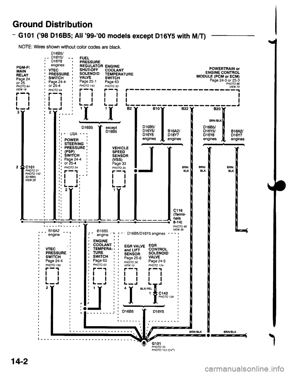
Ground Distribution
- Gl01 ('98 Dl685;All '99-'00 models except D16YS with M/T)
NOTE: Wires shown without color codes are black.
01685/_ D16Y5/ -.016Y8engrnes
.__-;,#'-_,--', engrne ;
, wEc: PRESSURE '
, swtTcH :I Page24-4 iI PHOTO 150: r -'l
:t | :
:l | :,L-J.
FUELPRESSUREREGULATOR ENGINESHUT.OFF COOLANTSOLENOID TEMPERATUREVALVE SWTTCHPage 25-1 Page 63PHOIO 143 PHOTA 33r-1F-.|
llll
lltlL-J L-J
POWERTRAIN olENGINE CONTROLMODULE (PCM or ECM)Page 24-3 ot 25-3PHOTO 86
----:y4
tl
tl
PGi,|.FIMAINRELAYPage 24ol 25
vlEw 18
tl
tl
3Y'I'I
excaptD1685
VEHICLESPEEDSENSOR(vss)Page 336FN/ELKERll/EIKcl01PHOTO 21PHOTO 142(o1685)vtEw 28
ct16Cferml-nals8n 4)
FltaFt( vttw 39t- .''iiti ' " D1685/D16Y5 engrnes ---'
t2
. ENGINE : :
i 933'?il-; i 5"T,Yf,*' 33i,"o, i
i lgfft" i I S.ir1".l^ soL€NorD :' Pase 63 : : ;;;;; - pase 24.i :' PHOTO 63 | | VtEWlO pHOIa124 ;, r-1 | , F-.t r-.r
:l | ;:l | ! | :;t | :,t | | | ;
j,f
ii T.__.,|,,,,,.
j
--
----- --l i otoas I Dr6y5 :
:------.1.--------.
14-2
o-----J