Page 811 of 2189

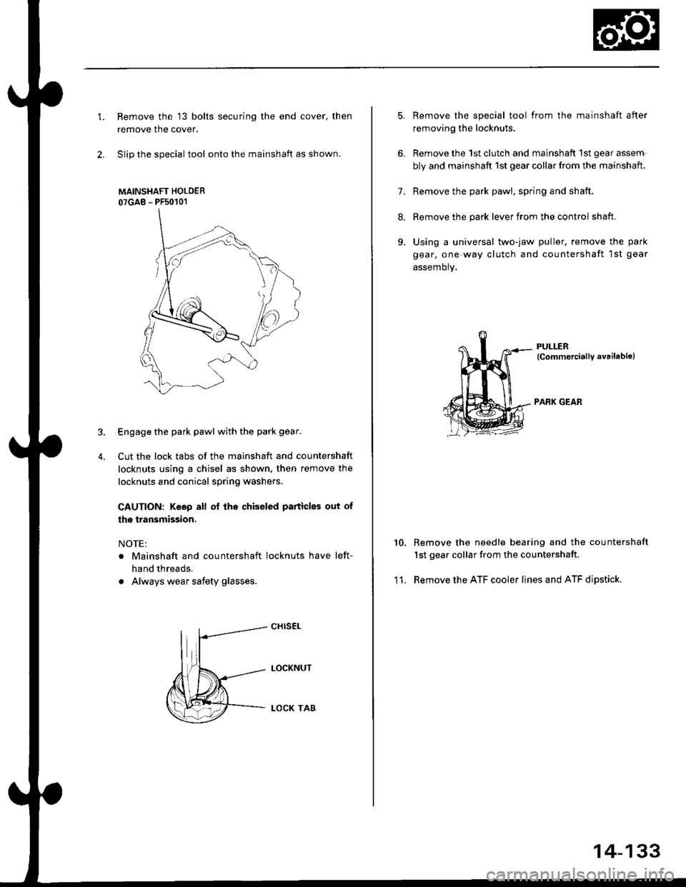
1.Remove the 13 bolts securing the end cover, then
remove the cover.
Slip the special tool onto the mainshaft as shown.
MAINSHAFT HOLOER
07GAB - PFs0101
Engage the park pawl with the park gear.
Cut the lock tabs of the mainshaft and countershaft
locknuts using a chisel as shown. then remove the
locknuts and conical spring washers
CAUTION: Keep all of lhe chiseled particles out of
the transmission.
NOTE:
. Mainshaft and countershaft locknuts have left-
hand threads.
. Always wear safety glasses.
4.
cHrs€L
LOCKNUT
LOCK TA8
5.
6.
11.
Remove the special tool from the mainshaft after
removing the locknuts.
Remove the 1st clutch and mainshaft 1st gear assem
bly and mainshaft 1st gear collar from the mainshaft.
7. Remove the park pawl. spring and shaft.
8. Remove the park lever from the control shaft.
9. Using a universal two-jaw puller, remove the park
gear, one way clutch and countershaft 1st gear
assemory.
PULLER(CommerciallY available)
PARK GEAR
10.Remove the needle bearing and the countershaft
1st gear collar from the countershaft
Remove the ATF cooler lines and ATF dipstick.
14-133
Page 814 of 2189
Torque Converter Housing/Valve Body
Removal
ATF FEEO PIP€
LOCK-UP VALVEBODY
PIN
6x1.0mm
LOCK-UP SEPARATORPLATE
REGULATORVALVE SODY
DOWEL PIN
COOLER RELIEF VAL
SERVO DETENTSTRAINER
SERVO EODY
SEPARATON
BASE
ATF FEEDPIPES
CONTROLSHAFT
DETENTARM SHAFT
DETENTARM
ATF FEED PIPE
6x1.0mm5 Eolts6x1.0mm3 Eolts
MAIN VALBODY
ATF PUMP
DRIVEN
VALVE BODY
PINGEAR SHAFT
ATF PUMP
MAIN SEPARAPLATE
SECONDARYSEPARATOR PLATE
NOTE: The illustration shows the '96 - 98 models, the '99 - 00 models do not have the servo detent base; the servo detentis integral with the servo body.
L
14-136
Page 823 of 2189

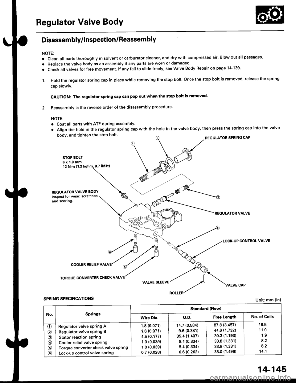
Regulator Valve Body
Disassembly/lnspection/Reassembly
NOTE:
. cleanall parts thoroughly in solvent or carburetor cleaner, and drywith compressed air. Blowoutall passages
. Replace the valve body as an assembly if any parts are worn or damaged.
. check allvalves for free movement. lf anyfail toslidetreely, see valve Body Repairon page 1+139.
1. Hold the regulator spring cap in place while removing the stop bolt. once the stop bolt is removed. release the spring
cap slowly.
CAUTION: The regulator 3pring cap can pop out when the stop boh is removod'
2. Reassembly is the reverse order ofths disassembly procedure.
NOTE:
o Coat all parts with ATF during assembly.
. Align the hole in the regulator spring cap with the hole in the valve body, then press the spring cap into the valve
body, and tighten the stop bolt.
STOP BOLT6x1.0mm12 N.m 11.28.7 tbf.lrl
^/^'ou*'oRsPRrNGcAP
*N@
REGULATOR VALVE
\=f -.-*
*fi /F { a-tLocK.uPcoNrRoLvALVE
cooLERRELlEFvALVr"r?
ry
roRouE coNvERrER cHEcKv ^LvE//
v ^r* "r**::f vi{LvE cAp
SPRING SPECIFICANONS
REGULATOR VALVE BODY
Inspect lor wear, scratches
and scorlng.
Unit: mm (in)
No,Springe
Standard (Now)
Wire Dia.o.D.Free LengrthNo. of Coils
o
o
@
@
@
Regulator valve sPring A
Regulator valve spring B
Stator reaction spring
Cooler relief valve spring
Torque converter check valve spring
Lock-up control valve sPring
1.8 {0.07'�r)
1.8 (0.071)
4.5 (0.177)
1.0 (0.039)
1.0 (0.039)
0.7 (0.028)
'r4.7 (0.584)
9.6 (0.381)
35.4 (1.407)
8.4 {0.334)
8.4 {0.334}
6.6 {0.262}
87.8 (3.457)
44.0 (1.732)
30.3 (1.193)
33.8 (1.331)
33.811.3311
38.0 {1.4961
11.0
1.9
8.2
a.2't 4.1
14-145
Page 855 of 2189

1.Install the ATF magnet and suction pipe collar in the
torque converter housing. if necessary.
lnstall the main seDarator plate and the two dowel
pins on the torque converter housang.
Install the ATF pump drive gear, ATF pump driven
gear and ATF pump driven gear shaft on the torque
converter housing.
NOTE; Install the ATF pump driven gear with its
grooved and chamfered side tacing down.
ATF PUMP
ATF PUMP DRIVENGEAR SHAFT
ATF PUMPDRIVEN GEAR
Grooved and chamferedside taces separalorplate.MAIN SEPARATORPLATE
4.Loosely install the main valve body with five bolts.
Make sure the ATF pump drive gear rotates smoothly
in the normal operating direction and the ATF pump
driven gear shaft moves smoothly in the axial and
normal operating directions.
Install the secondary valve body, separator plate
and two dowel pins on the main valve body.
NOTE: Do not installthe bolts.
6. Install the control shaft in the housing with the con-
trol shaft and manual valve together.
7. lnstall the detent arm and arm shaft in the main
valve body, then hook the detent arm spring to the
detent arm,
SERVO SEPARATOR PLATE
DETENT
MANUAL VALVE
DETENT ARM SPRING
15.
14-177
a
10.
11.
Install the servo body and separator plate on the
secondary valve body ('95 - 98 models: seven bolts.'99 - 00 models: eight boltsl.
For '96 - 98 models: Install the servo detent base
and the ATF strainer (two boltsl.
For'99 - 00 models: Install the ATF strainer (one
bolt).
Tighten the five bolts on the main valve body to 12
N.m ('1.2 kgf.m,8.7 lbf.ft).
Make sure the ATF pump drive gear and ATF pump
driven gear shaft move smoothlY'
lf the ATF pump drive gsar and ATF pump driven
gear shaft do not move freely, loosen ths five bolts
on the main valve body, and disassemble the valve
bodies.
Realign the ATF pump driven gear shaft and reassem-
ble the valve bodies, then retighten the bolts to the
specified torque,
CAUTION: Fsilule to align tho ATF pump driven
goar shaft corr.ctly will rscuh in a s€ized ATF pump
drive goar or ATF pump d ven gear shaft.
Install the stator shaft and stop shaft.
Install the bolts and the shaft stop on the secondary
valve body, then tighten the bolts (three boltsl.
Install the torque converter check valve, cooler relief
valve and valve springs in the regulator valve body.
then install the regulator valve body on the main
valve bodv (one bolt).
Install the lock-up valve body on the regulator valve
bodv (seven bolts).
Install the ATF feed pipes in the main valve bodY,
the three ATF feed pipes in the secondary valve and
the four ATF feed pipes in the servo body. (cont'dl
12.
't 3.
14.
PUMP
Page 859 of 2189
36. Remove the special tool from mainshaft, then stake
each locknut using a 3.5 mm punch as shown'
COUNTERSHAFTLOCKNUT
Set the park lever in the El position, then verify that
the park Pawl engages the Park gear
lf the Dawl does not engage fully, check the park
pawl stop clearance (see page 14-175).
Tighten the lock boll and bend the lock tab'
10 tbl.ftl
a'f
38.
ao
LOCKWASHEF
0.7 - 1.2 mm(0.03 - 0.05 in)
Erl.Omm14 t{.m (1.4 kgf'm,
\.- (o)
40. Instsllthe end cover with two dowel pinsandanew
gasket (thirteen bolts)'
TOROUE: 12 N'm (1.2 tgf'm. 8.7 lbf'ft}
END COVER
lnstall the ATF cooler lines with new sealing wash-
9rs.
TOROUE: 28 N.m {2.9 kgf'm. 21 lbt'ft1
Install the ATF diPstick.
41.
14-181
Page 861 of 2189

Transmission
1.
lnstallation
Flush the ATF cooler as described on page l4-187
and 14-188.
Install the torque converter assembly securely with
a new O-ring on the mainshaft
STARTER MOTOR
14 mm DOWEL PIN
TOROUE O-RING
CONVERTER Replace
lnstall the starter motor on
housing, then install the two
the torque converter housing.
lil mm DOWEL PIN
the torque converter
14 mm dowsl pins in
MOUNTINGBRACKET
Place the transmission on a jack, and raise it to the
engine assembly level.
Attach the transmission to the engine, then install
two transmission housing mounting bolts and two
rear engine mounting bolts.REAR ENGINEMOUNNNG BOLTS1,1r15mm&| N.m 18.5 kgf m, 61 lbf'ft]
Replace.
64 N.m {6.547 tbf frlWASHER
ENGINE
TRANSMISSION HOUSINGMOUNTING BOLTS12 x 1.25 mm
45 N.m {4.5 kgf.m,
JACK
6. Install the transmission mount bracket.
12 x 1.25 mm6il N.m {6.5 kgf.m, a7 lbf'ft)
12 x 1.25 mm74 N.m (7.5 kgf.m,54 tbt.fr)
TRANSMISSION MOUNT
7.Install the remaining transmission housing mount-
ing bolts and remaining rear engine mounting bolt.
REAR ENGINEMOUNTING BOLT14 x 1.5 mmel N.m (8.5 kgt'm,61 tbl.ft)Replace.
HOUSING
MOUNTING BOLTS12 x 1.25 mmg N m (6.5 kgf m, 'l? lblftl
8. Remove the transmission jack.
(cont'd)
14-183
Page 862 of 2189

Transmission
Installation (cont'dl
9. Attach the torque converter to the drive plate witheight drive plate bolts and torque as follows:Rotate the crankshaft pulley as necessary to tightenthe bolts to 1/2 of the specified torque. then to thefinal torque, in a crisscross pattern.
After tightening the last bolt, check that the crank-shaft rotates freely.
TOROUE: 12 N.m {1.2 kgl.m, 8.7 tbt{r}
10 x 1.25 mm
6x1.0mm12 N.m (1.2 kgt m,8.7 rbt ft)
I 1.25 mm2/t N.m {2.4 kg{.m,17 tbt ftlCONVERTEB
10. Install the torque convener cover and the €nginestiffener.'11. Tighten the crsnkshaft pull€y bolt, if necessary (see
section 61.
12. Connect the ATF cooler hoses to the ATF cooler lines(see page 1,t192).
ATF COOIIRUNE
10 x 1.25 mma,l N.m {4.5 kgl.m,33 rbt.fttRIGHT FRONT 12 x 1.25 mmMOUNT/BRACKET 6.t N.m (6.5 kg{.m,47 tbt ftl
13. Install the right front mounvbracket.
4,r N.m 14.5 kgf.m,33 lbtft)
COVER
L,
14-1A4
SHIFT CABLE
SHIFT CAAE COVER
14. Install the control lever with a new lock washer tothe control shaft, then install the shift cable cover.
CAUION: Taks care not to bend the shift cable.
L(rcK WASHERReplace.
8 x 1,25 r'|m22N-m12.2 tgt m. 16lbnftl
x 1.0 mmtit N.m 11.4 kgt m,10 tbr,ft,
15. lnstall the exhaust pipe A.
NOTE: D16Y8 engine is shown; D16y/ engine is sim_ilar.
Replace.
GASKETReplace.
SELF.LOCKING NUTReplace.10 x 1.25 mm54 N.m (5.5 lgf.m,40 tbt ftl
NUTSELF.LOCKING NUTReplace.8 x 1.25 mm22 N.m {2.2 kgl.m, 16lbtfrl
Replace.8 x 1.25 mm16 N.m {1.6 kgI.m,12 tbf.ft)
Page 864 of 2189

Transmission
Installation {cont'd)
Connect the lock-up control solenoid connector. andinstall the transmission ground cable.
6 x '1.0 mm12 N.m {1.2 kgf.m, 8.7 lbl.ft}
LOCK.UP CONTROLSOLENOID CONNECTOR
Connect the staner cables on the staner motor. andinstall the cable holder.
NOTE; When installing the starter cable terminal.make sure that the crimped side of the ring terminalis facing out (see section 23).
6x1.0mm12 N.m 11.2 kg{.m.8.7 tbtftl
{0.9 kg'f.m, 7 lbf.ftl
TRANSMISSIONGROUND CABLE
b
14-186
STARTER CAELE
24. Installthe intake air duct.
D16Y7 engine:
Install the intake air duct and the resonaror.
D16Y8 engine:
lnstall the intake air duct and the air cleaner hous_ang assembly.
25. Refill the transmission with ATF (see page 14_1.18).
26. Connect the positive (+) cable first. then the nega-tive (-) cable to the battery.
27. Check the ignition timing (see section 23).
28. Start the engine. Set the parking brake, and shift thetransmission through all gears. three times. Checkthe shift cable adjustment (see page 14_190).
29, Check the front wheel alignment (see section 1g).
30. Let the engine reach operating temperature (thecooling fan comes on) with the transmission in Nor @ position, then turn it off and check the fluidlevel (see page 14- 7).
31. Road test as described on pages 14-113 thru ,14_116.