1998 DODGE RAM 1500 ECU
[x] Cancel search: ECUPage 1414 of 2627
(6) Remove the viscous fan/drive (Refer to 7 -
COOLING/ENGINE/RADIATOR FAN - REMOVAL).
(7) Remove radiator (Refer to 7 - COOLING/EN-
GINE/RADIATOR - REMOVAL).
(8) Remove the upper crossmember and top core
support.
NOTE: It is not necessary to drain A/C system for
engine removal.
(9) Remove the A/C compressor with the lines
attached. Secure compressor out of the way.
(10) Remove generator assembly (Refer to 8 -
ELECTRICAL/CHARGING/GENERATOR -
REMOVAL).
(11) Remove the intake manifold and IAFM as an
assembly(Refer to 9 - ENGINE/MANIFOLDS/IN-
TAKE MANIFOLD - REMOVAL).
(12) Disconnect the heater hoses.
NOTE: It is not necessary to disconnect P/S hoses
from pump, for P/S pump removal.
(13) Remove the power steering pump and set
aside.
(14) Disconnect the fuel supply line (Refer to 14 -
FUEL SYSTEM/FUEL DELIVERY/QUICK CON-
NECT FITTING - STANDARD PROCEDURE).
(15) Raise and support the vehicle on a hoist and
drain the engine oil.
(16) Remove engine front mount thru-bolt nuts.
(17) Remove right side axle retaining bolts.
(18) Disconnect the transmission oil cooler lines
from their retainers at the oil pan bolts.
(19) Disconnect exhaust pipe at manifolds.
(20) Disconnect the starter wires. Remove starter
motor (Refer to 8 - ELECTRICAL/STARTING/
STARTER MOTOR - REMOVAL).
(21) Remove the structural dust cover and trans-
mission inspection cover,(Refer to 9 - ENGINE/EN-
GINE BLOCK/STRUCTURAL COVER - REMOVAL).
(22) Remove drive plate to converter bolts (Auto-
matic transmission equipped vehicles).
(23) Remove transmission bell housing to engine
block bolts.
(24) Lower the vehicle.
(25) Install engine lift fixture, special tool # 8984.
(26) Separate engine from transmission, remove
engine from vehicle, and install engine assembly on a
repair stand.
INSTALLATION
(1) Install engine lift fixture Special tool # 8984.
(2) Position the engine in the engine compartment.
(3) Lower engine into compartment and align
engine with transmission:²Manual Transmission: Align clutch disc assem-
bly (if disturbed). Install transmission input shaft
into clutch disc while mating engine and transmis-
sion surfaces. Install two transmission to engine
block mounting bolts finger tight.
²Automatic Transmission: Mate engine and trans-
mission and install two transmission to engine block
mounting bolts finger tight.
(4) Position the thru-bolt into the support cushion
brackets.
(5) Lower engine assembly until engine mount
through bolts rest in mount perches.
(6) Install remaining transmission to engine block
mounting bolts and tighten.
(7) Tighten engine mount through bolts.
(8) Install drive plate to torque converter bolts.
(Automatic transmission models)
(9) Install the structural dust cover and transmis-
sion dust cover,(Refer to 9 - ENGINE/ENGINE
BLOCK/STRUCTURAL COVER - INSTALLATION).
(10) Install the starter and connect the starter
wires (Refer to 8 - ELECTRICAL/STARTING/
STARTER MOTOR - INSTALLATION).
(11) Install exhaust pipe to manifold.
(12) Lower the vehicle.
(13) Remove engine lift fixture, special tool # 8984.
(14) Connect the fuel supply line (Refer to 14 -
FUEL SYSTEM/FUEL DELIVERY/QUICK CON-
NECT FITTING - STANDARD PROCEDURE).
(15) Reinstall the power steering pump.
(16) Connect the heater hoses.
(17) Install the intake manifold.
(18) Using a new gasket, install throttle body
(Refer to 14 - FUEL SYSTEM/FUEL INJECTION/
THROTTLE BODY - INSTALLATION).
(19) Install the generator and wire connections
(Refer to 8 - ELECTRICAL/CHARGING/GENERA-
TOR - INSTALLATION).
(20) Install a/c compressor and lines (Refer to 24 -
HEATING & AIR CONDITIONING/PLUMBING/A/C
COMPRESSOR - INSTALLATION).
(21) Install the accessory drive belt (Refer to 7 -
COOLING/ACCESSORY DRIVE/DRIVE BELTS -
INSTALLATION).
(22) Install upper radiator support crossmember.
(23) Install radiator (Refer to 7 - COOLING/EN-
GINE/RADIATOR - INSTALLATION).
(24) Connect the radiator lower hose.
(25) Connect the transmission oil cooler lines to
the radiator.
(26) Install the fan shroud.
(27) Install the fan (Refer to 7 - COOLING/EN-
GINE/RADIATOR FAN - INSTALLATION).
(28) Connect the radiator upper hose.
(29) Install the washer bottle.
(30) Connect the transmission cooler lines.
DRENGINE - 5.7L 9 - 191
ENGINE - 5.7L (Continued)
Page 1463 of 2627
material to cure. This material is available in three
ounce tubes and has a shelf life of one year. After one
year this material will not properly cure. Always
inspect the package for the expiration date before
use.
MOPARtATF RTV
MopartATF RTV is a specifically designed black
silicone rubber RTV that retains adhesion and seal-
ing properties to seal components exposed to auto-
matic transmission fluid, engine coolants, and
moisture. This material is available in three ounce
tubes and has a shelf life of one year. After one year
this material will not properly cure. Always inspect
the package for the expiration date before use.
MOPARtGASKET MAKER
MopartGasket Maker is an anaerobic type gasket
material. The material cures in the absence of air
when squeezed between two metallic surfaces. It will
not cure if left in the uncovered tube. The anaerobic
material is for use between two machined surfaces.
Do not use on flexible metal flanges.
MOPARtGASKET SEALANT
MopartGasket Sealant is a slow drying, perma-
nently soft sealer. This material is recommended for
sealing threaded fittings and gaskets against leakage
of oil and coolant. Can be used on threaded and
machined parts under all temperatures. This mate-
rial is used on engines with multi-layer steel (MLS)
cylinder head gaskets. This material also will pre-
vent corrosion. MopartGasket Sealant is available in
a 13 oz. aerosol can or 4oz./16 oz. can w/applicator.
FORM-IN-PLACE GASKET AND SEALER
APPLICATION
Assembling parts using a form-in-place gasket
requires care but it's easier than using precut gas-
kets.
MopartGasket Maker material should be applied
sparingly 1 mm (0.040 in.) diameter or less of sealant
to one gasket surface. Be certain the material sur-
rounds each mounting hole. Excess material can eas-
ily be wiped off. Components should be torqued in
place within 15 minutes. The use of a locating dowel
is recommended during assembly to prevent smear-
ing material off the location.
MopartEngine RTV GEN II or ATF RTV gasket
material should be applied in a continuous bead
approximately 3 mm (0.120 in.) in diameter. All
mounting holes must be circled. For corner sealing, a
3.17 or 6.35 mm (1/8 or 1/4 in.) drop is placed in the
center of the gasket contact area. Uncured sealant
may be removed with a shop towel. Components
should be torqued in place while the sealant is still
wet to the touch (within 10 minutes). The usage of a
locating dowel is recommended during assembly to
prevent smearing material off the location.MopartGasket Sealant in an aerosol can should be
applied using a thin, even coat sprayed completely
over both surfaces to be joined, and both sides of a
gasket. Then proceed with assembly. Material in a
can w/applicator can be brushed on evenly over the
sealing surfaces. Material in an aerosol can should be
used on engines with multi-layer steel gaskets.
STANDARD PROCEDURE - REPAIR DAMAGED
OR WORN THREADS
CAUTION: Be sure that the tapped holes maintain
the original center line.
Damaged or worn threads can be repaired. Essen-
tially, this repair consists of:
²Drilling out worn or damaged threads.
²Tapping the hole with a special Heli-Coil Tap, or
equivalent.
²Installing an insert into the tapped hole to bring
the hole back to its original thread size.
STANDARD PROCEDUREÐHYDROSTATIC
LOCK
CAUTION: DO NOT use the starter motor to rotate
the crankshaft. Severe damage could occur.
When an engine is suspected of hydrostatic lock
(regardless of what caused the problem), follow the
steps below.
(1) Disconnect the negative cable(s) from the bat-
tery.
(2) Inspect air cleaner, induction system, and
intake manifold to ensure system is dry and clear of
foreign material.
(3) Place a shop towel around the fuel injectors to
catch any fluid that may possibly be under pressure
in the cylinder head. Remove the fuel injectors (Refer
to 14 - FUEL SYSTEM/FUEL INJECTION/FUEL
INJECTOR - REMOVAL).
(4) With all injectors removed, rotate the crank-
shaft using the crankshaft barring tool (PN 7471±B).
(5) Identify the fluid in the cylinders (coolant, fuel,
oil, etc.).
(6) Be sure all fluid has been removed from the
cylinders.
(7) Repair engine or components as necessary to
prevent this problem from occurring again.
(8) Squirt a small amount of engine oil into the
cylinders to lubricate the walls. This will prevent
damage on restart.
(9) Install fuel injectors (Refer to 14 - FUEL SYS-
TEM/FUEL INJECTION/FUEL INJECTOR -
INSTALLATION).
9 - 240 ENGINE 5.9L DIESELDR
ENGINE 5.9L DIESEL (Continued)
Page 1472 of 2627
Filter Removal
(1) The housing cover is equipped with spring clips
(Fig. 6) and is hinged with plastic tabs. Unlatch clips
from top of air cleaner housing and tilt housing cover
up for cover removal.
(2) Remove air cleaner element from air cleaner
housing.
INSTALLATION
(1) Before installing new air cleaner element (fil-
ter), clean inside of air cleaner housing.
(2) Position air cleaner cover to tabs on front of air
cleaner housing. Latch spring clips to seal cover to
housing.
CYLINDER HEAD
DESCRIPTION
The cylinder head is constructed of cast iron and is
a one piece cross flow design with four valves per cyl-
inder. The arrangement of two intake and two
exhaust valves per cylinder allows for a centrally
located injector. The cylinder head also includes an
integral intake manifold, an integral thermostat
housing, and a longitudal fuel return rifle, which
exits at the rear of the head. The 24 valve design
also includes integrally cast valve guides and hard-
ened intake and exhaust valve seat inserts.
REMOVAL
(1) Disconnect battery negative cables.
(2) Raise vehicle on hoist.
(3) Drain engine coolant.
(4) Disconnect exhaust pipe from turbocharger
elbow.
(5) Disconnect turbocharger oil drain tube at rub-
ber hose connection. Cap off open ports to prevent
intrusion of dirt or foreign material.
(6) Lower vehicle.
(7) Disconnect air inlet temperature/pressure sen-
sor.
(8) Remove air cleaner housing and snorkel from
the vehicle. Cap off turbocharger air inlet to prevent
intrusion of dirt or foreign material.
(9) Disconnect cab heater core supply and return
hoses from the cylinder head and heater pipe.
(10) Disconnect turbocharger oil supply line at the
turbocharger end. Cap off open ports to prevent
intrusion of dirt or foreign material.
(11) Remove exhaust manifold-to-cylinder head
bolts, spacers, heat shield, retention straps, and cab
heater plumbing. Remove exhaust manifold and tur-
bocharger from the vehicle as an assembly.
(12) Remove cooling fan assembly.
(13) Remove accessory drive belt (Refer to 7 -
COOLING/ACCESSORY DRIVE/DRIVE BELTS -
REMOVAL).
(14) Remove cooling fan support from cylinder
block.
(15) Remove upper generator bolt, loosen lower
generator bolt, and rotate generator away from cylin-
der head.
(16) Disconnect radiator upper hose from the ther-
mostat housing.
(17) Disconnect the Intake Air Temperature/Mani-
fold Air Pressure, and Coolant Temperature sensor
connectors.
(18) Remove the engine harness to cylinder head
attaching bolts and P-clips at front of head.
(19) Remove the throttle linkage cover (Fig. 8).
(20) For automatic equipped vehicles only, remove
the six (6) accelerator pedal position sensor assem-
bly-to-cylinder head bracket bolts (Fig. 9) and secure
the entire assembly out of the way. Disconnect the
APPS connector (Fig. 10).It is not necessary to
disconnect the cables from the throttle control
assembly.
(21) Remove the intake air grid heater wires from
the grid heater.
(22) Remove engine oil level indicator tube attach-
ing bolt at fuel filter housing bracket and inlet air
connection..
(23) Remove the charge air cooler-to-air inlet hous-
ing pipe.
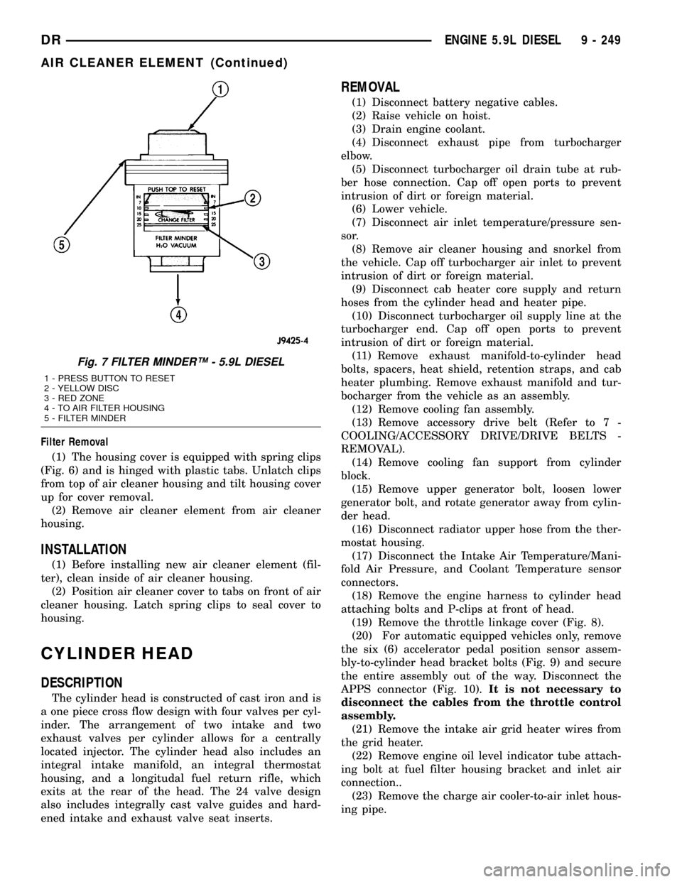
Fig. 7 FILTER MINDERŸ - 5.9L DIESEL
1 - PRESS BUTTON TO RESET
2 - YELLOW DISC
3 - RED ZONE
4 - TO AIR FILTER HOUSING
5 - FILTER MINDER
DRENGINE 5.9L DIESEL 9 - 249
AIR CLEANER ELEMENT (Continued)
Page 1477 of 2627
(9) Install rocker housing and bolts. Tighten to 24
Nm (18 lb. ft.).
(10) Install fuel injector(Refer to 14 - FUEL SYS-
TEM/FUEL INJECTION/FUEL INJECTOR -
INSTALLATION).
(11) Install injector harness nuts. Tighten to 1.25
Nm (11 lb. in.).
(12) Install cylinder head cover (Refer to 9 -
ENGINE/CYLINDER HEAD/CYLINDER HEAD
COVER(S) - INSTALLATION).
(13) Install wire harness P-clip to cylinder head
behind filter housing 24 N´m (18 ft. lbs.).
(14) Connect the IAT/MAP sensor connector.
(15) Install the fuel filter canister assembly and
torque mounting bolts to 24 N´m (18 ft. lbs.).
(16) Connect fuel lift pump, WIF sensor, and fuel
heater.
(17) Remove the engine lift bracket at rear of cyl-
inder head.
CAUTION: Failure to follow procedure will result in
fuel leaks and/or fuel system failure.
(18)Install the fuel rail and high pressure
fuel lines as follows:
(a) Hand tighten fuel rail bolts.
(b) Hand tighten fuel drain line to pressure lim-
iting valve. Hand tighten banjo bolt at fuel filter
housing.
(c) Hand tighten fuel rail-to-cylinder head high
pressure fuel lines.(d) Install fuel line brace bolts-to-intake mani-
fold finger tight.
(e) Hand tighten fuel pump to fuel rail line.
(f) Torque fuel line nuts at cylinder head to 30
Nm ( 22 ft. lbs.).
(g) Torque fuel line nuts at fuel rail to 30 Nm
(22 ft. lbs.)
(h) Using a back up wrench, torque fuel pump to
fuel rail line to 37 Nm (27 ft. lbs.). At injection
pump.
(i) Torque fuel pump to fuel rail line to 37 Nm
(27 ft. lbs.) at fuel rail.
(j) Torque fuel drain banjo bolt at pressure lim-
iting valve and front of fuel filter housing to 24 Nm
(18 ft. lbs.).
(k) Torque fuel line brace bolts to 24 N´m (18 ft.
lbs.).
(l) Torque rail bolts to 24 Nm (18 ft. lbs.).
(m) Connect fuel pressure sensor.
(19) Install the engine lift bracket at the rear of
cylinder head. Torque to 77 N´m (57 ft. lbs.).
(20) Reposition number 6 fuel line shield and
torque to 43 N´m (32 ft. lbs.).
(21) Install the fuel filter to injection pump low
pressure line. Inspect and replace sealing washers if
necessary. Torque banjo bolts to 24 N´m (18 ft. lbs.).
(22) Connect fuel return line at back of cylinder
head hand tight.
(23) Connect fuel return line at filter housing hand
tight.
(24) Torque banjo connections at cylinder head and
fuel filter housing to 24 Nm (18 ft. lbs.)
(25) Install bracket to rear of filter housing.
Torque to 24 Nm (18 ft. lbs.).
(26) Using new gaskets, install the intake grid
heater and air inlet housing. Torque bolts to 24 N´m
(18 ft. lbs.).
(27) Install wire harness P-clip and push on clip to
air inlet housing.
(28) Connect engine oil level indicator tube at fuel
filter housing and at air inlet housing.
(29) Connect the APPS connector.
(30) Install the APPS assembly to the cylinder
head bracket and torque bolts to 24 N´m (18 ft. lbs.).
(31) Install the throttle linkage cover.
(32) Install the charge air cooler-to-air inlet hous-
ing duct assembly. Torque all clamps to 11 N´m (100
in. lbs.).
(33) Connect intake grid heater wires.
(34) Secure engine harness to front of cylinder
head with bolt at four locations.
(35) Connect engine coolant temperature sensor
connector.
(36) Connect radiator upper hose to thermostat
housing.
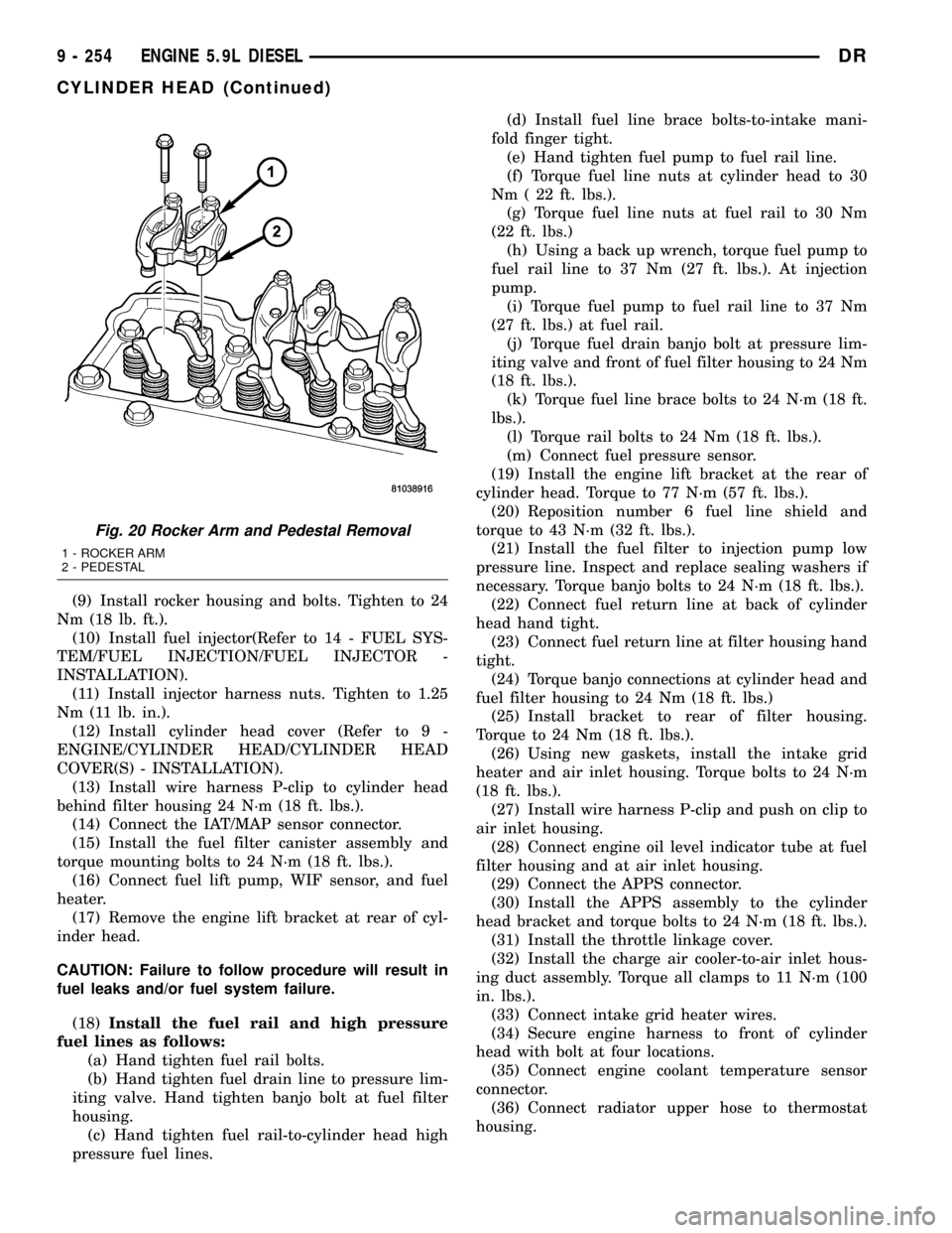
Fig. 20 Rocker Arm and Pedestal Removal
1 - ROCKER ARM
2 - PEDESTAL
9 - 254 ENGINE 5.9L DIESELDR
CYLINDER HEAD (Continued)
Page 1492 of 2627
(15) Remove the two charge air cooler mounting
bolts.
(16) Remove charge air cooler (and A/C condenser
if equipped) from vehicle.
(17) Remove accessory drive belt (Refer to 7 -
COOLING/ACCESSORY DRIVE/DRIVE BELTS -
REMOVAL).
(18) Remove accessory drive belt tensioner.
(19) Remove the fan support/hub assembly.
(20) Remove crankshaft damper and speed indica-
tor ring (Refer to 9 - ENGINE/ENGINE BLOCK/VI-
BRATION DAMPER - REMOVAL).
(21) Remove the gear cover-to-housing bolts and
gently pry the cover away from the housing, taking
care not to mar the sealing surfaces. Remove dust
seal with cover.
(22) Using Special Tool 7471±B Crankshaft Bar-
ring Tool, rotate the crankshaft to align the timing
marks on the crankshaft and the camshaft gears.
(23) Remove the cylinder head cover (Refer to 9 -
ENGINE/CYLINDER HEAD/CYLINDER HEAD
COVER(S) - REMOVAL).
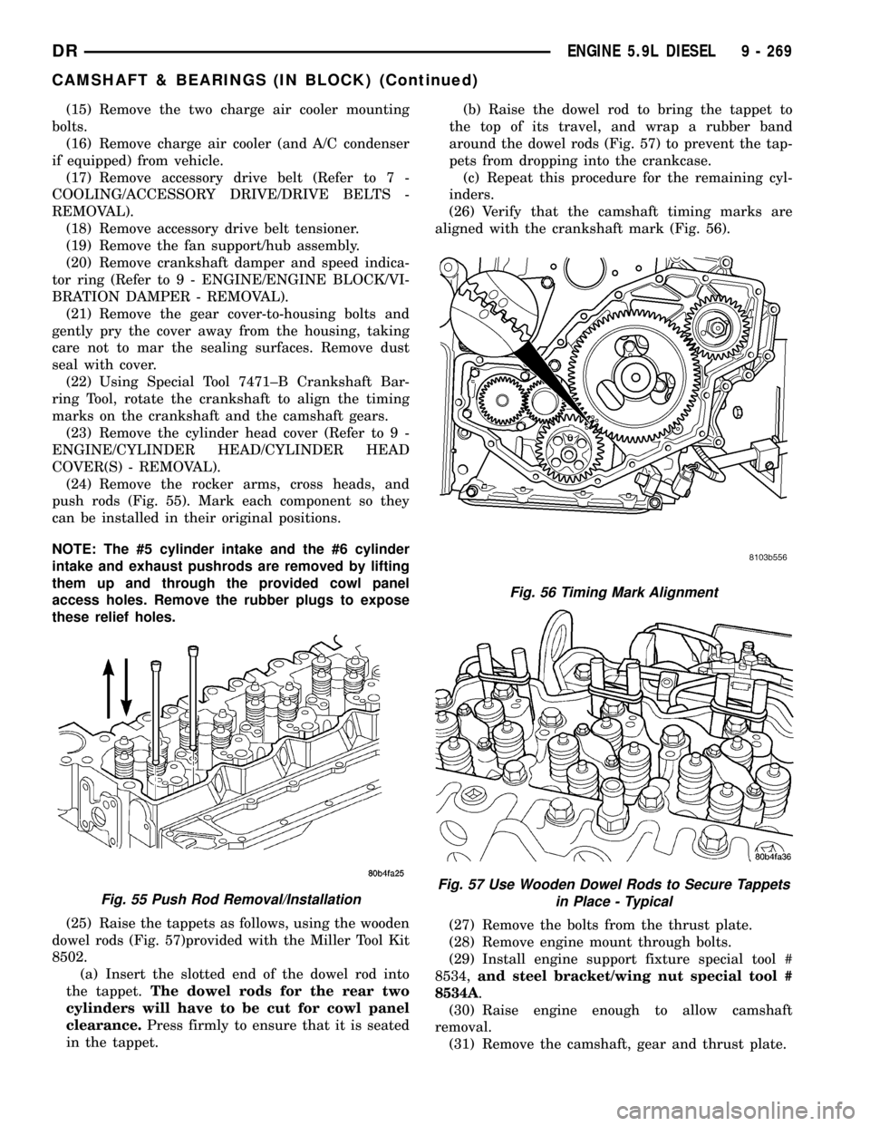
(24) Remove the rocker arms, cross heads, and
push rods (Fig. 55). Mark each component so they
can be installed in their original positions.
NOTE: The #5 cylinder intake and the #6 cylinder
intake and exhaust pushrods are removed by lifting
them up and through the provided cowl panel
access holes. Remove the rubber plugs to expose
these relief holes.
(25) Raise the tappets as follows, using the wooden
dowel rods (Fig. 57)provided with the Miller Tool Kit
8502.
(a) Insert the slotted end of the dowel rod into
the tappet.The dowel rods for the rear two
cylinders will have to be cut for cowl panel
clearance.Press firmly to ensure that it is seated
in the tappet.(b) Raise the dowel rod to bring the tappet to
the top of its travel, and wrap a rubber band
around the dowel rods (Fig. 57) to prevent the tap-
pets from dropping into the crankcase.
(c) Repeat this procedure for the remaining cyl-
inders.
(26) Verify that the camshaft timing marks are
aligned with the crankshaft mark (Fig. 56).
(27) Remove the bolts from the thrust plate.
(28) Remove engine mount through bolts.
(29) Install engine support fixture special tool #
8534,and steel bracket/wing nut special tool #
8534A.
(30) Raise engine enough to allow camshaft
removal.
(31) Remove the camshaft, gear and thrust plate.
Fig. 55 Push Rod Removal/Installation
Fig. 56 Timing Mark Alignment
Fig. 57 Use Wooden Dowel Rods to Secure Tappets
in Place - Typical
DRENGINE 5.9L DIESEL 9 - 269
CAMSHAFT & BEARINGS (IN BLOCK) (Continued)
Page 1502 of 2627
SOLID LIFTERS/TAPPETS
REMOVAL
NOTE: This procedure requires use of Miller Tool
8502 Tappet Replacement Kit.
(1) Remove camshaft (Refer to 9 - ENGINE/EN-
GINE BLOCK/CAMSHAFT & BEARINGS (IN
BLOCK) - REMOVAL).
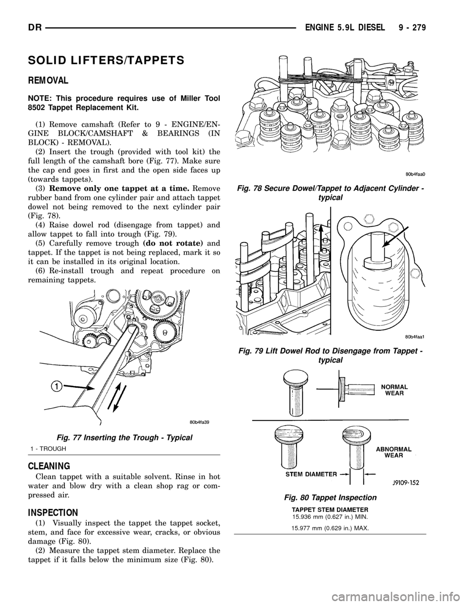
(2) Insert the trough (provided with tool kit) the
full length of the camshaft bore (Fig. 77). Make sure
the cap end goes in first and the open side faces up
(towards tappets).
(3)Remove only one tappet at a time.Remove
rubber band from one cylinder pair and attach tappet
dowel not being removed to the next cylinder pair
(Fig. 78).
(4) Raise dowel rod (disengage from tappet) and
allow tappet to fall into trough (Fig. 79).
(5) Carefully remove trough(do not rotate)and
tappet. If the tappet is not being replaced, mark it so
it can be installed in its original location.
(6) Re-install trough and repeat procedure on
remaining tappets.
CLEANING
Clean tappet with a suitable solvent. Rinse in hot
water and blow dry with a clean shop rag or com-
pressed air.
INSPECTION
(1) Visually inspect the tappet the tappet socket,
stem, and face for excessive wear, cracks, or obvious
damage (Fig. 80).
(2) Measure the tappet stem diameter. Replace the
tappet if it falls below the minimum size (Fig. 80).
Fig. 77 Inserting the Trough - Typical
1 - TROUGH
Fig. 78 Secure Dowel/Tappet to Adjacent Cylinder -
typical
Fig. 79 Lift Dowel Rod to Disengage from Tappet -
typical
Fig. 80 Tappet Inspection
TAPPET STEM DIAMETER
15.936 mm (0.627 in.) MIN.
15.977 mm (0.629 in.) MAX.
DRENGINE 5.9L DIESEL 9 - 279
Page 1503 of 2627
INSTALLATION
(1) Insert the trough the full length of the cam-
shaft bore. Again, make sure the cap end goes in first
and the open side faces up (towards tappets).
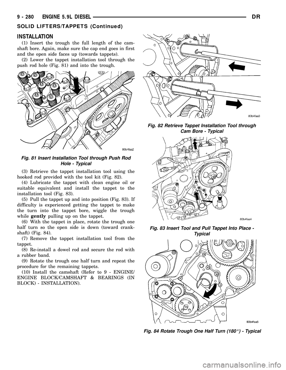
(2) Lower the tappet installation tool through the
push rod hole (Fig. 81) and into the trough.
(3) Retrieve the tappet installation tool using the
hooked rod provided with the tool kit (Fig. 82).
(4) Lubricate the tappet with clean engine oil or
suitable equivalent and install the tappet to the
installation tool (Fig. 83).
(5) Pull the tappet up and into position (Fig. 83). If
difficulty is experienced getting the tappet to make
the turn into the tappet bore, wiggle the trough
whilegentlypulling up on the tappet.
(6) With the tappet in place, rotate the trough one
half turn so the open side is down (toward crank-
shaft) (Fig. 84).
(7) Remove the tappet installation tool from the
tappet.
(8) Re-install a dowel rod and secure the rod with
a rubber band.
(9) Rotate the trough one half turn and repeat the
procedure for the remaining tappets.
(10) Install the camshaft (Refer to 9 - ENGINE/
ENGINE BLOCK/CAMSHAFT & BEARINGS (IN
BLOCK) - INSTALLATION).
Fig. 81 Insert Installation Tool through Push Rod
Hole - Typical
Fig. 82 Retrieve Tappet Installation Tool through
Cam Bore - Typical
Fig. 83 Insert Tool and Pull Tappet Into Place -
Typical
Fig. 84 Rotate Trough One Half Turn (180É) - Typical
9 - 280 ENGINE 5.9L DIESELDR
SOLID LIFTERS/TAPPETS (Continued)
Page 1546 of 2627
SPORT FASCIA REMOVAL
(1) Raise and support the vehicle. (Refer to
LUBRICATION & MAINTENANCE/HOISTING -
STANDARD PROCEDURE)
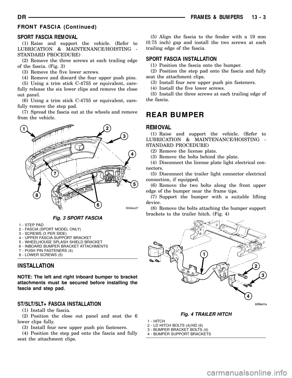
(2) Remove the three screws at each trailing edge
of the fascia. (Fig. 3)
(3) Remove the five lower screws.
(4) Remove and discard the four upper push pins.
(5) Using a trim stick C-4755 or equivalent, care-
fully release the six lower clips and remove the close
out panel.
(6) Using a trim stick C-4755 or equivalent, care-
fully remove the step pad.
(7) Spread the fascia out at the wheels and remove
from the vehicle.
INSTALLATION
NOTE: The left and right inboard bumper to bracket
attachments must be secured before installing the
fascia and step pad.
ST/SLT/SLT+ FASCIA INSTALLATION
(1) Install the fascia.
(2) Position the close out panel and seat the 6
lower clips fully.
(3) Install four new upper push pin fasteners.
(4) Position the step pad onto the fascia and fully
seat the attachment clips.(5) Align the fascia to the fender with a 19 mm
(0.75 inch) gap and install the two screws at each
trailing edge of the fascia.
SPORT FASCIA INSTALLATION
(1) Position the fascia onto the bumper.
(2) Position the step pad onto the fascia and fully
seat the attachment clips.
(3) Install four new upper push pin fasteners.
(4) Install the five lower screws.
(5) Install the three screws at each trailing edge of
the fascia.
REAR BUMPER
REMOVAL
(1) Raise and support the vehicle. (Refer to
LUBRICATION & MAINTENANCE/HOISTING -
STANDARD PROCEDURE)
(2) Remove the license plate.
(3) Remove the bolts behind the plate.
(4) Disconnect the license plate light electrical con-
nectors.
(5) Disconnect the trailer light connector electrical
connection, if equipped.
(6) Remove the two bolts along the front upper
edge of the bumper near the frame tips.
(7) Support the bumper with a suitable lifting
device.
(8) Remove the bolts attaching the bumper support
brackets to the trailer hitch. (Fig. 4)
Fig. 3 SPORT FASCIA
1 - STEP PAD
2 - FASCIA (SPORT MODEL ONLY)
3 - SCREWS (3 PER SIDE)
4 - UPPER FASCIA SUPPORT BRACKET
5 - WHEELHOUSE SPLASH SHIELD BRACKET
6 - INBOARD BUMPER BRACKET ATTACHMENTS
7 - PUSH PIN FASTENERS (4)
8 - LOWER SCREWS (5)
Fig. 4 TRAILER HITCH
1 - HITCH
2 - LD HITCH BOLTS (4)/HD (6)
3 - BUMPER BRACKET BOLTS (4)
4 - BUMPER SUPPORT BRACKETS
DRFRAMES & BUMPERS 13 - 3
FRONT FASCIA (Continued)