1998 DODGE RAM 1500 ECU
[x] Cancel search: ECUPage 1682 of 2627
(11) Install the pitman arm (Refer to 19 - STEER-
ING/LINKAGE/PITMAN ARM - INSTALLATION).
(12) Perform a wheel alignment (Refer to 2 - SUS-
PENSION/WHEEL ALIGNMENT - STANDARD
PROCEDURE).
STEERING GEAR INPUT
SHAFT SEAL
REMOVAL
(1) Remove the steering gear from the vehicle
(Refer to 19 - STEERING/GEAR - REMOVAL).
CAUTION: Do not overtighten the vise on the gear
case. This may affect the adjustment
(2) Mount the steering gear upside down over a
drain pan in a soft jawed vise.
(3) Place a drain pan under the gear and rotate
the input shaft back and forth several times lock-to-
lock to discharge the fluid from the steering gear
(4) Drain all the remaining fluid from the gear.
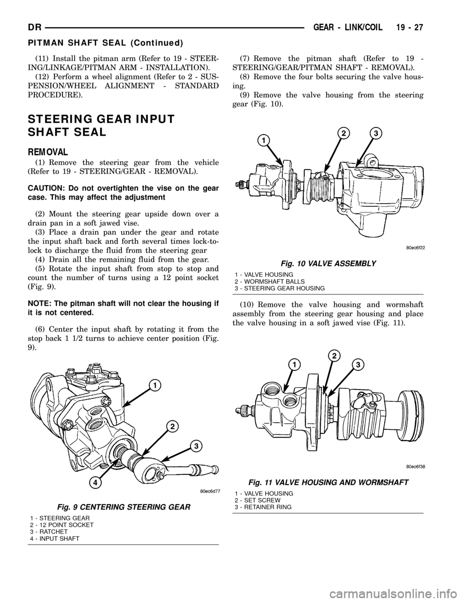
(5) Rotate the input shaft from stop to stop and
count the number of turns using a 12 point socket
(Fig. 9).
NOTE: The pitman shaft will not clear the housing if
it is not centered.
(6) Center the input shaft by rotating it from the
stop back 1 1/2 turns to achieve center position (Fig.
9).(7) Remove the pitman shaft (Refer to 19 -
STEERING/GEAR/PITMAN SHAFT - REMOVAL).
(8) Remove the four bolts securing the valve hous-
ing.
(9) Remove the valve housing from the steering
gear (Fig. 10).
(10) Remove the valve housing and wormshaft
assembly from the steering gear housing and place
the valve housing in a soft jawed vise (Fig. 11).
Fig. 9 CENTERING STEERING GEAR
1 - STEERING GEAR
2 - 12 POINT SOCKET
3 - RATCHET
4 - INPUT SHAFT
Fig. 10 VALVE ASSEMBLY
1 - VALVE HOUSING
2 - WORMSHAFT BALLS
3 - STEERING GEAR HOUSING
Fig. 11 VALVE HOUSING AND WORMSHAFT
1 - VALVE HOUSING
2 - SET SCREW
3 - RETAINER RING
DRGEAR - LINK/COIL 19 - 27
PITMAN SHAFT SEAL (Continued)
Page 1696 of 2627

(8) Fill the system with fluid and perform Steering
Pump Initial Operation, (Refer to 19 - STEERING/
PUMP - STANDARD PROCEDURE).
(9) Start the engine and run it for fifteen minutes
then stop the engine.
(10) Remove the return line/lines from the pump
and plug the pump port/ports.
(11) Pour fresh fluid into the reservoir and check
the draining fluid for contamination. If the fluid is
still contaminated, then flush the system again.
(12) Install the return line/lines and perform
Steering Pump Initial Operation, (Refer to 19 -
STEERING/PUMP - STANDARD PROCEDURE).
REMOVAL
REMOVAL - GAS
(1) Drain and siphon the power steering fluid from
the reservoir.
(2) Remove the serpentine belt.
CAUTION: Do not remove the fitting on the pump
that the high pressure hose screws into. The fitting
may come loose unless it is backed up using
another wrench. If the fitting does come loose, it
must be retightened before continuing. (57 - 67Nm,
40 - 50 lbft) If this fitting comes out of the pump
body, the internal spring and valve parts will fall out
of the pump and they cannot be reinstalled prop-
erly. If this occurs the pump needs to be replaced
with a new pump.
(3) Disconnect the return hose. (Fig. 2)
(4) Disconnect the pressure hose. (Fig. 2)
(5) Access to remove the three bolts securing the
pump to the cylinder head can be gained thru the
pulley holes. (Fig. 2)
REMOVAL - DIESEL
(1) Drain and siphon the power steering fluid from
the reservoir.
(2) Remove the serpentine belt.
CAUTION: Do not remove the fitting on the pump
that the high pressure hose screws into. The fitting
may come loose unless it is backed up using
another wrench. If the fitting does come loose, it
must be retightened before continuing. (57 - 67Nm,
40 - 50 lbft) If this fitting comes out of the pump
body, the internal spring and valve parts will fall out
of the pump and they cannot be reinstalled prop-
erly. If this occurs the pump needs to be replaced
with a new pump.
(3) Disconnect the return hose.
(4) Disconnect the pressure hose.(5) Access to remove the three bolts securing the
pump to the cylinder head can be gained thru the
pulley holes.
(6) Loosen the pump bracket to the block.
(7) Remove the 6 intake plenum bolts (Fig. 3).
(8) loosen the inner cooler tube clamp at the
intake plenum and remove the intake plenum.
(9) Loosen the inner cooler tube clamp at the radi-
ator support side and remove the tube from the vehi-
cle.
(10) Remove the power steering pump from the top
of the engine compartment where the intake plenum
was (Fig. 3).
Fig. 2 POWER STEERING PUMP
1 - POWER STEERING PULLEY
2 - POWER STEERING RESERVOIR
3 - RETURN HOSE
4 - HIGH PRESSURE HOSE
Fig. 3 POWER STEERING PUMP ACCESS
1 - INTAKE PLENUM MOUNTING
2 - POWER STEERING PUMP
DRPUMP 19 - 41
PUMP (Continued)
Page 1698 of 2627
FLUID
DESCRIPTION
The recommended fluid for the power steering sys-
tem is MopartATF +4.
MopartATF+4, when new is red in color. The
ATF+4 is dyed red so it can be identified from other
fluids used in the vehicle such as engine oil or anti-
freeze. The red color is not permanent and is not an
indicator of fluid condition, As the vehicle is driven,
the ATF+4 will begin to look darker in color and may
eventually become brown.THIS IS NORMAL.
ATF+4 also has a unique odor that may change with
age. Consequently, odor and color cannot be used to
indicate the fluid condition or the need for a fluid
change.
STANDARD PROCEDURE - POWER STEERING
FLUID LEVEL CHECKING
WARNING: FLUID LEVEL SHOULD BE CHECKED
WITH THE ENGINE OFF TO PREVENT PERSONAL
INJURY FROM MOVING PARTS.
CAUTION: MOPARTATF+4 is to be used in the
power steering system. No other power steering or
automatic transmission fluid is to be used in the
system. Damage may result to the power steering
pump and system if any other fluid is used, and do
not overfill.
The power steering fluid level can be viewed on the
dipstick attached to the filler cap. There are two
ranges listed on the dipstick, COLD and HOT. Before
opening power steering system, wipe the reservoir
filler cap free of dirt and debris. Remove the cap and
check the fluid level on its dipstick. When the fluid is
at normal ambient temperature, approximately 21ÉC
to 27ÉC (70ÉF to 80ÉF), the fluid level should read
between the minimum and maximum area of the cold
range. When the fluid is hot, fluid level is allowed to
read up to the highest end of the HOT range. Only
add fluid when the vehicle is cold.
Use only MopartATF+4Do not overfill the
power steering system.
FLUID COOLER
REMOVAL
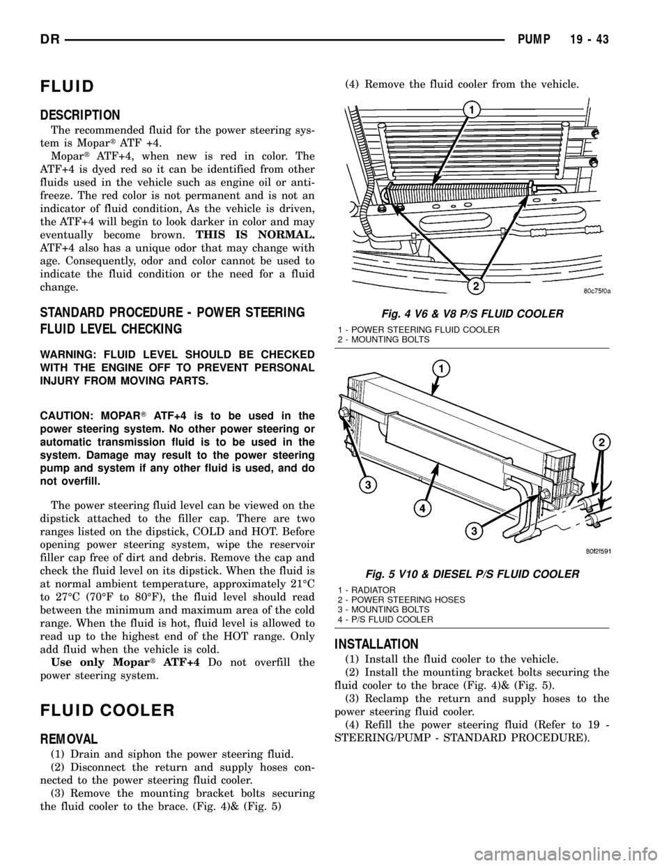
(1) Drain and siphon the power steering fluid.
(2) Disconnect the return and supply hoses con-
nected to the power steering fluid cooler.
(3) Remove the mounting bracket bolts securing
the fluid cooler to the brace. (Fig. 4)& (Fig. 5)(4) Remove the fluid cooler from the vehicle.
INSTALLATION
(1) Install the fluid cooler to the vehicle.
(2) Install the mounting bracket bolts securing the
fluid cooler to the brace (Fig. 4)& (Fig. 5).
(3) Reclamp the return and supply hoses to the
power steering fluid cooler.
(4) Refill the power steering fluid (Refer to 19 -
STEERING/PUMP - STANDARD PROCEDURE).
Fig. 4 V6 & V8 P/S FLUID COOLER
1 - POWER STEERING FLUID COOLER
2 - MOUNTING BOLTS
Fig. 5 V10 & DIESEL P/S FLUID COOLER
1 - RADIATOR
2 - POWER STEERING HOSES
3 - MOUNTING BOLTS
4 - P/S FLUID COOLER
DRPUMP 19 - 43
Page 1707 of 2627
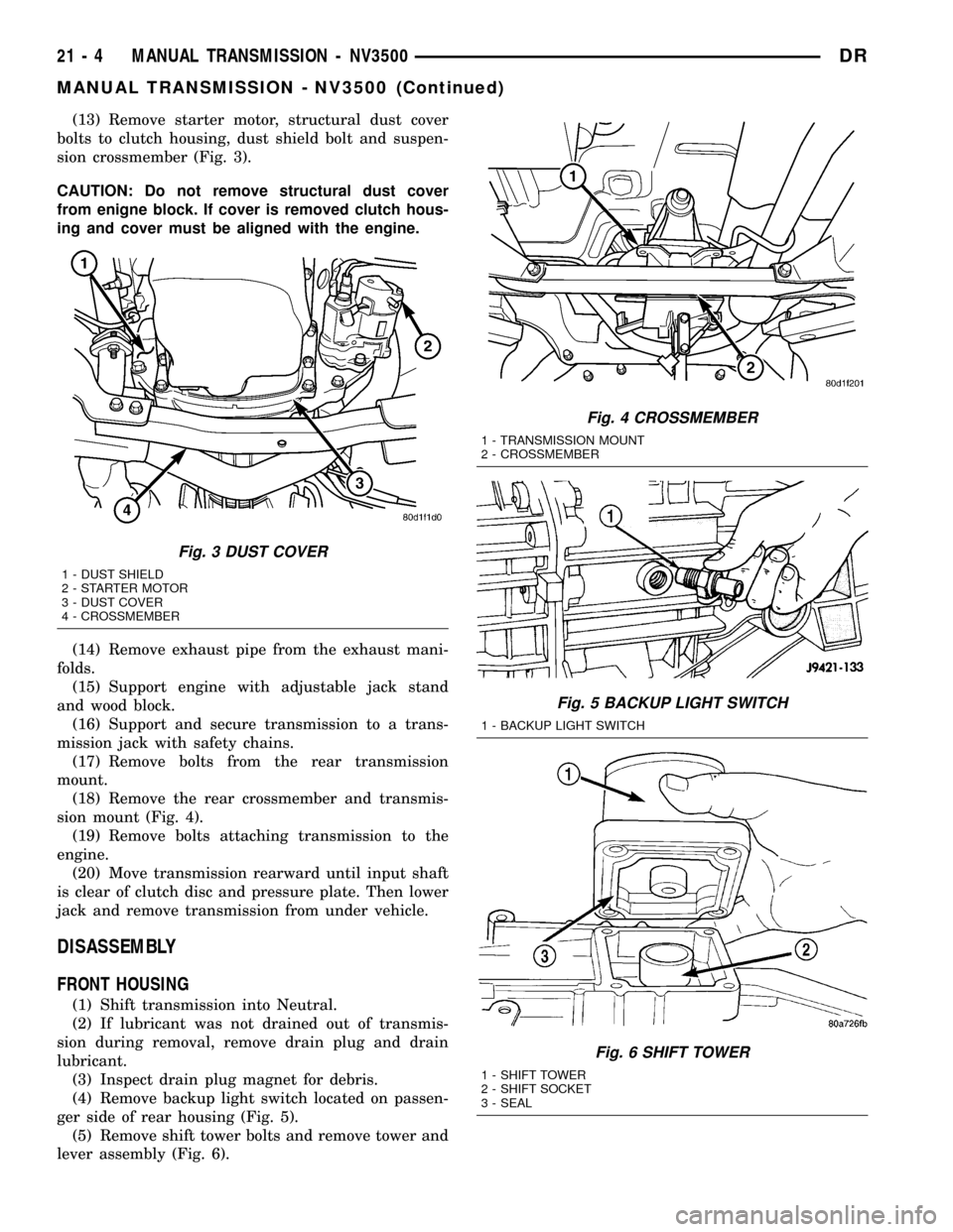
(13) Remove starter motor, structural dust cover
bolts to clutch housing, dust shield bolt and suspen-
sion crossmember (Fig. 3).
CAUTION: Do not remove structural dust cover
from enigne block. If cover is removed clutch hous-
ing and cover must be aligned with the engine.
(14) Remove exhaust pipe from the exhaust mani-
folds.
(15) Support engine with adjustable jack stand
and wood block.
(16) Support and secure transmission to a trans-
mission jack with safety chains.
(17) Remove bolts from the rear transmission
mount.
(18) Remove the rear crossmember and transmis-
sion mount (Fig. 4).
(19) Remove bolts attaching transmission to the
engine.
(20) Move transmission rearward until input shaft
is clear of clutch disc and pressure plate. Then lower
jack and remove transmission from under vehicle.
DISASSEMBLY
FRONT HOUSING
(1) Shift transmission into Neutral.
(2) If lubricant was not drained out of transmis-
sion during removal, remove drain plug and drain
lubricant.
(3) Inspect drain plug magnet for debris.
(4) Remove backup light switch located on passen-
ger side of rear housing (Fig. 5).
(5) Remove shift tower bolts and remove tower and
lever assembly (Fig. 6).
Fig. 3 DUST COVER
1 - DUST SHIELD
2 - STARTER MOTOR
3 - DUST COVER
4 - CROSSMEMBER
Fig. 4 CROSSMEMBER
1 - TRANSMISSION MOUNT
2 - CROSSMEMBER
Fig. 5 BACKUP LIGHT SWITCH
1 - BACKUP LIGHT SWITCH
Fig. 6 SHIFT TOWER
1 - SHIFT TOWER
2 - SHIFT SOCKET
3 - SEAL
21 - 4 MANUAL TRANSMISSION - NV3500DR
MANUAL TRANSMISSION - NV3500 (Continued)
Page 1708 of 2627
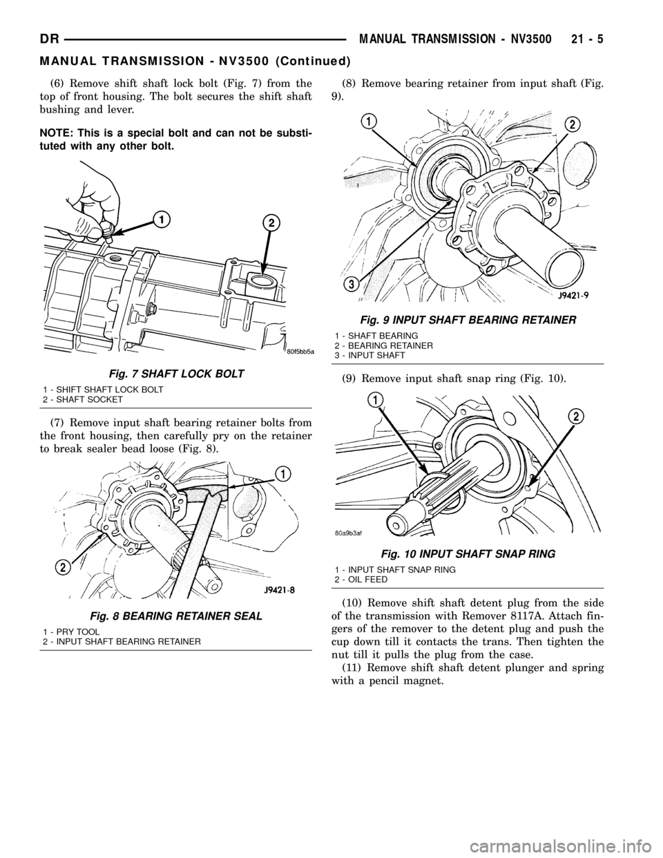
(6) Remove shift shaft lock bolt (Fig. 7) from the
top of front housing. The bolt secures the shift shaft
bushing and lever.
NOTE: This is a special bolt and can not be substi-
tuted with any other bolt.
(7) Remove input shaft bearing retainer bolts from
the front housing, then carefully pry on the retainer
to break sealer bead loose (Fig. 8).(8) Remove bearing retainer from input shaft (Fig.
9).
(9) Remove input shaft snap ring (Fig. 10).
(10) Remove shift shaft detent plug from the side
of the transmission with Remover 8117A. Attach fin-
gers of the remover to the detent plug and push the
cup down till it contacts the trans. Then tighten the
nut till it pulls the plug from the case.
(11) Remove shift shaft detent plunger and spring
with a pencil magnet.
Fig. 7 SHAFT LOCK BOLT
1 - SHIFT SHAFT LOCK BOLT
2 - SHAFT SOCKET
Fig. 8 BEARING RETAINER SEAL
1-PRYTOOL
2 - INPUT SHAFT BEARING RETAINER
Fig. 9 INPUT SHAFT BEARING RETAINER
1 - SHAFT BEARING
2 - BEARING RETAINER
3 - INPUT SHAFT
Fig. 10 INPUT SHAFT SNAP RING
1 - INPUT SHAFT SNAP RING
2 - OIL FEED
DRMANUAL TRANSMISSION - NV3500 21 - 5
MANUAL TRANSMISSION - NV3500 (Continued)
Page 1715 of 2627
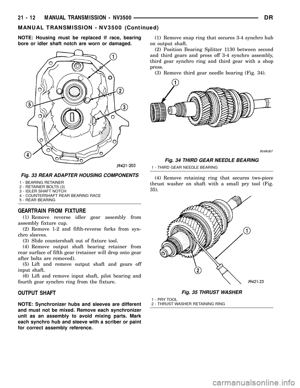
NOTE: Housing must be replaced if race, bearing
bore or idler shaft notch are worn or damaged.
GEARTRAIN FROM FIXTURE
(1) Remove reverse idler gear assembly from
assembly fixture cup.
(2) Remove 1-2 and fifth-reverse forks from syn-
chro sleeves.
(3) Slide countershaft out of fixture tool.
(4) Remove output shaft bearing retainer from
rear surface of fifth gear (retainer will drop onto gear
after bolts are removed).
(5) Lift and remove output shaft and gears off
input shaft.
(6) Lift and remove input shaft, pilot bearing and
fourth gear synchro ring from the fixture.
OUTPUT SHAFT
NOTE: Synchronizer hubs and sleeves are different
and must not be mixed. Remove each synchronizer
unit as an assembly to avoid mixing parts. Mark
each synchro hub and sleeve with a scriber or paint
for correct assembly reference.(1) Remove snap ring that secures 3-4 synchro hub
on output shaft.
(2) Position Bearing Splitter 1130 between second
and third gears and press off 3-4 synchro assembly,
third gear synchro ring and third gear with a shop
press.
(3) Remove third gear needle bearing (Fig. 34).
(4) Remove retaining ring that secures two-piece
thrust washer on shaft with a small pry tool (Fig.
35).
Fig. 33 REAR ADAPTER HOUSING COMPONENTS
1 - BEARING RETAINER
2 - RETAINER BOLTS (3)
3 - IDLER SHAFT NOTCH
4 - COUNTERSHAFT REAR BEARING RACE
5 - REAR BEARING
Fig. 34 THIRD GEAR NEEDLE BEARING
1 - THIRD GEAR NEEDLE BEARING
Fig. 35 THRUST WASHER
1-PRYTOOL
2 - THRUST WASHER RETAINING RING
21 - 12 MANUAL TRANSMISSION - NV3500DR
MANUAL TRANSMISSION - NV3500 (Continued)
Page 1719 of 2627

INSPECTION
SHIFT LEVER ASSEMBLY
The shift lever assembly is not serviceable. Replace
the lever and shift tower as an assembly if the tower,
lever, lever ball or internal components are worn or
damaged.
SHIFT SHAFT AND FORKS
Inspect the shift fork interlock arms and synchro
sleeve contact surfaces (Fig. 48). Replace any fork
exhibiting wear or damage in these areas. Do not
attempt to salvage shift forks.
Check condition of the shift shaft detent plunger
and spring. The plunger should be smooth and free of
nicks or scores. The plunger spring should be
straight and not collapsed, or distorted. Minor
scratches or nicks on the plunger can be smoothed
with 320/400 grit emery soaked in oil. Replace the
plunger and spring if in doubt about condition. Check
condition of detent plunger bushings. Replace if dam-
aged.
Inspect shift shaft, shift shaft bushing, bearing,
shaft lever and lever bushing that fits over the lever.
Replace shaft if bent, cracked or severely scored.
Minor burrs, nicks or scratches can be smoothed off
with 320/400 grit emery cloth followed by polishing
with crocus cloth. Replace the shift shaft bushing or
bearing if damaged.Replace the shaft lever and bushing if either part
is deformed, or worn. Do not attempt to salvage these
parts as shift fork binding will occur. Replace the roll
pin that secures the lever to the shaft.
FRONT/REAR HOUSINGS AND BEARING
RETAINERS
Inspect the housings carefully. Look for cracks,
stripped threads, scored mating surfaces, damaged
bearing bores or worn dowel pin holes. Minor nicks
on mating surfaces can be dressed off with a fine file
or emery cloth. Damaged threads can be renewed by
either re-tapping or installing Helicoil inserts.
NOTE: The front housing contains the countershaft
front bearing race. The rear housing contains the
countershaft rear bearing race. These components
are NOT serviceable items. The front housing will
have to be replaced if the countershaft bearing race
is loose, worn or damaged. The rear housing will
have to be replaced if the countershaft rear bearing
race is loose, worn or damaged.
Inspect the input shaft bearing retainer. Be sure
the release bearing slide surface of the retainer is in
good condition. Minor nicks on the surface can be
smoothed off with 320/420 grit emery cloth and final
polished with oil coated crocus cloth. Replace the
retainer seal if necessary.
Fig. 48 Shift Forks And Shaft
1 - SHIFT SHAFT
2 - SHAFT LEVER
3 - SHAFT LEVER BUSHING4 - 3-4 SHIFT FORK
5 - 1-2 SHIFT FORK
6 - FIFTH-REVERSE SHIFT FORK
21 - 16 MANUAL TRANSMISSION - NV3500DR
MANUAL TRANSMISSION - NV3500 (Continued)
Page 1720 of 2627

Inspect output shaft bearing retainer, the
U-shaped retainer must be flat and free of distortion.
Replace the retainer if the threads are damaged or if
the retainer is bent or cracked.
COUNTERSHAFT BEARINGS AND RACES
The countershaft bearings and races are machine
lapped during manufacture to form matched sets.
The bearings and races should not be interchanged.
NOTE: The bearing races are a permanent press fit
in the housings and are NOT serviceable. If a bear-
ing race becomes damaged, the front or rear hous-
ing must be replaced. A new countershaft bearing
will be supplied with each new housing for service
use.
REVERSE IDLER COMPONENTS
Inspect the idler gear, bearing, shaft, thrust
washer, wave washer and thrust plate. Replace the
bearing if any of the needle bearing rollers are worn,
chipped, cracked, flat-spotted or brinnelled. Also
replace the bearing if the plastic bearing cage is
damaged or distorted.
Replace thrust washer, wave washer or thrust
plate if cracked, chipped or worn. Replace idler gear
if the teeth are chipped, cracked or worn thin.
Replace shaft if worn, scored or the bolt threads are
damaged beyond repair. Replace support segment if
cracked or chipped and replace the idler attaching
bolts if the threads are damaged.
Shift Socket
Inspect the shift socket for wear or damage.
Replace the socket if the roll pin or shift shaft bores
are damaged. Minor nicks in the shift lever ball seat
in the socket can be smoothed down with 400 grit
emery or wet/dry paper. Replace the socket if the ball
seat is worn or cracked. Do not reuse the original
shift socket roll pin. Install anewpin during assem-
bly. The socket roll pin is approximately 33 mm
(1-1/4 in.) long.
Output Shaft And Geartrain
Inspect all gears for worn, cracked, chipped or bro-
ken teeth. Also check condition of the bearing bore in
each gear. The bores should be smooth and free of
surface damage. Discoloration of the gear bores is a
normal occurrence and is not a reason for replace-
ment. Replace gears only when tooth damage has
occurred or if the bores are brinnelled or severely
scored.
Inspect the shaft splines and bearings surfaces.
Minor nicks on the bearing surfaces can be smoothed
with 320/420 grit emery and final polished with cro-
cus cloth. Replace the shaft if the splines are dam-aged or bearing surfaces are deeply scored, worn or
brinnelled.
ASSEMBLY
NOTE: Sealers are used at all case joints. Use
Mopar Gasket Maker or equivalent for all case joints
and Mopar silicone sealer or equivalent for the
input shaft bearing retainer.
SYNCHRONIZER
(1) Slide sleeve onto the hub, leaving enough room
to install the spring in the hub and strut in the hub
groove.
(2) Install first spring in the hub, then install a
strut over the spring. Verify spring is seated in the
spring bore in the strut.
(3) Slide sleeve onto the hub far enough to hold
the first strut and spring in place.
(4) Place detent ball in the top of the strut, then
press the ball into place with a small screwdriver.
Work the sleeve over the ball to hold it in place.
(5) Repeat procedure for the remaining springs,
struts and balls. Use tape or rubber bands to tempo-
rarily secure each strut and ball as they are
installed.
(6) Verify the synchro three springs, struts and
detent balls are all in place (Fig. 49).
Fig. 49 SYNCHRONIZER COMPONENTS
1 - SLEEVE
2 - HUB SHOULDER
3 - SPRING (3)
4 - STRUT (3)
5 - DETENT BALL (3)
6 - HUB
DRMANUAL TRANSMISSION - NV3500 21 - 17
MANUAL TRANSMISSION - NV3500 (Continued)