1998 DODGE RAM 1500 ECU
[x] Cancel search: ECUPage 1550 of 2627
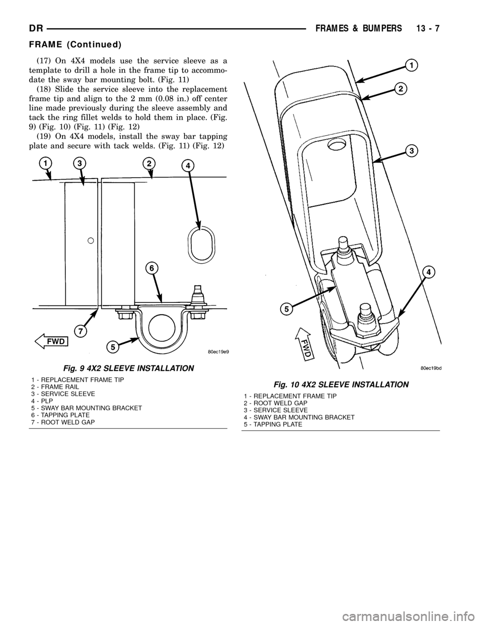
(17) On 4X4 models use the service sleeve as a
template to drill a hole in the frame tip to accommo-
date the sway bar mounting bolt. (Fig. 11)
(18) Slide the service sleeve into the replacement
frame tip and align to the 2 mm (0.08 in.) off center
line made previously during the sleeve assembly and
tack the ring fillet welds to hold them in place. (Fig.
9) (Fig. 10) (Fig. 11) (Fig. 12)
(19) On 4X4 models, install the sway bar tapping
plate and secure with tack welds. (Fig. 11) (Fig. 12)
Fig. 9 4X2 SLEEVE INSTALLATION
1 - REPLACEMENT FRAME TIP
2 - FRAME RAIL
3 - SERVICE SLEEVE
4 - PLP
5 - SWAY BAR MOUNTING BRACKET
6 - TAPPING PLATE
7 - ROOT WELD GAPFig. 10 4X2 SLEEVE INSTALLATION
1 - REPLACEMENT FRAME TIP
2 - ROOT WELD GAP
3 - SERVICE SLEEVE
4 - SWAY BAR MOUNTING BRACKET
5 - TAPPING PLATE
DRFRAMES & BUMPERS 13 - 7
FRAME (Continued)
Page 1576 of 2627
REMOVAL
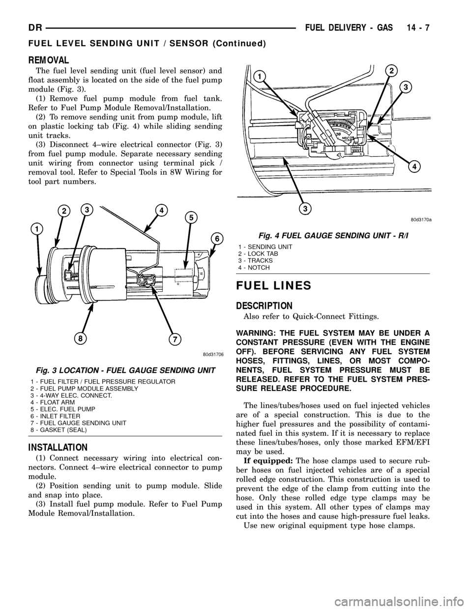
The fuel level sending unit (fuel level sensor) and
float assembly is located on the side of the fuel pump
module (Fig. 3).
(1) Remove fuel pump module from fuel tank.
Refer to Fuel Pump Module Removal/Installation.
(2) To remove sending unit from pump module, lift
on plastic locking tab (Fig. 4) while sliding sending
unit tracks.
(3) Disconnect 4±wire electrical connector (Fig. 3)
from fuel pump module. Separate necessary sending
unit wiring from connector using terminal pick /
removal tool. Refer to Special Tools in 8W Wiring for
tool part numbers.
INSTALLATION
(1) Connect necessary wiring into electrical con-
nectors. Connect 4±wire electrical connector to pump
module.
(2) Position sending unit to pump module. Slide
and snap into place.
(3) Install fuel pump module. Refer to Fuel Pump
Module Removal/Installation.
FUEL LINES
DESCRIPTION
Also refer to Quick-Connect Fittings.
WARNING: THE FUEL SYSTEM MAY BE UNDER A
CONSTANT PRESSURE (EVEN WITH THE ENGINE
OFF). BEFORE SERVICING ANY FUEL SYSTEM
HOSES, FITTINGS, LINES, OR MOST COMPO-
NENTS, FUEL SYSTEM PRESSURE MUST BE
RELEASED. REFER TO THE FUEL SYSTEM PRES-
SURE RELEASE PROCEDURE.
The lines/tubes/hoses used on fuel injected vehicles
are of a special construction. This is due to the
higher fuel pressures and the possibility of contami-
nated fuel in this system. If it is necessary to replace
these lines/tubes/hoses, only those marked EFM/EFI
may be used.
If equipped:The hose clamps used to secure rub-
ber hoses on fuel injected vehicles are of a special
rolled edge construction. This construction is used to
prevent the edge of the clamp from cutting into the
hose. Only these rolled edge type clamps may be
used in this system. All other types of clamps may
cut into the hoses and cause high-pressure fuel leaks.
Use new original equipment type hose clamps.
Fig. 3 LOCATION - FUEL GAUGE SENDING UNIT
1 - FUEL FILTER / FUEL PRESSURE REGULATOR
2 - FUEL PUMP MODULE ASSEMBLY
3 - 4-WAY ELEC. CONNECT.
4 - FLOAT ARM
5 - ELEC. FUEL PUMP
6 - INLET FILTER
7 - FUEL GAUGE SENDING UNIT
8 - GASKET (SEAL)
Fig. 4 FUEL GAUGE SENDING UNIT - R/I
1 - SENDING UNIT
2 - LOCK TAB
3 - TRACKS
4 - NOTCH
DRFUEL DELIVERY - GAS 14 - 7
FUEL LEVEL SENDING UNIT / SENSOR (Continued)
Page 1626 of 2627

FUEL LEVEL SENDING UNIT /
SENSOR
DESCRIPTION
The fuel gauge sending unit (fuel level sensor) is
attached to the side of the fuel tank module. The
sending unit consists of a float, an arm, and a vari-
able resistor track (card).
OPERATION
The fuel tank module on diesel powered models
has 2 different circuits (wires). Two of these circuits
are used at the fuel gauge sending unit for fuel
gauge operation. The diesel engine does not have a
fuel tank module mounted electric fuel pump. The
electric fuel pump (fuel transfer pump) is mounted to
the engine.
For Fuel Gauge Operation:A constant input
voltage source of about 12 volts (battery voltage) is
supplied to the resistor track on the fuel gauge send-
ing unit. This is fed directly from the Engine Control
Module (ECM).NOTE: For diagnostic purposes,
this 12V power source can only be verified with
the circuit opened (fuel tank module electrical
connector unplugged). With the connectors
plugged, output voltages will vary from about .6
volts at FULL, to about 7.0 volts at EMPTY.The
resistor track is used to vary the voltage (resistance)
depending on fuel tank float level. As fuel level
increases, the float and arm move up, which
decreases voltage. As fuel level decreases, the float
and arm move down, which increases voltage. The
varied voltage signal is returned back to the ECM
through the sensor return circuit.
Both of the electrical circuits between the fuel
gauge sending unit and the ECM are hard-wired (not
multi-plexed). After the voltage signal is sent from
the resistor track, and back to the ECM, the ECM
will interpret the resistance (voltage) data and send
a message across the multi-plex bus circuits to the
instrument panel cluster. Here it is translated into
the appropriate fuel gauge level reading. Refer to
Instrument Panel for additional information.
REMOVAL
REMOVAL/INSTALLATION
For diesel removal and installation procedures,
refer to the gas section of Fuel System/Fuel Delivery.
See Fuel Level Sending Unit/Sensor Removal/Instal-
lation.
FUEL LINES
DESCRIPTION
Low-Pressure Lines Are:
²the fuel supply line from fuel tank to fuel trans-
fer (lift) pump.
²the fuel return line back to fuel tank.
²the fuel drain (manifold) line at rear of cylinder
head.
²the fuel supply line from fuel filter to fuel injec-
tion pump.
²the fuel injection pump return line.
High-Pressure Lines Are:
²the fuel line from fuel injection pump to fuel
rail.
²the 6 fuel lines from fuel rail up to injector con-
nector tubes
WARNING: HIGH-PRESSURE FUEL LINES DELIVER
DIESEL FUEL UNDER EXTREME PRESSURE FROM
THE INJECTION PUMP TO THE FUEL INJECTORS.
THIS MAY BE AS HIGH AS 160,000 KPA (23,206
PSI). USE EXTREME CAUTION WHEN INSPECTING
FOR HIGH-PRESSURE FUEL LEAKS. INSPECT FOR
HIGH-PRESSURE FUEL LEAKS WITH A SHEET OF
CARDBOARD. HIGH FUEL INJECTION PRESSURE
CAN CAUSE PERSONAL INJURY IF CONTACT IS
MADE WITH THE SKIN.
OPERATION
High-Pressure Lines
CAUTION: The high-pressure fuel lines must be
held securely in place in their holders. The lines
cannot contact each other or other components. Do
not attempt to weld high-pressure fuel lines or to
repair lines that are damaged. If lines are ever
kinked or bent, they must be replaced. Use only the
recommended lines when replacement of high-pres-
sure fuel line is necessary.
High-pressure fuel lines deliver fuel (under pres-
sure) of up to approximately 160,000 kPa (23,206
PSI) from the injection pump to the fuel injectors.
The lines expand and contract from the high-pres-
sure fuel pulses generated during the injection pro-
cess. All high-pressure fuel lines are of the same
length and inside diameter. Correct high-pressure
fuel line usage and installation is critical to smooth
engine operation.
DRFUEL DELIVERY - DIESEL 14 - 57
Page 1627 of 2627
WARNING: USE EXTREME CAUTION WHEN
INSPECTING FOR HIGH-PRESSURE FUEL LEAKS.
INSPECT FOR HIGH-PRESSURE FUEL LEAKS WITH
A SHEET OF CARDBOARD. HIGH FUEL INJECTION
PRESSURE CAN CAUSE PERSONAL INJURY IF
CONTACT IS MADE WITH THE SKIN.
DIAGNOSIS AND TESTING - HIGH-PRESSURE
FUEL LINE LEAKS
High-pressure fuel line leaks can cause starting
problems and poor engine performance.
WARNING: DUE TO EXTREME FUEL PRESSURES
OF UP TO 160,000 kPa (23,206 PSI), USE EXTREME
CAUTION WHEN INSPECTING FOR HIGH-PRES-
SURE FUEL LEAKS. DO NOT GET YOUR HAND OR
A FINGER NEAR A SUSPECTED LEAK. INSPECT
FOR HIGH-PRESSURE FUEL LEAKS WITH A SHEET
OF CARDBOARD. HIGH FUEL INJECTION PRES-
SURE CAN CAUSE PERSONAL INJURY IF CON-
TACT IS MADE WITH THE SKIN.
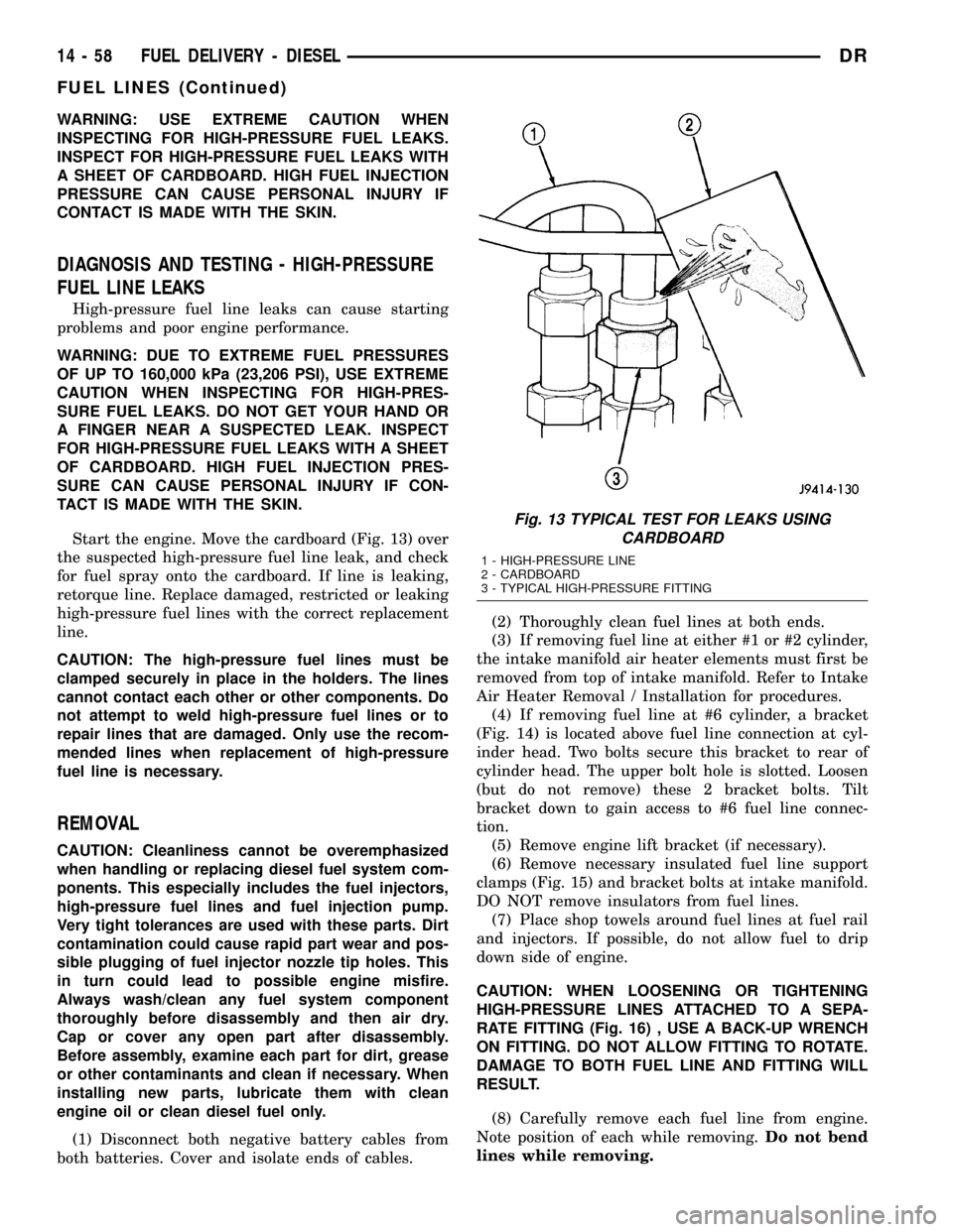
Start the engine. Move the cardboard (Fig. 13) over
the suspected high-pressure fuel line leak, and check
for fuel spray onto the cardboard. If line is leaking,
retorque line. Replace damaged, restricted or leaking
high-pressure fuel lines with the correct replacement
line.
CAUTION: The high-pressure fuel lines must be
clamped securely in place in the holders. The lines
cannot contact each other or other components. Do
not attempt to weld high-pressure fuel lines or to
repair lines that are damaged. Only use the recom-
mended lines when replacement of high-pressure
fuel line is necessary.
REMOVAL
CAUTION: Cleanliness cannot be overemphasized
when handling or replacing diesel fuel system com-
ponents. This especially includes the fuel injectors,
high-pressure fuel lines and fuel injection pump.
Very tight tolerances are used with these parts. Dirt
contamination could cause rapid part wear and pos-
sible plugging of fuel injector nozzle tip holes. This
in turn could lead to possible engine misfire.
Always wash/clean any fuel system component
thoroughly before disassembly and then air dry.
Cap or cover any open part after disassembly.
Before assembly, examine each part for dirt, grease
or other contaminants and clean if necessary. When
installing new parts, lubricate them with clean
engine oil or clean diesel fuel only.
(1) Disconnect both negative battery cables from
both batteries. Cover and isolate ends of cables.(2) Thoroughly clean fuel lines at both ends.
(3) If removing fuel line at either #1 or #2 cylinder,
the intake manifold air heater elements must first be
removed from top of intake manifold. Refer to Intake
Air Heater Removal / Installation for procedures.
(4) If removing fuel line at #6 cylinder, a bracket
(Fig. 14) is located above fuel line connection at cyl-
inder head. Two bolts secure this bracket to rear of
cylinder head. The upper bolt hole is slotted. Loosen
(but do not remove) these 2 bracket bolts. Tilt
bracket down to gain access to #6 fuel line connec-
tion.
(5) Remove engine lift bracket (if necessary).
(6) Remove necessary insulated fuel line support
clamps (Fig. 15) and bracket bolts at intake manifold.
DO NOT remove insulators from fuel lines.
(7) Place shop towels around fuel lines at fuel rail
and injectors. If possible, do not allow fuel to drip
down side of engine.
CAUTION: WHEN LOOSENING OR TIGHTENING
HIGH-PRESSURE LINES ATTACHED TO A SEPA-
RATE FITTING (Fig. 16) , USE A BACK-UP WRENCH
ON FITTING. DO NOT ALLOW FITTING TO ROTATE.
DAMAGE TO BOTH FUEL LINE AND FITTING WILL
RESULT.
(8) Carefully remove each fuel line from engine.
Note position of each while removing.Do not bend
lines while removing.
Fig. 13 TYPICAL TEST FOR LEAKS USING
CARDBOARD
1 - HIGH-PRESSURE LINE
2 - CARDBOARD
3 - TYPICAL HIGH-PRESSURE FITTING
14 - 58 FUEL DELIVERY - DIESELDR
FUEL LINES (Continued)
Page 1640 of 2627
INSTALLATION
Engine Mounted Sensor :
The APPS is serviced (replaced) as one assembly
including the lever, brackets and sensor. The APPS is
calibrated to its mounting bracket.
(1) Snap electrical connector into bottom of sensor.
(2) Position APPS assembly to engine and install 6
bolts. Tighten bolts to 24 N´m (18 ft. lbs.) torque.
(3) Connect wiring harness clip at bottom of
bracket.
(4) Refer to Group 21, Transmission for transmis-
sion control cable installation procedures.
(5) Install speed control cable into mounting
bracket. Be sure pinch tabs have secured cable.
(6) Install throttle cable into mounting bracket. Be
sure pinch tabs have secured cable.
(7) Connect throttle cable at lever (snaps on).
(8) Connect speed control cable to lever by pushing
cable connector rearward onto lever pin while hold-
ing lever forward.
(9) Install cable cover.
(10) Connect both negative battery cables to both
batteries.
(11) If necessary, use DRB IIItScan Tool to erase
any Diagnostic Trouble Codes (DTC's) from ECM.Battery Tray Mounted Sensor :
(1) Install Accelerator Pedal Position Sensor
(APPS) cable to accelerator pedal. Refer to Accelera-
tor Pedal Removal / Installation.
(2) Connect electrical connector to APPS.
(3) If necessary, connect cable to APPS lever ball
socket (snaps on).
(4) Snap APPS cable cover closed.
(5) Position APPS assembly to bottom of battery
tray and install 3 bolts. Refer to Torque Specifica-
tions.
(6) Install wheelhouse liner. Refer to Body.
(7) Perform the following procedure:
(a) Connect negative battery cables to both bat-
teries.
(b) Turn key switch ON, but do not crank
engine.
(c) Leave key switch ON for a minimum of 10
seconds. This will allow ECM to learn electrical
parameters.
(8) If necessary, use DRB IIItScan Tool to erase
any Diagnostic Trouble Codes (DTC's) from ECM.
CAMSHAFT POSITION
SENSOR
DESCRIPTION
The Camshaft Position Sensor (CMP) on the 5.9L
diesel engine is located below the fuel injection
pump. It is bolted to the back of the timing gear
housing.
OPERATION
The diesel Camshaft Position Sensor (CMP) con-
tains a hall effect device. A rotating target wheel
(tonewheel) for the CMP is located on the camshaft
gear. This hall effect device detects notches located
on the back side of the camshaft gear. As the cam-
shaft gear rotates, the notches pass the tip of the
CMP.
When the leading edge of the notch passes the tip
of the CMP, the following occurs: The interruption of
magnetic field causes the voltage to switch high
resulting in a signal of approximately 5 volts.
When the trailing edge of the notch passes the tip
of the CMP, the following occurs: The change of the
magnetic field causes the signal voltage to switch low
to 0 volts.
The CMP (Fig. 8) provides a signal to the Engine
Control Module (ECM) at all times when the engine
is running. The ECM uses the CMP information pri-
marily on engine start-up. Once the engine is run-
ning, the ECM uses the CMP as a backup sensor for
engine speed. The Crankshaft Position Sensor (CKP)
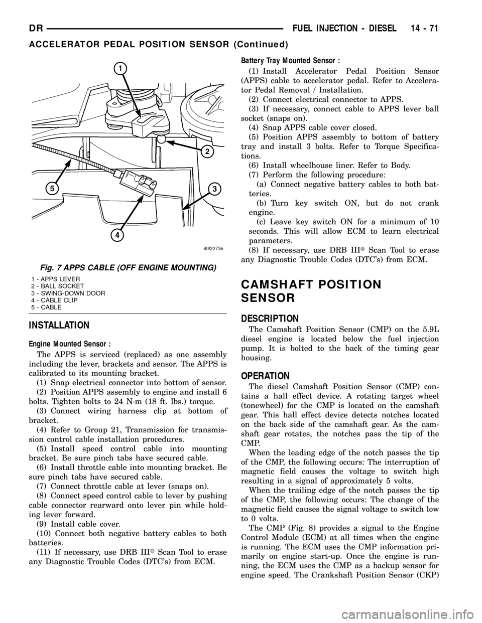
Fig. 7 APPS CABLE (OFF ENGINE MOUNTING)
1 - APPS LEVER
2 - BALL SOCKET
3 - SWING-DOWN DOOR
4 - CABLE CLIP
5 - CABLE
DRFUEL INJECTION - DIESEL 14 - 71
ACCELERATOR PEDAL POSITION SENSOR (Continued)
Page 1653 of 2627
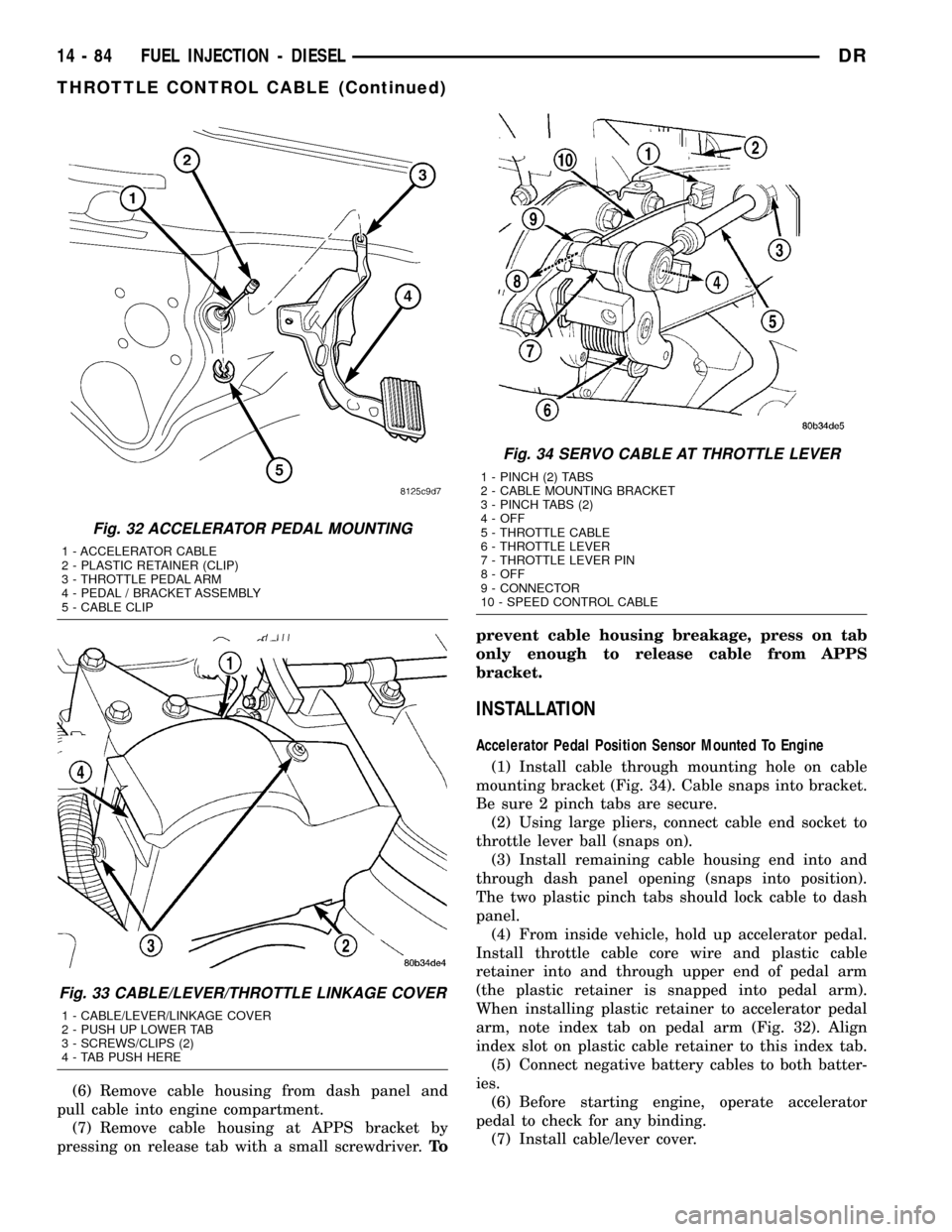
(6) Remove cable housing from dash panel and
pull cable into engine compartment.
(7) Remove cable housing at APPS bracket by
pressing on release tab with a small screwdriver.Toprevent cable housing breakage, press on tab
only enough to release cable from APPS
bracket.
INSTALLATION
Accelerator Pedal Position Sensor Mounted To Engine
(1) Install cable through mounting hole on cable
mounting bracket (Fig. 34). Cable snaps into bracket.
Be sure 2 pinch tabs are secure.
(2) Using large pliers, connect cable end socket to
throttle lever ball (snaps on).
(3) Install remaining cable housing end into and
through dash panel opening (snaps into position).
The two plastic pinch tabs should lock cable to dash
panel.
(4) From inside vehicle, hold up accelerator pedal.
Install throttle cable core wire and plastic cable
retainer into and through upper end of pedal arm
(the plastic retainer is snapped into pedal arm).
When installing plastic retainer to accelerator pedal
arm, note index tab on pedal arm (Fig. 32). Align
index slot on plastic cable retainer to this index tab.
(5) Connect negative battery cables to both batter-
ies.
(6) Before starting engine, operate accelerator
pedal to check for any binding.
(7) Install cable/lever cover.
Fig. 32 ACCELERATOR PEDAL MOUNTING
1 - ACCELERATOR CABLE
2 - PLASTIC RETAINER (CLIP)
3 - THROTTLE PEDAL ARM
4 - PEDAL / BRACKET ASSEMBLY
5 - CABLE CLIP
Fig. 33 CABLE/LEVER/THROTTLE LINKAGE COVER
1 - CABLE/LEVER/LINKAGE COVER
2 - PUSH UP LOWER TAB
3 - SCREWS/CLIPS (2)
4 - TAB PUSH HERE
Fig. 34 SERVO CABLE AT THROTTLE LEVER
1 - PINCH (2) TABS
2 - CABLE MOUNTING BRACKET
3 - PINCH TABS (2)
4 - OFF
5 - THROTTLE CABLE
6 - THROTTLE LEVER
7 - THROTTLE LEVER PIN
8 - OFF
9 - CONNECTOR
10 - SPEED CONTROL CABLE
14 - 84 FUEL INJECTION - DIESELDR
THROTTLE CONTROL CABLE (Continued)
Page 1668 of 2627
(2) Cycle the key from ACC to RUN and ensure
that the blocker does not stick or bind.
(3) Turn the key to the OFF position and ensure
that the shifter will not pull from the PARK position.
(4) Connect the over drive switch harness (if
equipped).
NOTE: Route and tie off harness to original loca-
tion.
(5) Connect the shift cable to the lever.
(6) Ensure the gear shift lever and transmission
are in the PARK position and snap the cable adjust
clip in place.
(7) Install a new brake light switch (Refer to 8 -
ELECTRICAL/LAMPS/LIGHTING - EXTERIOR/
BRAKE LAMP SWITCH - INSTALLATION).
(8) Install the SKIM and halo.
(9) Install the upper and lower column shroud.
(10) Install the column back into place and
tighten.
(11) Install the kneeblocker. (Refer to 23 - BODY/
INSTRUMENT PANEL/KNEE BLOCKER - INSTAL-
LATION).
UPPER STEERING COUPLING
REMOVAL
(1) Disconnect the negative battery cable.
NOTE: The steering column on vehicles with an
automatic transmission may not be equipped with
an internal locking shaft that allows the ignition key
cylinder to be locked with the key. Alternative meth-
ods of locking the steering wheel for service will
have to be used.(2) Lock the steering wheel with the tire in the
straight position.
(3) Remove and discard the lower pinch bolt.
(4) Lower the steering coupler shaft from the col-
umn.
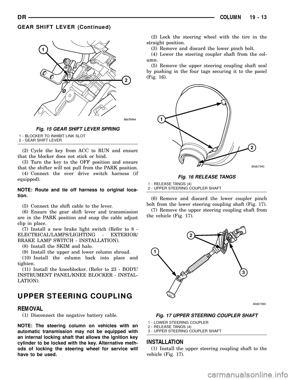
(5) Remove the upper steering coupling shaft seal
by pushing in the four tags securing it to the panel
(Fig. 16).
(6) Remove and discard the lower coupler pinch
bolt from the lower steering coupling shaft (Fig. 17).
(7) Remove the upper steering coupling shaft from
the vehicle (Fig. 17).
INSTALLATION
(1) Install the upper steering coupling shaft to the
vehicle (Fig. 17).
Fig. 15 GEAR SHIFT LEVER SPRING
1 - BLOCKER TO INHIBIT LINK SLOT
2 - GEAR SHIFT LEVER
Fig. 16 RELEASE TANGS
1 - RELEASE TANGS (4)
2 - UPPER STEERING COUPLER SHAFT
Fig. 17 UPPER STEERING COUPLER SHAFT
1 - LOWER STEERING COUPLER
2 - RELEASE TANGS (4)
3 - UPPER STEERING COUPLER SHAFT
DRCOLUMN 19 - 13
GEAR SHIFT LEVER (Continued)
Page 1669 of 2627
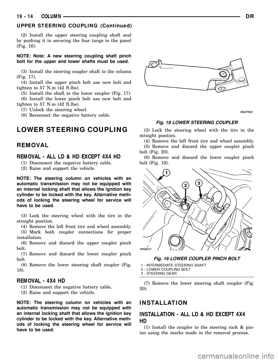
(2) Install the upper steering coupling shaft seal
by pushing it in securing the four tangs to the panel
(Fig. 16).
NOTE: Note: A new steering coupling shaft pinch
bolt for the upper and lower shafts must be used.
(3) Install the steering coupler shaft to the column
(Fig. 17).
(4) Install the upper pinch bolt use new bolt and
tighten to 57 N.m (42 ft.lbs).
(5) Install the shaft to the lower coupler (Fig. 17).
(6) Install the lower pinch bolt use new bolt and
tighten to 57 N.m (42 ft.lbs).
(7) Unlock the steering wheel.
(8) Reconnect the negative battery cable.
LOWER STEERING COUPLING
REMOVAL
REMOVAL - ALL LD & HD EXCEPT 4X4 HD
(1) Disconnect the negative battery cable.
(2) Raise and support the vehicle.
NOTE: The steering column on vehicles with an
automatic transmission may not be equipped with
an internal locking shaft that allows the ignition key
cylinder to be locked with the key. Alternative meth-
ods of locking the steering wheel for service will
have to be used.
(3) Lock the steering wheel with the tire in the
straight position.
(4) Remove the left front tire and wheel assembly.
(5) Mark both coupler connections for proper
installation.
(6) Remove and discard the upper coupler pinch
bolt.
(7) Remove and discard the lower coupler pinch
bolt.
(8) Remove the lower steering shaft coupler (Fig.
18).
REMOVAL - 4X4 HD
(1) Disconnect the negative battery cable.
(2) Raise and support the vehicle.
NOTE: The steering column on vehicles with an
automatic transmission may not be equipped with
an internal locking shaft that allows the ignition key
cylinder to be locked with the key. Alternative meth-
ods of locking the steering wheel for service will
have to be used.(3) Lock the steering wheel with the tire in the
straight position.
(4) Remove the left front tire and wheel assembly.
(5) Remove and discard the upper coupler pinch
bolt (Fig. 20).
(6) Remove and discard the lower coupler pinch
bolt (Fig. 19).
(7) Remove the lower steering shaft coupler (Fig.
20).
INSTALLATION
INSTALLATION - ALL LD & HD EXCEPT 4X4
HD
(1) Install the coupler to the steering rack & pin-
ion using the marks made in the removal process.
Fig. 18 LOWER STEERING COUPLER
Fig. 19 LOWER COUPLER PINCH BOLT
1 - INTERMEDIATE STEERING SHAFT
2 - LOWER COUPLING BOLT
3 - STEERING GEAR
19 - 14 COLUMNDR
UPPER STEERING COUPLING (Continued)