1998 DODGE RAM 1500 Governor component
[x] Cancel search: Governor componentPage 1835 of 2627

AUTOMATIC TRANSMISSION -
48RE
DESCRIPTION
The 48RE (Fig. 1) is a four speed fully automatic
transmissions with an electronic governor. The 48RE
is equipped with a lock-up clutch in the torque con-
verter. First through third gear ranges are provided
by the clutches, bands, overrunning clutch, and plan-
etary gear sets in the transmission. Fourth gear
range is provided by the overdrive unit that contains
an overdrive clutch, direct clutch, planetary gear set,
and overrunning clutch.
The transmission contains a front, rear, and direct
clutch which function as the input driving compo-
nents. It also contains the kickdown (front) and thelow/reverse (rear) bands which, along with the over-
running clutch and overdrive clutch, serve as the
holding components. The driving and holding compo-
nents combine to select the necessary planetary gear
components, in the front, rear, or overdrive planetary
gear set, transfer the engine power from the input
shaft through to the output shaft.
The valve body is mounted to the lower side of the
transmission and contains the valves to control pres-
sure regulation, fluid flow control, and clutch/band
application. The oil pump is mounted at the front of
the transmission and is driven by the torque con-
verter hub. The pump supplies the oil pressure nec-
essary for clutch/band actuation and transmission
lubrication.
21 - 132 AUTOMATIC TRANSMISSION - 48REDR
Page 1850 of 2627

CONDITION POSSIBLE CAUSES CORRECTION
DELAYED ENGAGEMENT
(FROM NEUTRAL TO
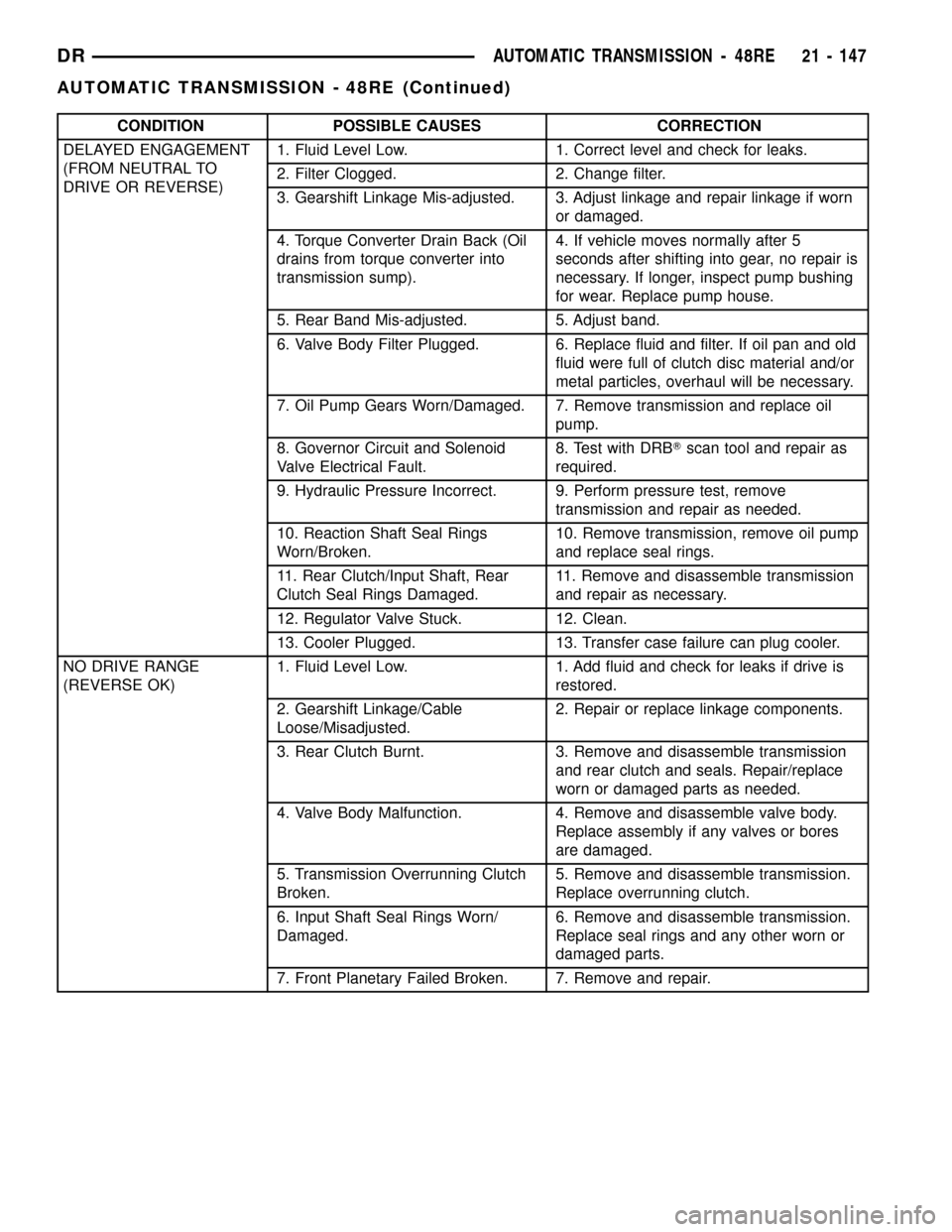
DRIVE OR REVERSE)1. Fluid Level Low. 1. Correct level and check for leaks.
2. Filter Clogged. 2. Change filter.
3. Gearshift Linkage Mis-adjusted. 3. Adjust linkage and repair linkage if worn
or damaged.
4. Torque Converter Drain Back (Oil
drains from torque converter into
transmission sump).4. If vehicle moves normally after 5
seconds after shifting into gear, no repair is
necessary. If longer, inspect pump bushing
for wear. Replace pump house.
5. Rear Band Mis-adjusted. 5. Adjust band.
6. Valve Body Filter Plugged. 6. Replace fluid and filter. If oil pan and old
fluid were full of clutch disc material and/or
metal particles, overhaul will be necessary.
7. Oil Pump Gears Worn/Damaged. 7. Remove transmission and replace oil
pump.
8. Governor Circuit and Solenoid
Valve Electrical Fault.8. Test with DRBTscan tool and repair as
required.
9. Hydraulic Pressure Incorrect. 9. Perform pressure test, remove
transmission and repair as needed.
10. Reaction Shaft Seal Rings
Worn/Broken.10. Remove transmission, remove oil pump
and replace seal rings.
11. Rear Clutch/Input Shaft, Rear
Clutch Seal Rings Damaged.11. Remove and disassemble transmission
and repair as necessary.
12. Regulator Valve Stuck. 12. Clean.
13. Cooler Plugged. 13. Transfer case failure can plug cooler.
NO DRIVE RANGE
(REVERSE OK)1. Fluid Level Low. 1. Add fluid and check for leaks if drive is
restored.
2. Gearshift Linkage/Cable
Loose/Misadjusted.2. Repair or replace linkage components.
3. Rear Clutch Burnt. 3. Remove and disassemble transmission
and rear clutch and seals. Repair/replace
worn or damaged parts as needed.
4. Valve Body Malfunction. 4. Remove and disassemble valve body.
Replace assembly if any valves or bores
are damaged.
5. Transmission Overrunning Clutch
Broken.5. Remove and disassemble transmission.
Replace overrunning clutch.
6. Input Shaft Seal Rings Worn/
Damaged.6. Remove and disassemble transmission.
Replace seal rings and any other worn or
damaged parts.
7. Front Planetary Failed Broken. 7. Remove and repair.
DRAUTOMATIC TRANSMISSION - 48RE 21 - 147
AUTOMATIC TRANSMISSION - 48RE (Continued)
Page 1851 of 2627

CONDITION POSSIBLE CAUSES CORRECTION
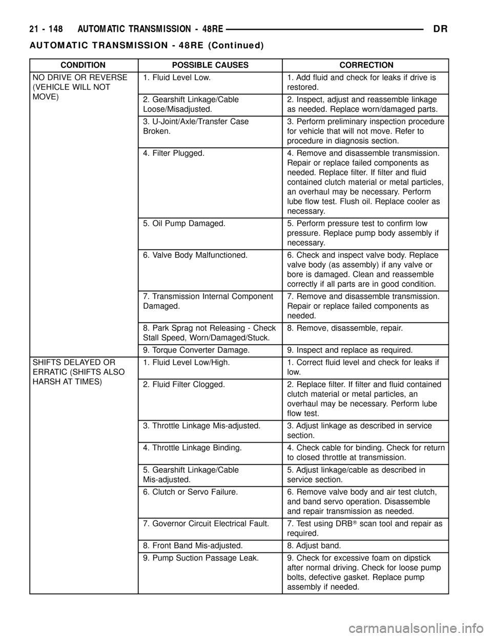
NO DRIVE OR REVERSE
(VEHICLE WILL NOT
MOVE)1. Fluid Level Low. 1. Add fluid and check for leaks if drive is
restored.
2. Gearshift Linkage/Cable
Loose/Misadjusted.2. Inspect, adjust and reassemble linkage
as needed. Replace worn/damaged parts.
3. U-Joint/Axle/Transfer Case
Broken.3. Perform preliminary inspection procedure
for vehicle that will not move. Refer to
procedure in diagnosis section.
4. Filter Plugged. 4. Remove and disassemble transmission.
Repair or replace failed components as
needed. Replace filter. If filter and fluid
contained clutch material or metal particles,
an overhaul may be necessary. Perform
lube flow test. Flush oil. Replace cooler as
necessary.
5. Oil Pump Damaged. 5. Perform pressure test to confirm low
pressure. Replace pump body assembly if
necessary.
6. Valve Body Malfunctioned. 6. Check and inspect valve body. Replace
valve body (as assembly) if any valve or
bore is damaged. Clean and reassemble
correctly if all parts are in good condition.
7. Transmission Internal Component
Damaged.7. Remove and disassemble transmission.
Repair or replace failed components as
needed.
8. Park Sprag not Releasing - Check
Stall Speed, Worn/Damaged/Stuck.8. Remove, disassemble, repair.
9. Torque Converter Damage. 9. Inspect and replace as required.
SHIFTS DELAYED OR
ERRATIC (SHIFTS ALSO
HARSH AT TIMES)1. Fluid Level Low/High. 1. Correct fluid level and check for leaks if
low.
2. Fluid Filter Clogged. 2. Replace filter. If filter and fluid contained
clutch material or metal particles, an
overhaul may be necessary. Perform lube
flow test.
3. Throttle Linkage Mis-adjusted. 3. Adjust linkage as described in service
section.
4. Throttle Linkage Binding. 4. Check cable for binding. Check for return
to closed throttle at transmission.
5. Gearshift Linkage/Cable
Mis-adjusted.5. Adjust linkage/cable as described in
service section.
6. Clutch or Servo Failure. 6. Remove valve body and air test clutch,
and band servo operation. Disassemble
and repair transmission as needed.
7. Governor Circuit Electrical Fault. 7. Test using DRBTscan tool and repair as
required.
8. Front Band Mis-adjusted. 8. Adjust band.
9. Pump Suction Passage Leak. 9. Check for excessive foam on dipstick
after normal driving. Check for loose pump
bolts, defective gasket. Replace pump
assembly if needed.
21 - 148 AUTOMATIC TRANSMISSION - 48REDR
AUTOMATIC TRANSMISSION - 48RE (Continued)
Page 1853 of 2627

CONDITION POSSIBLE CAUSES CORRECTION
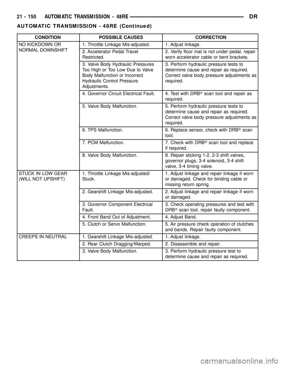
NO KICKDOWN OR
NORMAL DOWNSHIFT1. Throttle Linkage Mis-adjusted. 1. Adjust linkage.
2. Accelerator Pedal Travel
Restricted.2. Verify floor mat is not under pedal, repair
worn accelerator cable or bent brackets.
3. Valve Body Hydraulic Pressures
Too High or Too Low Due to Valve
Body Malfunction or Incorrect
Hydraulic Control Pressure
Adjustments.3. Perform hydraulic pressure tests to
determine cause and repair as required.
Correct valve body pressure adjustments as
required.
4. Governor Circuit Electrical Fault. 4. Test with DRBTscan tool and repair as
required.
5. Valve Body Malfunction. 5. Perform hydraulic pressure tests to
determine cause and repair as required.
Correct valve body pressure adjustments as
required.
6. TPS Malfunction. 6. Replace sensor, check with DRBTscan
tool.
7. PCM Malfunction. 7. Check with DRBTscan tool and replace
if required.
8. Valve Body Malfunction. 8. Repair sticking 1-2, 2-3 shift valves,
governor plugs, 3-4 solenoid, 3-4 shift
valve, 3-4 timing valve.
STUCK IN LOW GEAR
(WILL NOT UPSHIFT)1. Throttle Linkage Mis-adjusted/
Stuck.1. Adjust linkage and repair linkage if worn
or damaged. Check for binding cable or
missing return spring.
2. Gearshift Linkage Mis-adjusted. 2. Adjust linkage and repair linkage if worn
or damaged.
3. Governor Component Electrical
Fault.3. Check operating pressures and test with
DRBTscan tool, repair faulty component.
4. Front Band Out of Adjustment. 4. Adjust Band.
5. Clutch or Servo Malfunction. 5. Air pressure check operation of clutches
and bands. Repair faulty component.
CREEPS IN NEUTRAL 1. Gearshift Linkage Mis-adjusted. 1. Adjust linkage.
2. Rear Clutch Dragging/Warped. 2. Disassemble and repair.
3. Valve Body Malfunction. 3. Perform hydraulic pressure test to
determine cause and repair as required.
21 - 150 AUTOMATIC TRANSMISSION - 48REDR
AUTOMATIC TRANSMISSION - 48RE (Continued)
Page 1864 of 2627

(10) Remove valve body assembly. Push valve body
harness connector out of case. Then work park rod
and valve body out of case (Fig. 20).
(11) Remove accumulator outer spring, piston and
inner spring (Fig. 21). Note position of piston and
springs for assembly reference. Remove and discard
piston seals if worn or cut.
(12) Remove pump oil seal with suitable pry tool
or slide-hammer mounted screw.
(13) Remove front band lever pin access plug (Fig.
22). Use square end of 1/4 in. drive extension to
remove plug as shown.(14) Remove oil pump and reaction shaft support
assembly as follows:
(a) Tighten front band adjusting screw until
band is tight around front clutch retainer (Fig. 23).
This will prevent retainer from coming out with
pump and possibly damaging clutch or pump com-
ponents.
Fig. 23 Tightening Front Band To Hold Front Clutch
In Place
1 - LOCK-NUT
2 - FRONT BAND ADJUSTER
Fig. 20 Valve Body Removal
1 - GOVERNOR PRESSURE SENSOR
2 - VALVE BODY
3 - PARK ROD
4 - ACCUMULATOR PISTON
5 - GOVERNOR PRESSURE SOLENOID
Fig. 21 Accumulator Component Removal
1 - ACCUMULATOR PISTON
2 - OUTER SPRING
3 - INNER SPRING
Fig. 22 Front Band Lever Pin Access Plug
1 - FRONT BAND REACTION PIN ACCESS PLUG
2 - 1/4 DRIVE EXTENSION AND RATCHET
DRAUTOMATIC TRANSMISSION - 48RE 21 - 161
AUTOMATIC TRANSMISSION - 48RE (Continued)
Page 1970 of 2627

TRANSMISSION
TEMPERATURE SENSOR
DESCRIPTION
Transmission fluid temperature readings are sup-
plied to the transmission control module by the ther-
mistor (Fig. 248). The temperature readings are used
to control engagement of the fourth gear overdrive
clutch, the converter clutch, and governor pressure.
Normal resistance value for the thermistor at room
temperature is approximately 2000 ohms.
The thermistor is part of the governor pressure
sensor assembly and is immersed in transmission
fluid at all times.
OPERATION
The PCM prevents engagement of the converter
clutch and overdrive clutch, when fluid temperature
is below approximately 10ÉC (50ÉF).
If fluid temperature exceeds 126ÉC (260ÉF), the
PCM causes a 4-3 downshift and engage the con-
verter clutch. Engagement is according to the third
gear converter clutch engagement schedule.
The Tow/Haul lamp in the instrument panel illumi-
nates when the shift back to third occurs. The trans-
mission will not allow fourth gear operation until
fluid temperature decreases to approximately 110ÉC
(230ÉF).
VALVE BODY
DESCRIPTION
The valve body consists of a cast aluminum valve
body, a separator plate, and transfer plate. The valve
body contains valves and check balls that control
fluid delivery to the torque converter clutch, bands,
and frictional clutches. The valve body contains the
following components (Fig. 249), (Fig. 250), (Fig.
251), and (Fig. 252):
²Regulator valve
²Regulator valve throttle pressure plug
²Line pressure sleeve
²Kickdown valve
²Kickdown limit valve
²1-2 shift valve
²1-2 control valve
²2-3 shift valve
²2-3 governor plug
²3-4 shift valve
²3-4 timing valve
²3-4 quick fill valve
²3-4 accumulator
²Throttle valve
²Throttle pressure plug
²Switch valve
²Manual valve
²Converter clutch lock-up valve
²Converter clutch lock-up timing Valve
²Shuttle valve
²Shuttle valve throttle plug
²Boost Valve
²9 check balls
By adjusting the spring pressure acting on the reg-
ulator valve, transmission line pressure can be
adjusted.
Fig. 248 Governor Pressure Sensor
1 - GOVERNOR BODY
2 - GOVERNOR PRESSURE SENSOR/TRANSMISSION FLUID
TEMPERATURE THERMISTOR
DRAUTOMATIC TRANSMISSION - 48RE 21 - 267
Page 1989 of 2627

BOOST VALVE
The boost valve (Fig. 271) provides increased fluid
apply pressure to the overdrive clutch during 3-4
upshifts (Fig. 272), and when accelerating in fourth
gear. The boost valve also serves to increase line
pressure during torque converter lock-up.
REMOVAL
The valve body can be removed for service without
having to remove the transmission assembly.
The valve body can be disassembled for cleaning
and inspection of the individual components.
The only replaceable valve body components are:
²Manual lever.
²Manual lever washer, seal, E-clip, and shaft
seal.
²Manual lever detent ball.
²Throttle lever.
²Fluid filter.
²Pressure adjusting screw bracket.
²Governor pressure solenoid.
²Governor pressure sensor (includes transmission
temperature thermistor).
²Converter clutch/overdrive solenoid assembly
and harness.
²Governor housing gasket.
²Solenoid case connector O-rings.
(1) Shift transmission into NEUTRAL.
(2) Raise vehicle.
(3) Remove gearshift and throttle levers from shaft
of valve body manual lever.
(4) Disconnect wires at solenoid case connector
(Fig. 273).
(5) Remove the transmission range sensor (Refer
to 21 - TRANSMISSION/AUTOMATIC/TRANSMIS-
SION RANGE SENSOR - REMOVAL).
(6) Position drain pan under transmission oil pan.
(7) Remove transmission oil pan and gasket.
(8) Remove fluid filter from valve body.
(9) Remove bolts attaching valve body to transmis-
sion case.
(10) Lower valve body enough to remove accumu-
lator piston and springs.
Fig. 273 Transmission Case Connector
1 - SOLENOID CASE CONNECTOR
2 - TRANSMISSION RANGE SENSOR
Fig. 271 Boost Valve Before Lock-up
Fig. 272 Boost Valve After Lock-up
21 - 286 AUTOMATIC TRANSMISSION - 48REDR
VALVE BODY (Continued)
Page 1990 of 2627

(11) Work manual lever shaft and electrical con-
nector out of transmission case.
(12) Lower valve body, rotate valve body away
from case, pull park rod out of sprag, and remove
valve body (Fig. 274).
DISASSEMBLY
CAUTION: Do not clamp any valve body component
in a vise. This practice can damage the component
resulting in unsatisfactory operation after assembly
and installation. Do not use pliers to remove any of
the valves, plugs or springs and do not force any of
the components out or into place. The valves and
valve body housings will be damaged if force is
used. Tag or mark the valve body springs for refer-
ence as they are removed. Do not allow them to
become intermixed.
(1) Disconnect wires from governor pressure sen-
sor and solenoid.
(2) Remove screws attaching governor body and
retainer plate to transfer plate.
(3) Remove retainer plate, governor body and gas-
ket from transfer plate.(4) Remove governor pressure sensor from gover-
nor body.
(5) Remove governor pressure solenoid by pulling
it straight out of bore in governor body. Remove and
discard solenoid O-rings if worn, cut, or torn.
(6) Remove small shoulder bolt that secures sole-
noid harness case connector to 3-4 accumulator hous-
ing (Fig. 275). Retain shoulder bolt. Either tape it to
harness or thread it back into accumulator housing
after connector removal.
(7) Unhook overdrive/converter solenoid harness
from 3-4 accumulator cover plate (Fig. 276).
Fig. 275 Solenoid Harness Case Connector
Shoulder Bolt
1 - SOLENOID HARNESS CASE CONNECTOR
2 - 3-4 ACCUMULATOR HOUSING
Fig. 276 Solenoid Harness Routing
1 - OVERDRIVE/CONVERTER SOLENOID WIRE HARNESS
2 - 3-4 ACCUMULATOR COVER PLATE
Fig. 274 Valve Body
1 - VALVE BODY
2 - WIRE HARNESS
3 - PARK ROD
4 - GOVERNOR PRESSURE SOLENOID
5 - GOVERNOR PRESSURE SENSOR
DRAUTOMATIC TRANSMISSION - 48RE 21 - 287
VALVE BODY (Continued)