1998 DODGE RAM 1500 Washer
[x] Cancel search: WasherPage 1402 of 2627
IDLER SHAFT
REMOVAL
(1) Remove the primary and secondary timing
chains and sprockets (Refer to 9 - ENGINE/VALVE
TIMING/TIMING BELT/CHAIN AND SPROCKETS -
REMOVAL).
NOTE: To remove the idler shaft, it is necessary to
tap threads into the shaft, to install the removal
tool.
(2) Using a 12 mm X 1.75 tap, cut threads in the
idler shaft center bore.
(3) Cover the radiator core with a suitable cover.
CAUTION: Use care when removing the idler shaft,
Do not strike the radiator cooling fins with the slide
hammer.
(4) Using Special Tool 8517 Slide Hammer, remove
the idler shaft.
INSTALLATION
(1) Thoroughly clean the idler shaft bore.
(2) Position the idler shaft in the bore.
NOTE: The two lubrication holes in the idler shaft
do not require any special alignment.
NOTE: Before using the retaining bolt to install the
idler shaft, coat the threads and the pilot on the
idler shaft, with clean engine oil.
(3) Using the primary idler sprocket retaining bolt
and washer, carefully draw the idler shaft into the
bore until fully seated.
(4) Coat the idler shaft with clean engine oil.
(5) Install the timing chains and sprockets (Refer
to 9 - ENGINE/VALVE TIMING/TIMING BELT/
CHAIN AND SPROCKETS - INSTALLATION).
DRENGINE - 4.7L 9 - 179
Page 1408 of 2627
DIAGNOSIS AND TESTING - ENGINE DIAGNOSIS - MECHANICAL
CONDITION POSSIBLE CAUSES CORRECTIONS
NOISY VALVES 1. High or low oil level in
crankcase.1. (Refer to LUBRICATION &
MAINTENANCE -
SPECIFICATIONS)
2. Thin or diluted oil. 2. Change oil and filter.
3. Low oil pressure. 3. Check oil pump, if Ok, check rod
and main bearings for excessive
wear.
4. Dirt in lash adjusters. 4. Replace as necessary.
5. Worn rocker arms. 5. Replace as necessary.
6. Worn lash adjusters 6. Replace as necessary.
7. Worn valve guides. 7. (Refer to 9 - ENGINE/CYLINDER
HEAD/INTAKE/EXHAUST VALVES
& SEATS - STANDARD
PROCEDURE)
8. Excessive runout of valve seats
on valve faces.8. (Refer to 9 - ENGINE/CYLINDER
HEAD/INTAKE/EXHAUST VALVES
& SEATS - STANDARD
PROCEDURE)
CONNECTING ROD NOISE 1. Insufficient oil supply. 1. (Refer to LUBRICATION &
MAINTENANCE -
SPECIFICATIONS)
2. Low oil pressure. 2. Check oil pump, if Ok, check rod
and main bearings for excessive
wear.
3. Thin or diluted oil. 3. Change oil and filter.
4. Excessive bearing clearance. 4. Replace as necessary.
5. Connecting rod journal
out-of-round.5. Service or replace crankshaft.
6. Misaligned connecting rods. 6. Replace bent connecting rods.
MAIN BEARING NOISE 1. Insufficient oil supply. 1. (Refer to LUBRICATION &
MAINTENANCE -
SPECIFICATIONS)
2. Low oil pressure. 2. Check oil pump, if Ok, check rod
and main bearings for excessive
wear.
3. Thin or diluted oil. 3. Change oil and filter.
4. Excessive bearing clearance. 4. Replace as necessary.
5. Excessive end play. 5. Check thrust washers for wear.
6. Crankshaft journal out-of round. 6. Service or replace crankshaft.
7. Loose flywheel or torque
converter.7. Tighten to correct torque
DRENGINE - 5.7L 9 - 185
ENGINE - 5.7L (Continued)
Page 1414 of 2627
(6) Remove the viscous fan/drive (Refer to 7 -
COOLING/ENGINE/RADIATOR FAN - REMOVAL).
(7) Remove radiator (Refer to 7 - COOLING/EN-
GINE/RADIATOR - REMOVAL).
(8) Remove the upper crossmember and top core
support.
NOTE: It is not necessary to drain A/C system for
engine removal.
(9) Remove the A/C compressor with the lines
attached. Secure compressor out of the way.
(10) Remove generator assembly (Refer to 8 -
ELECTRICAL/CHARGING/GENERATOR -
REMOVAL).
(11) Remove the intake manifold and IAFM as an
assembly(Refer to 9 - ENGINE/MANIFOLDS/IN-
TAKE MANIFOLD - REMOVAL).
(12) Disconnect the heater hoses.
NOTE: It is not necessary to disconnect P/S hoses
from pump, for P/S pump removal.
(13) Remove the power steering pump and set
aside.
(14) Disconnect the fuel supply line (Refer to 14 -
FUEL SYSTEM/FUEL DELIVERY/QUICK CON-
NECT FITTING - STANDARD PROCEDURE).
(15) Raise and support the vehicle on a hoist and
drain the engine oil.
(16) Remove engine front mount thru-bolt nuts.
(17) Remove right side axle retaining bolts.
(18) Disconnect the transmission oil cooler lines
from their retainers at the oil pan bolts.
(19) Disconnect exhaust pipe at manifolds.
(20) Disconnect the starter wires. Remove starter
motor (Refer to 8 - ELECTRICAL/STARTING/
STARTER MOTOR - REMOVAL).
(21) Remove the structural dust cover and trans-
mission inspection cover,(Refer to 9 - ENGINE/EN-
GINE BLOCK/STRUCTURAL COVER - REMOVAL).
(22) Remove drive plate to converter bolts (Auto-
matic transmission equipped vehicles).
(23) Remove transmission bell housing to engine
block bolts.
(24) Lower the vehicle.
(25) Install engine lift fixture, special tool # 8984.
(26) Separate engine from transmission, remove
engine from vehicle, and install engine assembly on a
repair stand.
INSTALLATION
(1) Install engine lift fixture Special tool # 8984.
(2) Position the engine in the engine compartment.
(3) Lower engine into compartment and align
engine with transmission:²Manual Transmission: Align clutch disc assem-
bly (if disturbed). Install transmission input shaft
into clutch disc while mating engine and transmis-
sion surfaces. Install two transmission to engine
block mounting bolts finger tight.
²Automatic Transmission: Mate engine and trans-
mission and install two transmission to engine block
mounting bolts finger tight.
(4) Position the thru-bolt into the support cushion
brackets.
(5) Lower engine assembly until engine mount
through bolts rest in mount perches.
(6) Install remaining transmission to engine block
mounting bolts and tighten.
(7) Tighten engine mount through bolts.
(8) Install drive plate to torque converter bolts.
(Automatic transmission models)
(9) Install the structural dust cover and transmis-
sion dust cover,(Refer to 9 - ENGINE/ENGINE
BLOCK/STRUCTURAL COVER - INSTALLATION).
(10) Install the starter and connect the starter
wires (Refer to 8 - ELECTRICAL/STARTING/
STARTER MOTOR - INSTALLATION).
(11) Install exhaust pipe to manifold.
(12) Lower the vehicle.
(13) Remove engine lift fixture, special tool # 8984.
(14) Connect the fuel supply line (Refer to 14 -
FUEL SYSTEM/FUEL DELIVERY/QUICK CON-
NECT FITTING - STANDARD PROCEDURE).
(15) Reinstall the power steering pump.
(16) Connect the heater hoses.
(17) Install the intake manifold.
(18) Using a new gasket, install throttle body
(Refer to 14 - FUEL SYSTEM/FUEL INJECTION/
THROTTLE BODY - INSTALLATION).
(19) Install the generator and wire connections
(Refer to 8 - ELECTRICAL/CHARGING/GENERA-
TOR - INSTALLATION).
(20) Install a/c compressor and lines (Refer to 24 -
HEATING & AIR CONDITIONING/PLUMBING/A/C
COMPRESSOR - INSTALLATION).
(21) Install the accessory drive belt (Refer to 7 -
COOLING/ACCESSORY DRIVE/DRIVE BELTS -
INSTALLATION).
(22) Install upper radiator support crossmember.
(23) Install radiator (Refer to 7 - COOLING/EN-
GINE/RADIATOR - INSTALLATION).
(24) Connect the radiator lower hose.
(25) Connect the transmission oil cooler lines to
the radiator.
(26) Install the fan shroud.
(27) Install the fan (Refer to 7 - COOLING/EN-
GINE/RADIATOR FAN - INSTALLATION).
(28) Connect the radiator upper hose.
(29) Install the washer bottle.
(30) Connect the transmission cooler lines.
DRENGINE - 5.7L 9 - 191
ENGINE - 5.7L (Continued)
Page 1430 of 2627
(10) Remove the thrust washers.
(11) Remove the rear oil seal retainer(Refer to 9 -
ENGINE/ENGINE BLOCK/CRANKSHAFT REAR
OIL SEAL RETAINE - REMOVAL).
(12) Remove the crankshaft out of the block.
(13) Remove and discard the crankshaft rear oil
seal.
(14) Remove and discard the front crankshaft oil
seal.
INSTALLATION
(1) Select the proper main bearings(Refer to 9 -
ENGINE/ENGINE BLOCK/CRANKSHAFT MAIN
BEARINGS - STANDARD PROCEDURE) .
(2) Install main bearings in block and caps, and
lubricate bearings.
(3) Position the crankshaft into the cylinder block.
(4) Install the thrust washers.
NOTE: The main cap crossbolts are torqued after
final torque of the main cap bolts. Always use a
new washer/seal on crossbolts.
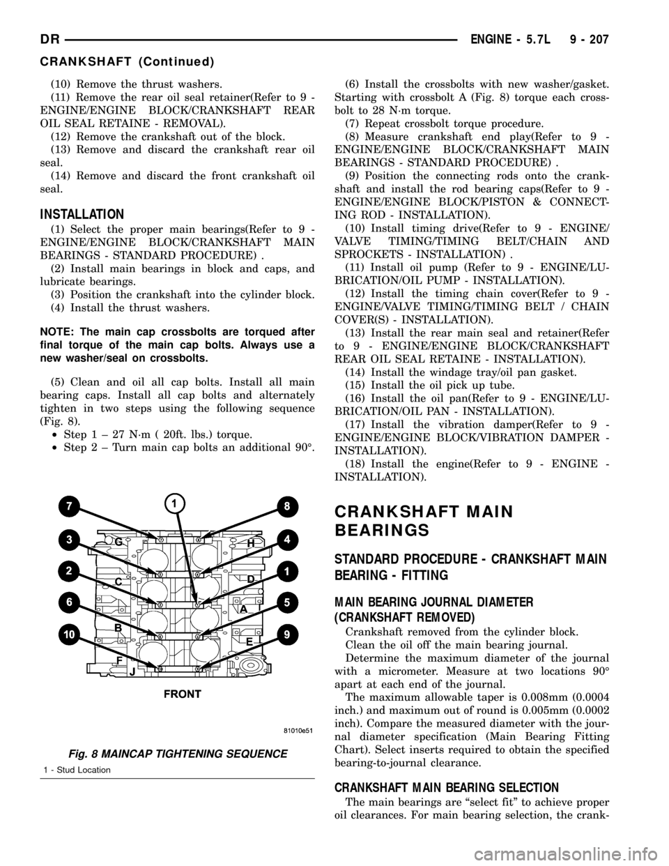
(5) Clean and oil all cap bolts. Install all main
bearing caps. Install all cap bolts and alternately
tighten in two steps using the following sequence
(Fig. 8).
²Step1±27N´m(20ft. lbs.) torque.
²Step2±Turnmain cap bolts an additional 90É.(6) Install the crossbolts with new washer/gasket.
Starting with crossbolt A (Fig. 8) torque each cross-
bolt to 28 N´m torque.
(7) Repeat crossbolt torque procedure.
(8) Measure crankshaft end play(Refer to 9 -
ENGINE/ENGINE BLOCK/CRANKSHAFT MAIN
BEARINGS - STANDARD PROCEDURE) .
(9) Position the connecting rods onto the crank-
shaft and install the rod bearing caps(Refer to 9 -
ENGINE/ENGINE BLOCK/PISTON & CONNECT-
ING ROD - INSTALLATION).
(10) Install timing drive(Refer to 9 - ENGINE/
VALVE TIMING/TIMING BELT/CHAIN AND
SPROCKETS - INSTALLATION) .
(11) Install oil pump (Refer to 9 - ENGINE/LU-
BRICATION/OIL PUMP - INSTALLATION).
(12) Install the timing chain cover(Refer to 9 -
ENGINE/VALVE TIMING/TIMING BELT / CHAIN
COVER(S) - INSTALLATION).
(13) Install the rear main seal and retainer(Refer
to 9 - ENGINE/ENGINE BLOCK/CRANKSHAFT
REAR OIL SEAL RETAINE - INSTALLATION).
(14) Install the windage tray/oil pan gasket.
(15) Install the oil pick up tube.
(16) Install the oil pan(Refer to 9 - ENGINE/LU-
BRICATION/OIL PAN - INSTALLATION).
(17) Install the vibration damper(Refer to 9 -
ENGINE/ENGINE BLOCK/VIBRATION DAMPER -
INSTALLATION).
(18) Install the engine(Refer to 9 - ENGINE -
INSTALLATION).
CRANKSHAFT MAIN
BEARINGS
STANDARD PROCEDURE - CRANKSHAFT MAIN
BEARING - FITTING
MAIN BEARING JOURNAL DIAMETER
(CRANKSHAFT REMOVED)
Crankshaft removed from the cylinder block.
Clean the oil off the main bearing journal.
Determine the maximum diameter of the journal
with a micrometer. Measure at two locations 90É
apart at each end of the journal.
The maximum allowable taper is 0.008mm (0.0004
inch.) and maximum out of round is 0.005mm (0.0002
inch). Compare the measured diameter with the jour-
nal diameter specification (Main Bearing Fitting
Chart). Select inserts required to obtain the specified
bearing-to-journal clearance.
CRANKSHAFT MAIN BEARING SELECTION
The main bearings are ªselect fitº to achieve proper
oil clearances. For main bearing selection, the crank-
Fig. 8 MAINCAP TIGHTENING SEQUENCE
1 - Stud Location
DRENGINE - 5.7L 9 - 207
CRANKSHAFT (Continued)
Page 1438 of 2627
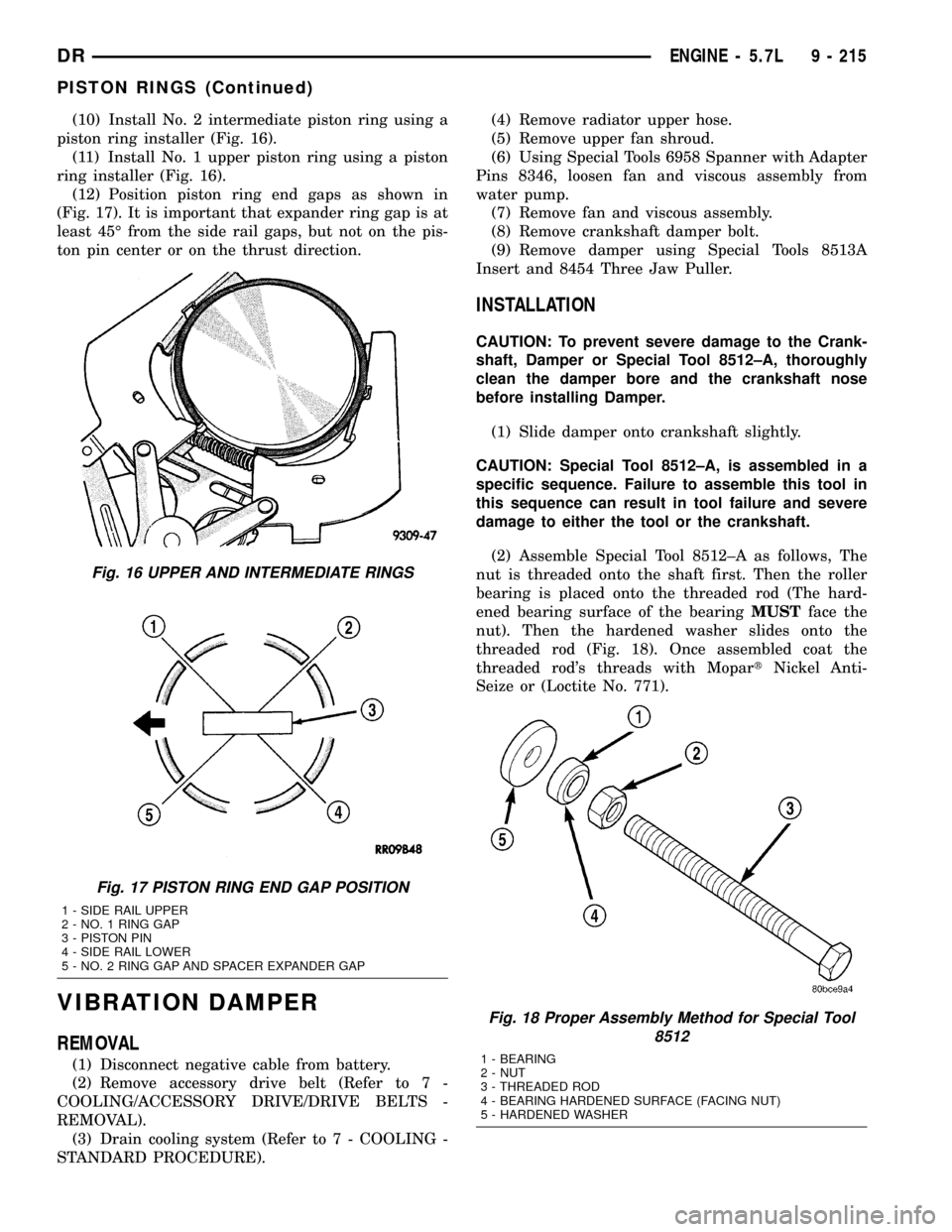
(10) Install No. 2 intermediate piston ring using a
piston ring installer (Fig. 16).
(11) Install No. 1 upper piston ring using a piston
ring installer (Fig. 16).
(12) Position piston ring end gaps as shown in
(Fig. 17). It is important that expander ring gap is at
least 45É from the side rail gaps, but not on the pis-
ton pin center or on the thrust direction.
VIBRATION DAMPER
REMOVAL
(1) Disconnect negative cable from battery.
(2) Remove accessory drive belt (Refer to 7 -
COOLING/ACCESSORY DRIVE/DRIVE BELTS -
REMOVAL).
(3) Drain cooling system (Refer to 7 - COOLING -
STANDARD PROCEDURE).(4) Remove radiator upper hose.
(5) Remove upper fan shroud.
(6) Using Special Tools 6958 Spanner with Adapter
Pins 8346, loosen fan and viscous assembly from
water pump.
(7) Remove fan and viscous assembly.
(8) Remove crankshaft damper bolt.
(9) Remove damper using Special Tools 8513A
Insert and 8454 Three Jaw Puller.
INSTALLATION
CAUTION: To prevent severe damage to the Crank-
shaft, Damper or Special Tool 8512±A, thoroughly
clean the damper bore and the crankshaft nose
before installing Damper.
(1) Slide damper onto crankshaft slightly.
CAUTION: Special Tool 8512±A, is assembled in a
specific sequence. Failure to assemble this tool in
this sequence can result in tool failure and severe
damage to either the tool or the crankshaft.
(2) Assemble Special Tool 8512±A as follows, The
nut is threaded onto the shaft first. Then the roller
bearing is placed onto the threaded rod (The hard-
ened bearing surface of the bearingMUSTface the
nut). Then the hardened washer slides onto the
threaded rod (Fig. 18). Once assembled coat the
threaded rod's threads with MopartNickel Anti-
Seize or (Loctite No. 771).
Fig. 16 UPPER AND INTERMEDIATE RINGS
Fig. 17 PISTON RING END GAP POSITION
1 - SIDE RAIL UPPER
2 - NO. 1 RING GAP
3 - PISTON PIN
4 - SIDE RAIL LOWER
5 - NO. 2 RING GAP AND SPACER EXPANDER GAP
Fig. 18 Proper Assembly Method for Special Tool
8512
1 - BEARING
2 - NUT
3 - THREADED ROD
4 - BEARING HARDENED SURFACE (FACING NUT)
5 - HARDENED WASHER
DRENGINE - 5.7L 9 - 215
PISTON RINGS (Continued)
Page 1450 of 2627
INSPECTION
Inspect manifold for cracks.
Inspect mating surfaces of manifold for flatness
with a straight edge. Gasket surfaces must be flat
within 0.2 mm per 300 mm (0.008 inch per foot).
INSTALLATION
EXHAUST MANIFOLD
(1) Install manifold gasket and manifold.
(2) Install manifold bolts and tighten to 25 N´m
(18 ft. lbs.).
(3) Install heat shield and tighten nuts to 15 N´m
(11 ft. lbs.).
(4) Lower engine.
CAUTION: Do not damage engine harness while
lowering the engine.
(5) Remove engine support fixture from engine.
(6) Raise vehicle.
(7) Tighten right and left side engine mount
through bolts.
(8) Install exhaust flange to pipe bolts.
(9) Lower vehicle.
(10) Connect negative battery cable.
TIMING/CHAIN COVER
REMOVAL
(1) Disconnect the battery negative cable.
(2) Remove air cleaner assembly.
(3) Drain cooling system.
(4) Remove accessory drive belt.
(5) Remove fan and fan drive assembly (Refer to 7
- COOLING/ENGINE/FAN DRIVE VISCOUS
CLUTCH - REMOVAL).
(6) Remove coolant bottle and washer bottle.
(7) Remove fan shroud.
NOTE: It is not necessary to disconnect A/C lines or
discharge freon.
(8) Remove A/C compressor and set aside.
(9) Remove the generator.
(10) Remove upper radiator hose.
(11) Disconnect both heater hoses at timing cover.
(12) Disconnect lower radiator hose at engine.
(13) Remove accessory drive belt tensioner and
both idler pulleys.
(14) Remove crankshaft damper(Refer to 9 -
ENGINE/ENGINE BLOCK/VIBRATION DAMPER -
REMOVAL).NOTE: Do not remove the hoses from the power
steering pump.
(15) Remove power steering pump and set aside.
(16) Remove the dipstick support bolt.
(17) Drain the engine oil.
(18) Remove the oil pan and pick up tube(Refer to
9 - ENGINE/LUBRICATION/OIL PAN - REMOVAL).
NOTE: It is not necessary to remove water pump for
timing cover removal.
(19) Remove timing cover bolts and remove cover.
INSTALLATION
(1) Clean timing chain cover and block surface.
NOTE: Always install a new gasket on timing cover.
(2) Install cover and new gasket. Tighten fasteners
to 28 N´m (250 in. lbs.).
NOTE: The large lifting stud is torqued to 55 N´m
(40 ft. lbs.).
(3) Install the oil pan and pick up tube(Refer to 9 -
ENGINE/LUBRICATION/OIL PAN - INSTALLA-
TION).
(4) Install the A/C compressor.
(5) Install the generator.
(6) Install power steering pump.
(7) Install the dipstick support bolt.
(8) Install the thermostat housing.
(9) Install crankshaft damper(Refer to 9 -
ENGINE/ENGINE BLOCK/VIBRATION DAMPER -
INSTALLATION).
(10) Install accessory drive belt tensioner assembly
and both idler pulleys.
(11) Install radiator lower hose.
(12) Install both heater hoses.
(13) Install radiator fan shroud.
(14) Install the fan and fan drive assembly
(15) Install the accessory drive belt.
(16) Install the coolant bottle and washer bottle.
(17) Install the upper radiator hose.
(18) Install the air cleaner assembly.
(19) Fill cooling system.
(20) Refill engine oil.
(21) Connect the battery negative cable.
DRENGINE - 5.7L 9 - 227
EXHAUST MANIFOLD (Continued)
Page 1460 of 2627
EXCESSIVE WHITE SMOKE
POSSIBLE CAUSE CORRECTION
Air in fuel supply: Possible leak in fuel supply side (between
transfer pump and fuel tank module).(Refer to 14 - FUEL SYSTEM/FUEL DELIVERY/FUEL
TRANSFER PUMP - DIAGNOSIS AND TESTING).
Coolant leaking into combustion chamber. Do pressure test of cooling system (Refer to 7 - COOLING -
DIAGNOSIS AND TESTING).
Diagnostic Trouble Codes (DTC's) active or multiple,
intermittent DTC's.Refer to Powertrain Diagnostic Procedures Information.
In very cold ambient temperatures, engine block heater is
malfunctioning (if equipped).(Refer to 7 - COOLING/ENGINE/ENGINE BLOCK HEATER -
REMOVAL).
Engine coolant temperature sensor malfunctioning. A DTC should have been set. Refer to Powertrain Diagnostic
Procedures Information. Also check thermostat operation
(Refer to 7 - COOLING/ENGINE/ENGINE COOLANT
THERMOSTAT - DIAGNOSIS AND TESTING).
Engine Control Module (ECM) not calibrated or has incorrect
calibration.A DTC should have been set. Refer to Powertrain Diagnostic
Procedures Information.
Fuel filter plugged. Refer to Powertrain Diagnostic Manual for fuel system testing.
Fuel grade not correct or fuel quality is poor. Temporarily change fuel brands and note condition. Change
brand if necessary.
Fuel heater element or fuel heater temperature sensor
malfunctioning. This will cause wax type build-up in fuel filter.Refer to Fuel Heater Testing (Refer to 14 - FUEL SYSTEM/
FUEL DELIVERY/FUEL HEATER - DIAGNOSIS AND
TESTING).
Fuel injector malfunctioning. A DTC should have been set. Perform9Cylinder cutout Test9
using DRB scan tool to isolate individual cylinders. Also refer
to Powertrain Diagnostic Procedures Information and, (Refer
to 14 - FUEL SYSTEM/FUEL INJECTION/FUEL INJECTOR -
DIAGNOSIS AND TESTING).
Fuel injector hold-downs loose. Torque to specifications.
Fuel injector protrusion not correct. Check washer (shim) at bottom of fuel injector for correct
thickness. (Refer to 14 - FUEL SYSTEM/FUEL INJECTION/
FUEL INJECTOR - INSTALLATION)
Fuel injection pump malfunctioning. A DTC should have been set. Refer to Powertrain Diagnostic
Procedures Information.
Fuel supply side restriction to transfer pump. Refer to Powertrain Diagnostic Manual for fuel system testing.
Fuel transfer (lift) pump malfunctioning. A DTC may have been set. Refer to Powertrain Diagnostic
Procedures Information.
Intake/Exhaust valve adjustments not correct (too tight). (Refer to 9 - ENGINE/CYLINDER HEAD/INTAKE/EXHAUST
VALVES & SEATS - STANDARD PROCEDURE).
Intake manifold air temperature sensor malfunctioning. A DTC should have been set. Refer to Powertrain Diagnostic
Procedures Information.
Intake manifold heater circuit not functioning correctly in cold
weather.A DTC should have been set. Refer to Powertrain Diagnostic
Procedures Information. Also check heater elements for
correct operation.
Intake manifold heater elements not functioning correctly in
cold weather.A DTC should have been set if heater elements are
malfunctioning. Refer to Powertrain Diagnostic Procedures
Information.
Internal engine damage (scuffed cylinder). Analyze engine oil and inspect oil filter to locate area of
probable damage.
Restriction in fuel supply side of fuel system. Refer to Powertrain Diagnostic Manual for fuel system testing.
DRENGINE 5.9L DIESEL 9 - 237
ENGINE 5.9L DIESEL (Continued)
Page 1462 of 2627
DIAGNOSIS AND TESTING - CYLINDER
COMPRESSION/LEAKAGE TESTS
CYLINDER COMPRESSION PRESSURE
The results of a cylinder compression pressure test
can be utilized to diagnose several engine malfunc-
tions.
Ensure batteries are completely charged and the
engine starter motor is in good operating condition.
Otherwise, the indicated compression pressures may
not be valid for diagnostic purposes.
(1) Disconnect the fuel inlet line to the fuel trans-
fer pump. Plug the fuel line from the fuel tank.
(2) Start the engine and idle until the engine stalls
(runs out of fuel).
(3) Disconnect all three injector wire harness con-
nectors at the rocker housing.
(4) Remove the breather cover and cylinder head
cover.
(5) Remove the high pressure fuel line between the
cylinder head and fuel rail for the cylinder to be
tested. Use tool# 9011 to cap this fuel rail on the cyl-
inder being tested.
(6) Remove the exhaust rocker lever.
(7) Use Tool 9010 to remove the injector and cop-
per sealing washer.
(8) Install the exhaust rocker lever and torque to
36 N´m (27 ft. lbs.).
(9) Cover the remaining rocker levers with clean
shop towels to prevent any oil splatter under the
hood.
(10) Place a rag over the compression test tool fit-
ting. Crank the engine for 2±3 seconds to purge any
fuel that may have drained into the cylinder when
the injector was removed.
(11) Connect the compression test gauge.
(12) Crank the engine for 5 seconds and record the
pressure reading. Repeat this step three times and
calculate the average of the three readings.
NOTE: The minimum cylinder pressure is 350 psi.
Cylinder pressure should be within 20% from cylin-
der to cylinder.
(13) Combustion pressure leakage can be checked
if cylinder pressure is below the specification. Per-
form the leakage test procedure on each cylinder
according to the tester manufacturer instructions.
(14) Upon completion of the test check an erase
any engine related fault codes.
CYLINDER COMBUSTION PRESSURE LEAKAGE
The combustion pressure leakage test provides an
accurate means for determining engine condition.
Combustion pressure leakage testing will detect:²Exhaust and intake valve leaks (improper seat-
ing).
²Leaks between adjacent cylinders or into water
jacket.
²Any causes for combustion/compression pressure
loss
(1) Start and operate the engine until it attains
normal operating temperature.
(2) Remove the breather cover and cylinder head
cover.
(3) Disconnect all three injector wire harness con-
nectors at the rocker housing.
(4) Bring the cylinder to be tested to TDC.
(5) Remove the high pressure fuel line between the
cylinder head and the fuel rail for the cylinder to be
tested.
(6) Install capping Tool 9011 onto the rail.
(7) Remove the high pressure connector nut and
high pressure connector with Tool 9015.
(8) Remove the exhaust and intake rocker lever.
(9) Use Tool 9010 to remove the injector and cop-
per sealing washer.
(10) Install compression test Tool 9007 into the
injector bore.
(11) Connect the leakage tester and perform the
leakage test procedure on each cylinder according to
the tester manufacturer's instructions.
(12) Upon completion of the test check and erase
any engine related fault codes.
STANDARD PROCEDURE
STANDARD PROCEDURE - FORM-IN-PLACE
GASKETS AND SEALERS
There are numerous places where form-in-place
gaskets are used on the engine. Care must be taken
when applying form-in-place gaskets to assure
obtaining the desired results.Do not use form-in-
place gasket material unless specified.Bead size,
continuity, and location are of great importance. Too
thin a bead can result in leakage while too much can
result in spill-over which can break off and obstruct
fluid feed lines. A continuous bead of the proper
width is essential to obtain a leak-free gasket.
There are numerous types of form-in-place gasket
materials that are used in the engine area. Mopart
Engine RTV GEN II, MopartATF-RTV, and Mopart
Gasket Maker gasket materials, each have different
properties and can not be used in place of the other.
MOPARtENGINE RTV GEN II
MopartEngine RTV GEN II is used to seal com-
ponents exposed to engine oil. This material is a spe-
cially designed black silicone rubber RTV that
retains adhesion and sealing properties when
exposed to engine oil. Moisture in the air causes the
DRENGINE 5.9L DIESEL 9 - 239
ENGINE 5.9L DIESEL (Continued)