1998 DODGE RAM 1500 Washer
[x] Cancel search: WasherPage 1466 of 2627
(8) Replace injector o-ring and sealing washer on
injectors #5 and #6. Install injectors and torque using
the following steps:
²Step 1ÐInstall injector hold-down capscrews
and torque to 5 N´m (44 in. lbs.) torque.
²Step 2ÐLoosen injector hold-down capscrews.
²Step 3ÐInstall HPC connector tube and nut.
Torque nut to 15 N´m (11 ft. lbs.) torque.
²Step 4ÐTorque injector hold-down capscrews to
10 N´m (89 in. lbs.) torque.
²Step 5ÐTorque HPC connector tube nut to 50
N´m (37 ft. lbs.) torque.
(9) Install #5 and #6 high pressure fuel lines. Fol-
low correct torque sequence per section 14. Torque
fuel line fittings to 30 N-m (22 ft-lb). Torque brace
capscrew to 24 N-m (18 ft-lb).
(10) Install rear engine lift bracket. Torque to 77
N-m (57 ft-lb).
(11) Install push tubes, rocker arms, and pedestals
for cylinders #4, #5, and #6. Torque the mounting
bolts to 36 N-m (27 ft-lbs).
(12) Reset valve lash on cylinders #4, #5, and #6.
Torque adjusting nuts to 24 N-m (18 ft-lbs).
(13) Install cylinder head cover. Torque to 24 N-m
(18 ft-lbs).(Refer to 9 - ENGINE/CYLINDER HEAD -
INSTALLATION).
(14) Connect breather tube and lube oil drain tube
to breather housing cover. Install breather housing.
Torque capscrews to 24 N-m (18 ft-lbs)
(15) Connect fuel supply and return hoses.
(16) Connect ECM ground to hydroform screw.
Connect ECM power connector.
(17) Install the APPS cable(s) to the APPS. Install
the throttle linkage cover.
(18) Install the power steering pump.
(19) Install the damper and speed indicator ring.
Torque to 40 N-m (30 ft-lb) plus 60 degrees.
(20) Connect the engine block heater connection.
(21) Connect the A/C compressor and pressure sen-
sor connectors
(22) Install the charge air cooler and a/c condenser
(if equipped). Install and tighten the charge air
cooler mounting bolts to 2 N-m (17 in-lbs).
(23) Connect the charge air cooler piping. Torque
all clamps to 8 N-m (72 in-lbs).
(24) Connect the a/c refrigerant lines to the a/c
condenser (if equipped).
(25) Install the radiator upper support panel.
(26) Install radiator.
(27) Connect the transmission quick-connect oil
cooler lines.(28) Raise vehicle.
(29) Connect a/c compressor suction/discharge hose
(if equipped).
(30) Install the radiator lower hose and clamps.
(31) Install the battery negative cables to the
engine block on the driver and passenger side.
(32) Install the transmission adapter with a new
camshaft rectangular ring seal. Torque to 77 N-m (57
ft-lb).
(33) Install the flywheel/flexplate. Torque to 137
N-m (101 ft-lb).
(34) Install the starter motor. Torque to 43 N-m
(32 ft-lb). (Refer to 8 - ELECTRICAL/STARTING/
STARTER MOTOR - INSTALLATION).
(35) Connect engine to vehicle harness connectors.
(36) Install transmission and transfer case (if
equipped).
(37) Connect the exhaust pipe to the turbocharger
elbow.
(38) Connect the transmission auxiliary oil cooler
lines (if equipped).
(39) Lower the vehicle.
(40) Connect the heater core supply and return
hoses.
(41) Install the cooling fan and upper fan shroud
at the same time. (Refer to 7 - COOLING/ENGINE/
RADIATOR FAN - INSTALLATION).
(42) Install the coolant recovery bottle.
(43) Install the windshield washer bottle.
(44) Install the upper radiator hose and clamps.
(45) Raise vehicle.
(46) Connect electronically controlled fan drive
wire harness. Install lower radiator fan shroud.
(47) Change oil filter and install new engine oil.
(48) Fill the cooling system with coolant. (Refer to
7 - COOLING - STANDARD PROCEDURE).
(49) Connect grid heater harness at grid heater
relays.
(50) Connect electrical connections to rear of alter-
nator.
(51) Start the engine and inspect for engine oil,
coolant, and fuel leaks.
INSTALLATIONÐCRANKCASE BREATHER
(1) Install a new o-ring onto the breather element.
(2) Lubricate o-ring and install into cylinder head
cover. Torque capscrews to 10 N´m (89 in. lbs.).
(3) Connect breather tube and lube oil drain tube.
(4) Install breather cover (Fig. 4). Torque to 24
N´m (18 ft. lbs.)
(5) Install oil fill cap.
DRENGINE 5.9L DIESEL 9 - 243
ENGINE 5.9L DIESEL (Continued)
Page 1474 of 2627
(32) Disconnect fuel heater, water in fuel sensor,
and fuel lift pump connectors.
(33) Remove the fuel filter assembly-to-cylinder
head bolts and remove filter assembly from vehicle.
(34) Remove wire harness P-clip from cylinder
head (located behind filter housing).
(35) Remove the cylinder head cover(Refer to 9 -
ENGINE/CYLINDER HEAD/CYLINDER HEAD
COVER(S) - REMOVAL).
(36) Disconnect rocker housing injector harness
connectors.
(37) Remove injector harness nuts from injectors.
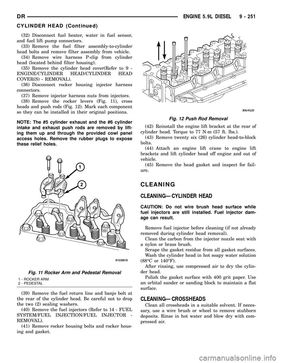
(38) Remove the rocker levers (Fig. 11), cross
heads and push rods (Fig. 12). Mark each component
so they can be installed in their original positions.
NOTE: The #5 cylinder exhaust and the #6 cylinder
intake and exhaust push rods are removed by lift-
ing them up and through the provided cowl panel
access holes. Remove the rubber plugs to expose
these relief holes.
(39) Remove the fuel return line and banjo bolt at
the rear of the cylinder head. Be careful not to drop
the two (2) sealing washers.
(40) Remove the fuel injectors (Refer to 14 - FUEL
SYSTEM/FUEL INJECTION/FUEL INJECTOR -
REMOVAL).
(41) Remove rocker housing bolts and rocker hous-
ing and gasket.(42) Reinstall the engine lift bracket at the rear of
cylinder head. Torque to 77 N´m (57 ft. lbs.).
(43) Remove twenty six (26) cylinder head-to-block
bolts.
(44) Attach an engine lift crane to engine lift
brackets and lift cylinder head off engine and out of
vehicle.
(45) Remove the head gasket and inspect for fail-
ure.
CLEANING
CLEANINGÐCYLINDER HEAD
CAUTION: Do not wire brush head surface while
fuel injectors are still installed. Fuel injector dam-
age can result.
Remove fuel injector before cleaning (if not already
removed during cylinder head removal).
Clean the carbon from the injector nozzle seat with
a nylon or brass brush.
Scrape the gasket residue from all gasket surfaces.
Wash the cylinder head in hot soapy water solution
(88ÉC or 140ÉF).
After rinsing, use compressed air to dry the cylin-
der head.
Polish the gasket surface with 400 grit paper. Use
an orbital sander or sanding block to maintain a flat
surface.
CLEANINGÐCROSSHEADS
Clean all crossheads in a suitable solvent. If neces-
sary, use a wire brush or wheel to remove stubborn
deposits. Rinse in hot water and blow dry with com-
pressed air.
Fig. 11 Rocker Arm and Pedestal Removal
1 - ROCKER ARM
2 - PEDESTAL
Fig. 12 Push Rod Removal
DRENGINE 5.9L DIESEL 9 - 251
CYLINDER HEAD (Continued)
Page 1477 of 2627
(9) Install rocker housing and bolts. Tighten to 24
Nm (18 lb. ft.).
(10) Install fuel injector(Refer to 14 - FUEL SYS-
TEM/FUEL INJECTION/FUEL INJECTOR -
INSTALLATION).
(11) Install injector harness nuts. Tighten to 1.25
Nm (11 lb. in.).
(12) Install cylinder head cover (Refer to 9 -
ENGINE/CYLINDER HEAD/CYLINDER HEAD
COVER(S) - INSTALLATION).
(13) Install wire harness P-clip to cylinder head
behind filter housing 24 N´m (18 ft. lbs.).
(14) Connect the IAT/MAP sensor connector.
(15) Install the fuel filter canister assembly and
torque mounting bolts to 24 N´m (18 ft. lbs.).
(16) Connect fuel lift pump, WIF sensor, and fuel
heater.
(17) Remove the engine lift bracket at rear of cyl-
inder head.
CAUTION: Failure to follow procedure will result in
fuel leaks and/or fuel system failure.
(18)Install the fuel rail and high pressure
fuel lines as follows:
(a) Hand tighten fuel rail bolts.
(b) Hand tighten fuel drain line to pressure lim-
iting valve. Hand tighten banjo bolt at fuel filter
housing.
(c) Hand tighten fuel rail-to-cylinder head high
pressure fuel lines.(d) Install fuel line brace bolts-to-intake mani-
fold finger tight.
(e) Hand tighten fuel pump to fuel rail line.
(f) Torque fuel line nuts at cylinder head to 30
Nm ( 22 ft. lbs.).
(g) Torque fuel line nuts at fuel rail to 30 Nm
(22 ft. lbs.)
(h) Using a back up wrench, torque fuel pump to
fuel rail line to 37 Nm (27 ft. lbs.). At injection
pump.
(i) Torque fuel pump to fuel rail line to 37 Nm
(27 ft. lbs.) at fuel rail.
(j) Torque fuel drain banjo bolt at pressure lim-
iting valve and front of fuel filter housing to 24 Nm
(18 ft. lbs.).
(k) Torque fuel line brace bolts to 24 N´m (18 ft.
lbs.).
(l) Torque rail bolts to 24 Nm (18 ft. lbs.).
(m) Connect fuel pressure sensor.
(19) Install the engine lift bracket at the rear of
cylinder head. Torque to 77 N´m (57 ft. lbs.).
(20) Reposition number 6 fuel line shield and
torque to 43 N´m (32 ft. lbs.).
(21) Install the fuel filter to injection pump low
pressure line. Inspect and replace sealing washers if
necessary. Torque banjo bolts to 24 N´m (18 ft. lbs.).
(22) Connect fuel return line at back of cylinder
head hand tight.
(23) Connect fuel return line at filter housing hand
tight.
(24) Torque banjo connections at cylinder head and
fuel filter housing to 24 Nm (18 ft. lbs.)
(25) Install bracket to rear of filter housing.
Torque to 24 Nm (18 ft. lbs.).
(26) Using new gaskets, install the intake grid
heater and air inlet housing. Torque bolts to 24 N´m
(18 ft. lbs.).
(27) Install wire harness P-clip and push on clip to
air inlet housing.
(28) Connect engine oil level indicator tube at fuel
filter housing and at air inlet housing.
(29) Connect the APPS connector.
(30) Install the APPS assembly to the cylinder
head bracket and torque bolts to 24 N´m (18 ft. lbs.).
(31) Install the throttle linkage cover.
(32) Install the charge air cooler-to-air inlet hous-
ing duct assembly. Torque all clamps to 11 N´m (100
in. lbs.).
(33) Connect intake grid heater wires.
(34) Secure engine harness to front of cylinder
head with bolt at four locations.
(35) Connect engine coolant temperature sensor
connector.
(36) Connect radiator upper hose to thermostat
housing.
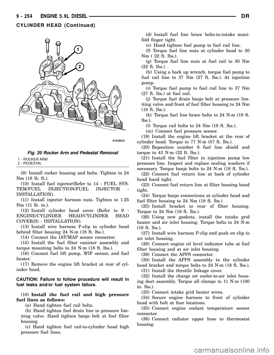
Fig. 20 Rocker Arm and Pedestal Removal
1 - ROCKER ARM
2 - PEDESTAL
9 - 254 ENGINE 5.9L DIESELDR
CYLINDER HEAD (Continued)
Page 1479 of 2627
INTAKE/EXHAUST VALVES &
SEATS
DESCRIPTION
The valves are made of heat resistant steel, and
have chrome plated stems to prevent scuffing. The
intake and exhaust valves are both similar in head
diameter and overall length, but they have unique
face angles which makes them non-interchangeable.
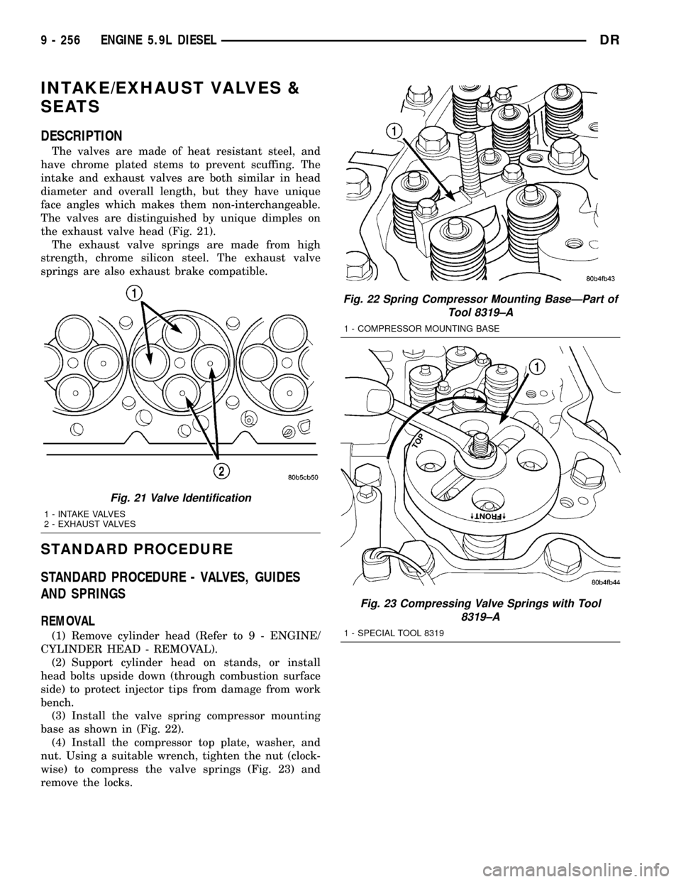
The valves are distinguished by unique dimples on
the exhaust valve head (Fig. 21).
The exhaust valve springs are made from high
strength, chrome silicon steel. The exhaust valve
springs are also exhaust brake compatible.
STANDARD PROCEDURE
STANDARD PROCEDURE - VALVES, GUIDES
AND SPRINGS
REMOVAL
(1) Remove cylinder head (Refer to 9 - ENGINE/
CYLINDER HEAD - REMOVAL).
(2) Support cylinder head on stands, or install
head bolts upside down (through combustion surface
side) to protect injector tips from damage from work
bench.
(3) Install the valve spring compressor mounting
base as shown in (Fig. 22).
(4) Install the compressor top plate, washer, and
nut. Using a suitable wrench, tighten the nut (clock-
wise) to compress the valve springs (Fig. 23) and
remove the locks.
Fig. 22 Spring Compressor Mounting BaseÐPart of
Tool 8319±A
1 - COMPRESSOR MOUNTING BASE
Fig. 23 Compressing Valve Springs with Tool
8319±A
1 - SPECIAL TOOL 8319
Fig. 21 Valve Identification
1 - INTAKE VALVES
2 - EXHAUST VALVES
9 - 256 ENGINE 5.9L DIESELDR
Page 1482 of 2627
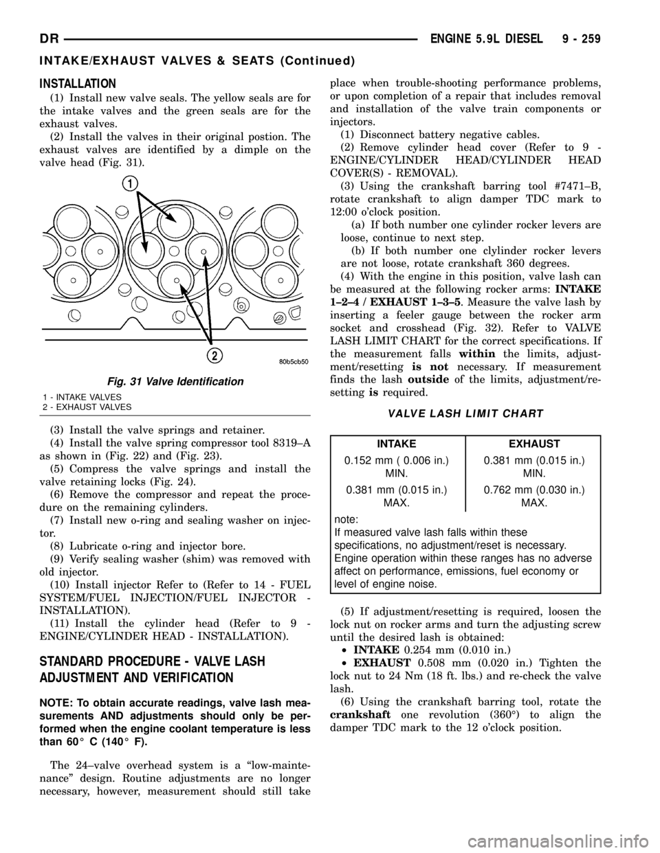
INSTALLATION
(1) Install new valve seals. The yellow seals are for
the intake valves and the green seals are for the
exhaust valves.
(2) Install the valves in their original postion. The
exhaust valves are identified by a dimple on the
valve head (Fig. 31).
(3) Install the valve springs and retainer.
(4) Install the valve spring compressor tool 8319±A
as shown in (Fig. 22) and (Fig. 23).
(5) Compress the valve springs and install the
valve retaining locks (Fig. 24).
(6) Remove the compressor and repeat the proce-
dure on the remaining cylinders.
(7) Install new o-ring and sealing washer on injec-
tor.
(8) Lubricate o-ring and injector bore.
(9) Verify sealing washer (shim) was removed with
old injector.
(10) Install injector Refer to (Refer to 14 - FUEL
SYSTEM/FUEL INJECTION/FUEL INJECTOR -
INSTALLATION).
(11) Install the cylinder head (Refer to 9 -
ENGINE/CYLINDER HEAD - INSTALLATION).
STANDARD PROCEDURE - VALVE LASH
ADJUSTMENT AND VERIFICATION
NOTE: To obtain accurate readings, valve lash mea-
surements AND adjustments should only be per-
formed when the engine coolant temperature is less
than 60É C (140É F).
The 24±valve overhead system is a ªlow-mainte-
nanceº design. Routine adjustments are no longer
necessary, however, measurement should still takeplace when trouble-shooting performance problems,
or upon completion of a repair that includes removal
and installation of the valve train components or
injectors.
(1) Disconnect battery negative cables.
(2) Remove cylinder head cover (Refer to 9 -
ENGINE/CYLINDER HEAD/CYLINDER HEAD
COVER(S) - REMOVAL).
(3) Using the crankshaft barring tool #7471±B,
rotate crankshaft to align damper TDC mark to
12:00 o'clock position.
(a) If both number one cylinder rocker levers are
loose, continue to next step.
(b) If both number one clylinder rocker levers
are not loose, rotate crankshaft 360 degrees.
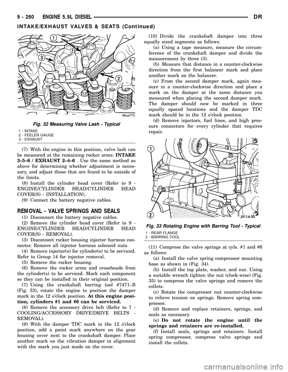
(4) With the engine in this position, valve lash can
be measured at the following rocker arms:INTAKE
1±2±4 / EXHAUST 1±3±5. Measure the valve lash by
inserting a feeler gauge between the rocker arm
socket and crosshead (Fig. 32). Refer to VALVE
LASH LIMIT CHART for the correct specifications. If
the measurement fallswithinthe limits, adjust-
ment/resettingis notnecessary. If measurement
finds the lashoutsideof the limits, adjustment/re-
settingisrequired.
VALVE LASH LIMIT CHART
INTAKE EXHAUST
0.152 mm ( 0.006 in.)
MIN.0.381 mm (0.015 in.)
MIN.
0.381 mm (0.015 in.)
MAX.0.762 mm (0.030 in.)
MAX.
note:
If measured valve lash falls within these
specifications, no adjustment/reset is necessary.
Engine operation within these ranges has no adverse
affect on performance, emissions, fuel economy or
level of engine noise.
(5) If adjustment/resetting is required, loosen the
lock nut on rocker arms and turn the adjusting screw
until the desired lash is obtained:
²INTAKE0.254 mm (0.010 in.)
²EXHAUST0.508 mm (0.020 in.) Tighten the
lock nut to 24 Nm (18 ft. lbs.) and re-check the valve
lash.
(6) Using the crankshaft barring tool, rotate the
crankshaftone revolution (360É) to align the
damper TDC mark to the 12 o'clock position.
Fig. 31 Valve Identification
1 - INTAKE VALVES
2 - EXHAUST VALVES
DRENGINE 5.9L DIESEL 9 - 259
INTAKE/EXHAUST VALVES & SEATS (Continued)
Page 1483 of 2627
(7) With the engine in this position, valve lash can
be measured at the remaining rocker arms:INTAKE
3±5±6 / EXHAUST 2±4±6. Use the same method as
above for determining whether adjustment is neces-
sary, and adjust those that are found to be outside of
the limits.
(8) Install the cylinder head cover (Refer to 9 -
ENGINE/CYLINDER HEAD/CYLINDER HEAD
COVER(S) - INSTALLATION).
(9) Connect the battery negative cables.
REMOVAL - VALVE SPRINGS AND SEALS
(1) Disconnect the battery negative cables.
(2) Remove the cylinder head cover (Refer to 9 -
ENGINE/CYLINDER HEAD/CYLINDER HEAD
COVER(S) - REMOVAL).
(3) Disconnect rocker housing injector harness con-
nector. Remove all injector harness solenoid nuts.
(4) Remove injector(s) for cylinder(s) to be serviced.
Refer to Group 14 for injector removal.
(5) Remove the rocker housing.
(6) Remove the rocker arms and crossheads from
the cylinder(s) to be serviced. Mark each component
so they can be installed in their original position.
(7) Using the crankshaft barring tool #7471±B
(Fig. 33), rotate the engine to position the damper
mark in the 12 o'clock position.At this engine posi-
tion, cylinders #1 and #6 can be serviced.
(8) Remove the accessory drive belt (Refer to 7 -
COOLING/ACCESSORY DRIVE/DRIVE BELTS -
REMOVAL).
(9) With the damper TDC mark in the 12 o'clock
position, add a paint mark anywhere on the gear
housing cover next to the crankshaft damper. Place
another mark on the vibration damper in alignment
with the mark you just made on the cover.(10) Divide the crankshaft damper into three
equally sized segments as follows:
(a) Using a tape measure, measure the circum-
ference of the crankshaft damper and divide the
measurement by three (3).
(b) Measure that distance in a counter-clockwise
direction from the first balancer mark and place
another mark on the balancer.
(c) From the second damper mark, again mea-
sure in a counter-clockwise direction and place a
mark on the damper at the same distance you
measured when placing the second damper mark.
The damper should now be marked in three
equally spaced locations and the damper TDC
mark should be in the 12 o'clock position.
(d) Remove injectors, fuel lines, and high pres-
sure connectors for every cylinder that requires
repair.
(11) Compress the valve springs at cyls. #1 and #6
as follows:
(a) Install the valve spring compressor mounting
base as shown in (Fig. 34).
(b) Install the top plate, washer, and nut. Using
a suitable wrench tighten the nut (clock-wise) (Fig.
35) to compress the valve springs and remove the
collets.
(c) Rotate the compressor nut counter-clockwise
to relieve tension on springs. Remove spring com-
pressor.
(d) Remove and replace retainers, springs, and
seals as necessary.
(e)Do not rotate the engine until the
springs and retainers are re-installed.
(f) Install seals, springs and retainers. Install
spring compressor, compress valve springs and
install the collets.
Fig. 32 Measuring Valve Lash - Typical
1 - INTAKE
2 - FEELER GAUGE
3 - EXHAUST
Fig. 33 Rotating Engine with Barring Tool - Typical
1 - REAR FLANGE
2 - BARRING TOOL
9 - 260 ENGINE 5.9L DIESELDR
INTAKE/EXHAUST VALVES & SEATS (Continued)
Page 1494 of 2627
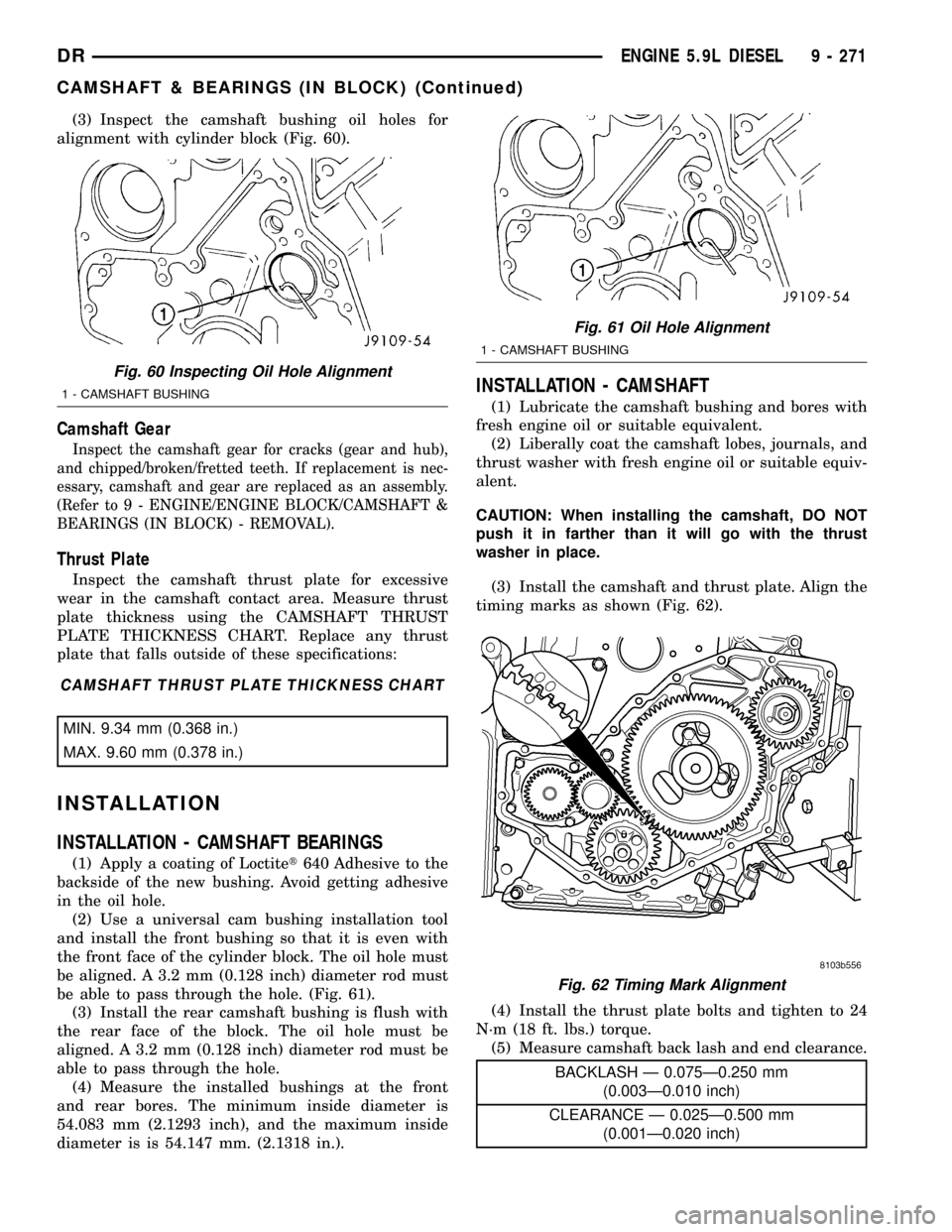
(3) Inspect the camshaft bushing oil holes for
alignment with cylinder block (Fig. 60).
Camshaft Gear
Inspect the camshaft gear for cracks (gear and hub),
and chipped/broken/fretted teeth. If replacement is nec-
essary, camshaft and gear are replaced as an assembly.
(Refer to 9 - ENGINE/ENGINE BLOCK/CAMSHAFT &
BEARINGS (IN BLOCK) - REMOVAL).
Thrust Plate
Inspect the camshaft thrust plate for excessive
wear in the camshaft contact area. Measure thrust
plate thickness using the CAMSHAFT THRUST
PLATE THICKNESS CHART. Replace any thrust
plate that falls outside of these specifications:
CAMSHAFT THRUST PLATE THICKNESS CHART
MIN. 9.34 mm (0.368 in.)
MAX. 9.60 mm (0.378 in.)
INSTALLATION
INSTALLATION - CAMSHAFT BEARINGS
(1) Apply a coating of Loctitet640 Adhesive to the
backside of the new bushing. Avoid getting adhesive
in the oil hole.
(2) Use a universal cam bushing installation tool
and install the front bushing so that it is even with
the front face of the cylinder block. The oil hole must
be aligned. A 3.2 mm (0.128 inch) diameter rod must
be able to pass through the hole. (Fig. 61).
(3) Install the rear camshaft bushing is flush with
the rear face of the block. The oil hole must be
aligned. A 3.2 mm (0.128 inch) diameter rod must be
able to pass through the hole.
(4) Measure the installed bushings at the front
and rear bores. The minimum inside diameter is
54.083 mm (2.1293 inch), and the maximum inside
diameter is is 54.147 mm. (2.1318 in.).
INSTALLATION - CAMSHAFT
(1) Lubricate the camshaft bushing and bores with
fresh engine oil or suitable equivalent.
(2) Liberally coat the camshaft lobes, journals, and
thrust washer with fresh engine oil or suitable equiv-
alent.
CAUTION: When installing the camshaft, DO NOT
push it in farther than it will go with the thrust
washer in place.
(3) Install the camshaft and thrust plate. Align the
timing marks as shown (Fig. 62).
(4) Install the thrust plate bolts and tighten to 24
N´m (18 ft. lbs.) torque.
(5) Measure camshaft back lash and end clearance.
BACKLASH Ð 0.075Ð0.250 mm
(0.003Ð0.010 inch)
CLEARANCE Ð 0.025Ð0.500 mm
(0.001Ð0.020 inch)
Fig. 60 Inspecting Oil Hole Alignment
1 - CAMSHAFT BUSHING
Fig. 61 Oil Hole Alignment
1 - CAMSHAFT BUSHING
Fig. 62 Timing Mark Alignment
DRENGINE 5.9L DIESEL 9 - 271
CAMSHAFT & BEARINGS (IN BLOCK) (Continued)
Page 1495 of 2627
(6) Remove the wooden dowel rods and rubber
bands from the tappets.
(7) Lubricate the push rods with engine oil and
install in their original location.Verify that they
are seated in the tappets.
(8) Lubricate the valve tips with engine oil and
install the crossheads in their original locations.
(9) Lubricate the crossheads and push rod sockets
with engine oil and install the rocker arms and ped-
estals in their original locations. Tighten bolts to 36
N´m (27 ft. lbs.) torque.
(10)Verify valve lash adjustment (Refer to 9 -
ENGINE/CYLINDER HEAD/INTAKE/EXHAUST
VALVES & SEATS - STANDARD PROCEDURE).
(11) Install the cylinder head cover and reusable
gasket (Refer to 9 - ENGINE/CYLINDER HEAD/
CYLINDER HEAD COVER(S) - INSTALLATION).
(12) Install gear housing cover (Refer to 9 -
ENGINE/VALVE TIMING/GEAR HOUSING COVER
- INSTALLATION). Install front crankshaft dust
seal.
(13) Install the crankshaft damper with the speed
indicator ring (Refer to 9 - ENGINE/ENGINE
BLOCK/VIBRATION DAMPER - INSTALLATION).
(14) Install the fan support/hub assembly Refer to
(Refer to 7 - COOLING/ENGINE/RADIATOR FAN -
INSTALLATION).
(15) Install the power steering pump.
(16) Install accessory drive belt tensioner. Torque
bolt to 43 Nm (32 ft. lbs.).
(17) Install the accessory drive belt (Refer to 7 -
COOLING/ACCESSORY DRIVE/DRIVE BELTS -
INSTALLATION).
(18) Install the charge air cooler (with a/c con-
denser and auxiliary transmission oil cooler, if
equipped) and tighten the mounting bolts to 2 N´m
(17 in. lbs.) torque.
(19) Connect charge air cooler inlet and outlet
pipes. Tighten clamps to 11 N´m (95 in. lbs.) torque.
(20) Install the radiator upper support panel.
(21) Close radiator petcock and lower the radiator
into the engine compartment. Tighten the mounting
bolts to 11 N´m (95 in. lbs.) torque.
(22) Raise vehicle on hoist.
(23) Connect radiator lower hose and install
clamp.
(24) Connect transmission auxiliary oil cooler lines
(if equipped).
(25) Lower vehicle.
(26) Install the fan shroud and tighten the mount-
ing screws to 6 N´m (50 in. lbs.) torque.
(27) Install the electronically controlled viscous
fan/drive assembly. Connect harness connector.(Refer
to 7 - COOLING/ENGINE/RADIATOR FAN -
INSTALLATION).(28) Install the coolant recovery and windshield
washer fluid reservoirs to the fan shroud.
(29) Connect the coolant recovery hose to the radi-
ator filler neck.
(30) Add engine coolant (Refer to 7 - COOLING -
STANDARD PROCEDURE).
(31) Charge A/C system with refrigerant (if A/C
equipped) (Refer to 24 - HEATING & AIR CONDI-
TIONING/PLUMBING - STANDARD PROCEDURE).
(32) Connect the battery negative cables.
(33) Start engine and check for engine oil and cool-
ant leaks.
CONNECTING ROD BEARINGS
STANDARD PROCEDURE - CONNECTING ROD
BEARING AND CRANKSHAFT JOURNAL
CLEARANCE
(1) Measure the connecting rod bore with bearings
removedand the bolts tightened to 100 N´m (73 ft.
lbs.) torque..
(2) Measure the connecting rod bore with the bear-
ingsinstalledand the bolts tightened to 100 N´m
(73 ft. lbs.) torque.
Measure within 20É arc from each side of the part-
ing line. Also measure 90É from parting line.
Record the smallest and largest diameter.
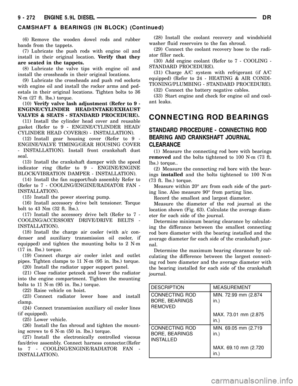
Measure the diameter of the rod journal at the
location shown (Fig. 63). Calculate the average diam-
eter for each side of the journal.
Determine minimum bearing clearance by calculat-
ing the differance between the smallest connecting
rod bore diameter with the bearing installed and the
average diameter for each side of the crankshaft jour-
nal.
Determine the maximum bearing clearance by cal-
culating the difference between the largest connect-
ing rod bore diameter and the average diameter with
the bearing installed for each side of the crankshaft
journal.
DESCRIPTION MEASUREMENT
CONNECTING ROD
BORE, BEARINGS
REMOVEDMIN. 72.99 mm (2.874
in.)
MAX. 73.01 mm (2.875
in.)
CONNECTING ROD
BORE, BEARINGS
INSTALLEDMIN. 69.05 mm (2.719
in.)
MAX. 69.10 mm (2.720
in.)
9 - 272 ENGINE 5.9L DIESELDR
CAMSHAFT & BEARINGS (IN BLOCK) (Continued)