1998 DODGE RAM 1500 Washer
[x] Cancel search: WasherPage 1646 of 2627
INSTALLATION
(1)Inspect fuel injector:
(a) Look for burrs on injector inlet.
(b) Check nozzle holes for hole erosion or plug-
ging.
(c) Inspect end of nozzle for burrs or rough
machine marks.
(d) Look for cracks at nozzle end.
(e) If any of these conditions occur, replace injec-
tor.
(2) Thoroughly clean fuel injector cylinder head
bore. Blow out bore hole with compressed air.
(3) The bottom of fuel injector is sealed to cylinder
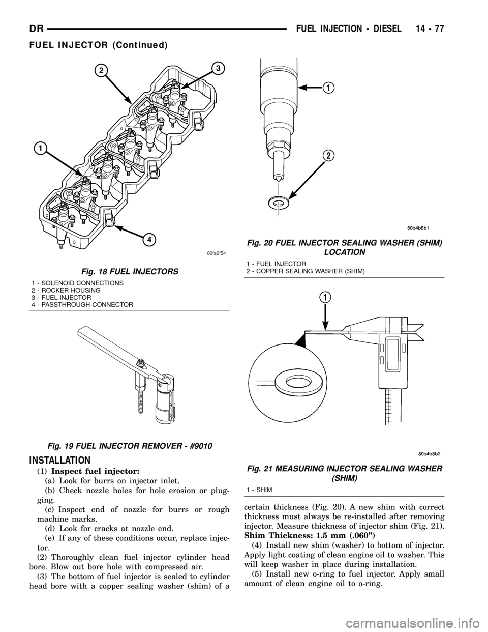
head bore with a copper sealing washer (shim) of acertain thickness (Fig. 20). A new shim with correct
thickness must always be re-installed after removing
injector. Measure thickness of injector shim (Fig. 21).
Shim Thickness: 1.5 mm (.060º)
(4) Install new shim (washer) to bottom of injector.
Apply light coating of clean engine oil to washer. This
will keep washer in place during installation.
(5) Install new o-ring to fuel injector. Apply small
amount of clean engine oil to o-ring.
Fig. 18 FUEL INJECTORS
1 - SOLENOID CONNECTIONS
2 - ROCKER HOUSING
3 - FUEL INJECTOR
4 - PASSTHROUGH CONNECTOR
Fig. 19 FUEL INJECTOR REMOVER - #9010
Fig. 20 FUEL INJECTOR SEALING WASHER (SHIM)
LOCATION
1 - FUEL INJECTOR
2 - COPPER SEALING WASHER (SHIM)
Fig. 21 MEASURING INJECTOR SEALING WASHER
(SHIM)
1 - SHIM
DRFUEL INJECTION - DIESEL 14 - 77
FUEL INJECTOR (Continued)
Page 1676 of 2627
(4) Disconnect and cap the fluid hoses from steer-
ing gear (Refer to 19 - STEERING/PUMP/HOSES -
REMOVAL).
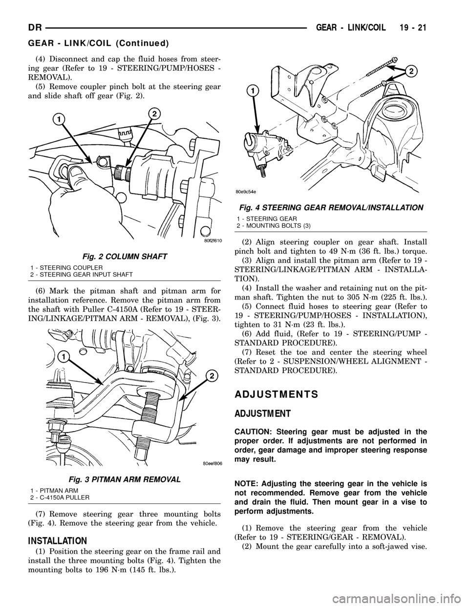
(5) Remove coupler pinch bolt at the steering gear
and slide shaft off gear (Fig. 2).
(6) Mark the pitman shaft and pitman arm for
installation reference. Remove the pitman arm from
the shaft with Puller C-4150A (Refer to 19 - STEER-
ING/LINKAGE/PITMAN ARM - REMOVAL), (Fig. 3).
(7) Remove steering gear three mounting bolts
(Fig. 4). Remove the steering gear from the vehicle.
INSTALLATION
(1) Position the steering gear on the frame rail and
install the three mounting bolts (Fig. 4). Tighten the
mounting bolts to 196 N´m (145 ft. lbs.).(2) Align steering coupler on gear shaft. Install
pinch bolt and tighten to 49 N´m (36 ft. lbs.) torque.
(3) Align and install the pitman arm (Refer to 19 -
STEERING/LINKAGE/PITMAN ARM - INSTALLA-
TION).
(4) Install the washer and retaining nut on the pit-
man shaft. Tighten the nut to 305 N´m (225 ft. lbs.).
(5) Connect fluid hoses to steering gear (Refer to
19 - STEERING/PUMP/HOSES - INSTALLATION),
tighten to 31 N´m (23 ft. lbs.).
(6) Add fluid, (Refer to 19 - STEERING/PUMP -
STANDARD PROCEDURE).
(7) Reset the toe and center the steering wheel
(Refer to 2 - SUSPENSION/WHEEL ALIGNMENT -
STANDARD PROCEDURE).
ADJUSTMENTS
ADJUSTMENT
CAUTION: Steering gear must be adjusted in the
proper order. If adjustments are not performed in
order, gear damage and improper steering response
may result.
NOTE: Adjusting the steering gear in the vehicle is
not recommended. Remove gear from the vehicle
and drain the fluid. Then mount gear in a vise to
perform adjustments.
(1) Remove the steering gear from the vehicle
(Refer to 19 - STEERING/GEAR - REMOVAL).
(2) Mount the gear carefully into a soft-jawed vise.
Fig. 2 COLUMN SHAFT
1 - STEERING COUPLER
2 - STEERING GEAR INPUT SHAFT
Fig. 3 PITMAN ARM REMOVAL
1 - PITMAN ARM
2 - C-4150A PULLER
Fig. 4 STEERING GEAR REMOVAL/INSTALLATION
1 - STEERING GEAR
2 - MOUNTING BOLTS (3)
DRGEAR - LINK/COIL 19 - 21
GEAR - LINK/COIL (Continued)
Page 1680 of 2627
PITMAN SHAFT SEAL
REMOVAL
REMOVAL - GAS ENGINE
(1) Seperate the pitman arm from the gear box
(Refer to 19 - STEERING/LINKAGE/PITMAN ARM -
REMOVAL).
(2) Clean exposed end of pitman shaft and housing
with a wire brush.
(3) Rotate the steering wheel from stop to stop and
count the number of turns.
(4) Center the steering wheel by rotating it from
the stop back 1 1/2 turns to achieve center position.
(5) Remove the pitman shaft cover bolts.
NOTE: The pitman shaft will not clear the housing if
it is not centered.
(6) Remove the pitman shaft from the gear.
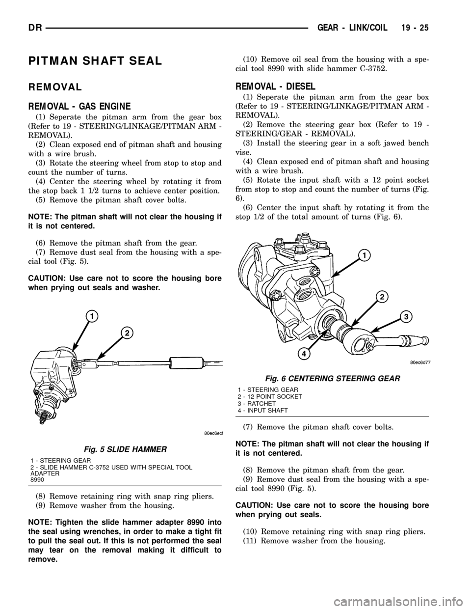
(7) Remove dust seal from the housing with a spe-
cial tool (Fig. 5).
CAUTION: Use care not to score the housing bore
when prying out seals and washer.
(8) Remove retaining ring with snap ring pliers.
(9) Remove washer from the housing.
NOTE: Tighten the slide hammer adapter 8990 into
the seal using wrenches, in order to make a tight fit
to pull the seal out. If this is not performed the seal
may tear on the removal making it difficult to
remove.(10) Remove oil seal from the housing with a spe-
cial tool 8990 with slide hammer C-3752.
REMOVAL - DIESEL
(1) Seperate the pitman arm from the gear box
(Refer to 19 - STEERING/LINKAGE/PITMAN ARM -
REMOVAL).
(2) Remove the steering gear box (Refer to 19 -
STEERING/GEAR - REMOVAL).
(3) Install the steering gear in a soft jawed bench
vise.
(4) Clean exposed end of pitman shaft and housing
with a wire brush.
(5) Rotate the input shaft with a 12 point socket
from stop to stop and count the number of turns (Fig.
6).
(6) Center the input shaft by rotating it from the
stop 1/2 of the total amount of turns (Fig. 6).
(7) Remove the pitman shaft cover bolts.
NOTE: The pitman shaft will not clear the housing if
it is not centered.
(8) Remove the pitman shaft from the gear.
(9) Remove dust seal from the housing with a spe-
cial tool 8990 (Fig. 5).
CAUTION: Use care not to score the housing bore
when prying out seals.
(10) Remove retaining ring with snap ring pliers.
(11) Remove washer from the housing.
Fig. 5 SLIDE HAMMER
1 - STEERING GEAR
2 - SLIDE HAMMER C-3752 USED WITH SPECIAL TOOL
ADAPTER
8990
Fig. 6 CENTERING STEERING GEAR
1 - STEERING GEAR
2 - 12 POINT SOCKET
3 - RATCHET
4 - INPUT SHAFT
DRGEAR - LINK/COIL 19 - 25
Page 1681 of 2627
NOTE: Tighten the slide hammer adapter 8990 into
the seal using wrenches, in order to make a tight fit
to pull the seal out. If this is not performed the seal
may tear on the removal making it difficult to
remove.
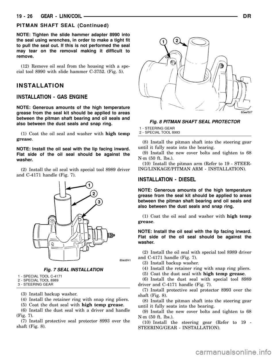
(12) Remove oil seal from the housing with a spe-
cial tool 8990 with slide hammer C-3752. (Fig. 5).
INSTALLATION
INSTALLATION - GAS ENGINE
NOTE: Generous amounts of the high temperature
grease from the seal kit should be applied to areas
between the pitman shaft bearing and oil seals and
also between the dust seals and snap ring.
(1) Coat the oil seal and washer withhigh temp
grease.
NOTE: Install the oil seal with the lip facing inward.
Flat side of the oil seal should be against the
washer.
(2) Install the oil seal with special tool 8989 driver
and C-4171 handle (Fig. 7).
(3) Install backup washer.
(4) Install the retainer ring with snap ring pliers.
(5) Coat the dust seal withhigh temp grease.
(6) Install the dust seal with a driver and handle
(Fig. 7).
(7) Install protective seal protector 8993 over the
shaft (Fig. 8).(8) Install the pitman shaft into the steering gear
until it fully seats into the bearing.
(9) Install the new cover bolts and tighten to 68
N´m (50 ft. lbs.).
(10) Install the pitman arm (Refer to 19 - STEER-
ING/LINKAGE/PITMAN ARM - INSTALLATION).
INSTALLATION - DIESEL
NOTE: Generous amounts of the high temperature
grease from the seal kit should be applied to areas
between the pitman shaft bearing and oil seals and
also between the dust seals and snap ring.
(1) Coat the oil seal and washer withhigh temp
grease.
NOTE: Install the oil seal with the lip facing inward.
Flat side of the oil seal should be against the
washer.
(2) Install the oil seal with special tool 8989 driver
and C-4171 handle (Fig. 7).
(3) Install backup washer.
(4) Install the retainer ring with snap ring pliers.
(5) Coat the dust seal withhigh temp grease.
(6) Install the dust seal with special tool 8989
driver and C-4171 handle (Fig. 7).
(7) Install protective seal protector 8993 over the
shaft (Fig. 8).
(8) Install the pitman shaft into the steering gear
until it fully seats into the bearing.
(9) Install the new cover bolts and tighten to 68
N´m (50 ft. lbs.).
(10) Install the steering gear (Refer to 19 -
STEERING/GEAR - INSTALLATION).
Fig. 7 SEAL INSTALLATION
1 - SPECIAL TOOL C-4171
2 - SPECIAL TOOL 8989
3 - STEERING GEAR
Fig. 8 PITMAN SHAFT SEAL PROTECTOR
1 - STEERING GEAR
2 - SPECIAL TOOL 8993
19 - 26 GEAR - LINK/COILDR
PITMAN SHAFT SEAL (Continued)
Page 1692 of 2627
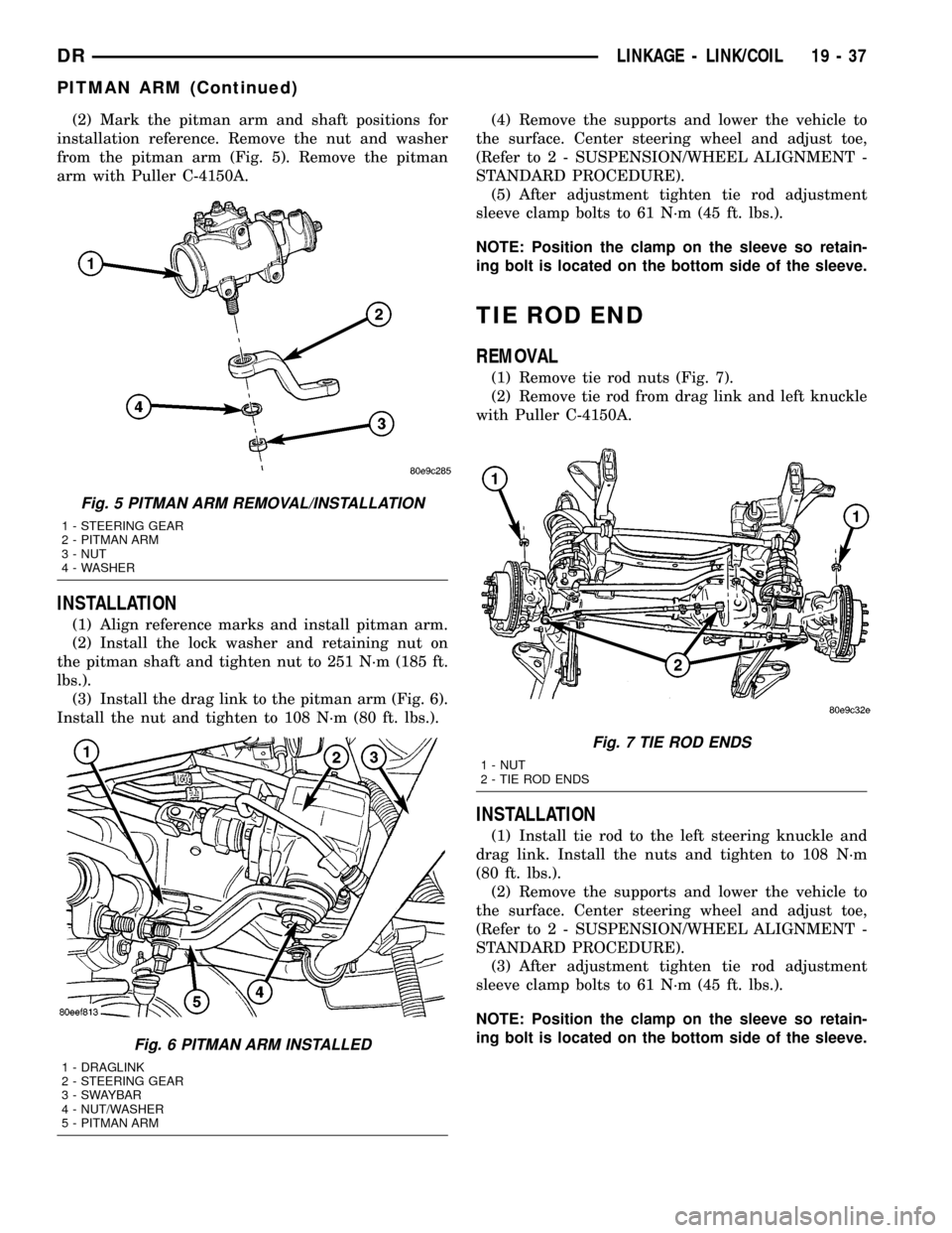
(2) Mark the pitman arm and shaft positions for
installation reference. Remove the nut and washer
from the pitman arm (Fig. 5). Remove the pitman
arm with Puller C-4150A.
INSTALLATION
(1) Align reference marks and install pitman arm.
(2) Install the lock washer and retaining nut on
the pitman shaft and tighten nut to 251 N´m (185 ft.
lbs.).
(3) Install the drag link to the pitman arm (Fig. 6).
Install the nut and tighten to 108 N´m (80 ft. lbs.).(4) Remove the supports and lower the vehicle to
the surface. Center steering wheel and adjust toe,
(Refer to 2 - SUSPENSION/WHEEL ALIGNMENT -
STANDARD PROCEDURE).
(5) After adjustment tighten tie rod adjustment
sleeve clamp bolts to 61 N´m (45 ft. lbs.).
NOTE: Position the clamp on the sleeve so retain-
ing bolt is located on the bottom side of the sleeve.
TIE ROD END
REMOVAL
(1) Remove tie rod nuts (Fig. 7).
(2) Remove tie rod from drag link and left knuckle
with Puller C-4150A.
INSTALLATION
(1) Install tie rod to the left steering knuckle and
drag link. Install the nuts and tighten to 108 N´m
(80 ft. lbs.).
(2) Remove the supports and lower the vehicle to
the surface. Center steering wheel and adjust toe,
(Refer to 2 - SUSPENSION/WHEEL ALIGNMENT -
STANDARD PROCEDURE).
(3) After adjustment tighten tie rod adjustment
sleeve clamp bolts to 61 N´m (45 ft. lbs.).
NOTE: Position the clamp on the sleeve so retain-
ing bolt is located on the bottom side of the sleeve.
Fig. 5 PITMAN ARM REMOVAL/INSTALLATION
1 - STEERING GEAR
2 - PITMAN ARM
3 - NUT
4 - WASHER
Fig. 6 PITMAN ARM INSTALLED
1 - DRAGLINK
2 - STEERING GEAR
3 - SWAYBAR
4 - NUT/WASHER
5 - PITMAN ARM
Fig. 7 TIE ROD ENDS
1 - NUT
2 - TIE ROD ENDS
DRLINKAGE - LINK/COIL 19 - 37
PITMAN ARM (Continued)
Page 1715 of 2627
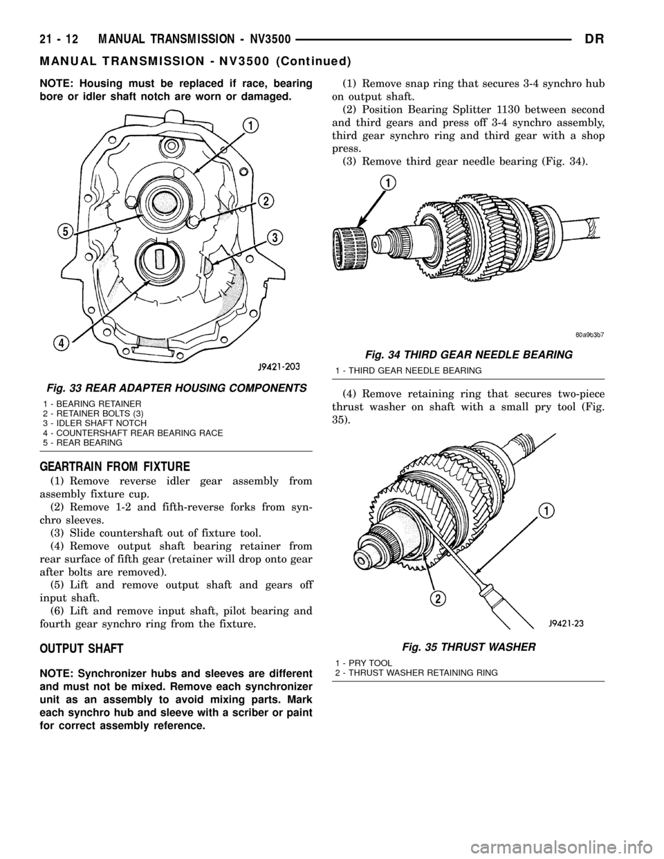
NOTE: Housing must be replaced if race, bearing
bore or idler shaft notch are worn or damaged.
GEARTRAIN FROM FIXTURE
(1) Remove reverse idler gear assembly from
assembly fixture cup.
(2) Remove 1-2 and fifth-reverse forks from syn-
chro sleeves.
(3) Slide countershaft out of fixture tool.
(4) Remove output shaft bearing retainer from
rear surface of fifth gear (retainer will drop onto gear
after bolts are removed).
(5) Lift and remove output shaft and gears off
input shaft.
(6) Lift and remove input shaft, pilot bearing and
fourth gear synchro ring from the fixture.
OUTPUT SHAFT
NOTE: Synchronizer hubs and sleeves are different
and must not be mixed. Remove each synchronizer
unit as an assembly to avoid mixing parts. Mark
each synchro hub and sleeve with a scriber or paint
for correct assembly reference.(1) Remove snap ring that secures 3-4 synchro hub
on output shaft.
(2) Position Bearing Splitter 1130 between second
and third gears and press off 3-4 synchro assembly,
third gear synchro ring and third gear with a shop
press.
(3) Remove third gear needle bearing (Fig. 34).
(4) Remove retaining ring that secures two-piece
thrust washer on shaft with a small pry tool (Fig.
35).
Fig. 33 REAR ADAPTER HOUSING COMPONENTS
1 - BEARING RETAINER
2 - RETAINER BOLTS (3)
3 - IDLER SHAFT NOTCH
4 - COUNTERSHAFT REAR BEARING RACE
5 - REAR BEARING
Fig. 34 THIRD GEAR NEEDLE BEARING
1 - THIRD GEAR NEEDLE BEARING
Fig. 35 THRUST WASHER
1-PRYTOOL
2 - THRUST WASHER RETAINING RING
21 - 12 MANUAL TRANSMISSION - NV3500DR
MANUAL TRANSMISSION - NV3500 (Continued)
Page 1716 of 2627
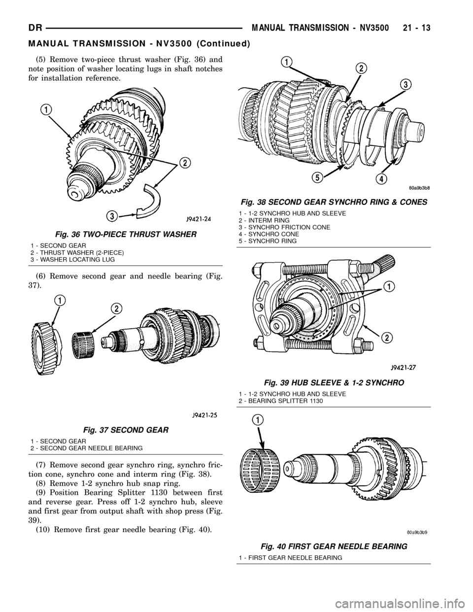
(5) Remove two-piece thrust washer (Fig. 36) and
note position of washer locating lugs in shaft notches
for installation reference.
(6) Remove second gear and needle bearing (Fig.
37).
(7) Remove second gear synchro ring, synchro fric-
tion cone, synchro cone and interm ring (Fig. 38).
(8) Remove 1-2 synchro hub snap ring.
(9) Position Bearing Splitter 1130 between first
and reverse gear. Press off 1-2 synchro hub, sleeve
and first gear from output shaft with shop press (Fig.
39).
(10) Remove first gear needle bearing (Fig. 40).
Fig. 36 TWO-PIECE THRUST WASHER
1 - SECOND GEAR
2 - THRUST WASHER (2-PIECE)
3 - WASHER LOCATING LUG
Fig. 37 SECOND GEAR
1 - SECOND GEAR
2 - SECOND GEAR NEEDLE BEARING
Fig. 38 SECOND GEAR SYNCHRO RING & CONES
1 - 1-2 SYNCHRO HUB AND SLEEVE
2 - INTERM RING
3 - SYNCHRO FRICTION CONE
4 - SYNCHRO CONE
5 - SYNCHRO RING
Fig. 39 HUB SLEEVE & 1-2 SYNCHRO
1 - 1-2 SYNCHRO HUB AND SLEEVE
2 - BEARING SPLITTER 1130
Fig. 40 FIRST GEAR NEEDLE BEARING
1 - FIRST GEAR NEEDLE BEARING
DRMANUAL TRANSMISSION - NV3500 21 - 13
MANUAL TRANSMISSION - NV3500 (Continued)
Page 1718 of 2627
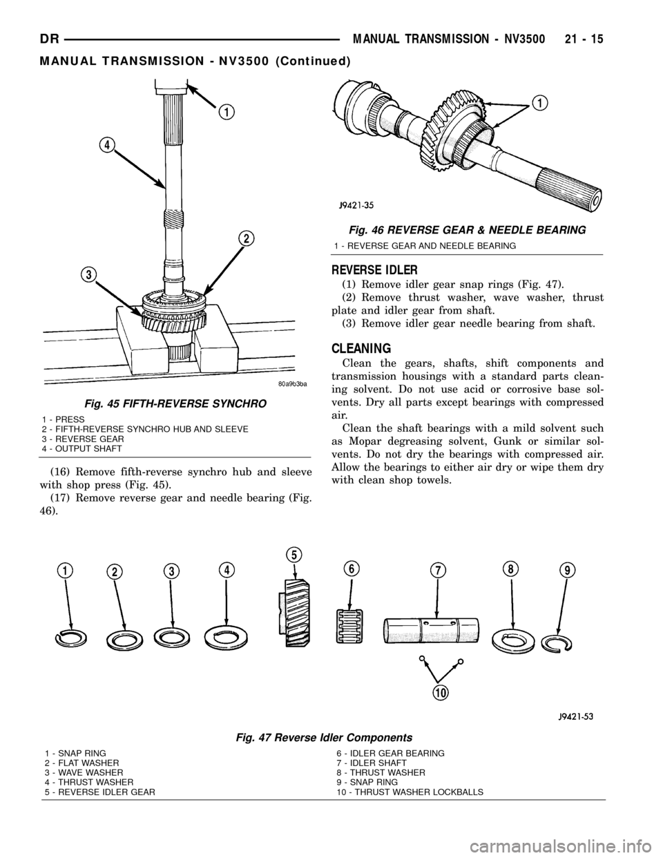
(16) Remove fifth-reverse synchro hub and sleeve
with shop press (Fig. 45).
(17) Remove reverse gear and needle bearing (Fig.
46).
REVERSE IDLER
(1) Remove idler gear snap rings (Fig. 47).
(2) Remove thrust washer, wave washer, thrust
plate and idler gear from shaft.
(3) Remove idler gear needle bearing from shaft.
CLEANING
Clean the gears, shafts, shift components and
transmission housings with a standard parts clean-
ing solvent. Do not use acid or corrosive base sol-
vents. Dry all parts except bearings with compressed
air.
Clean the shaft bearings with a mild solvent such
as Mopar degreasing solvent, Gunk or similar sol-
vents. Do not dry the bearings with compressed air.
Allow the bearings to either air dry or wipe them dry
with clean shop towels.
Fig. 45 FIFTH-REVERSE SYNCHRO
1 - PRESS
2 - FIFTH-REVERSE SYNCHRO HUB AND SLEEVE
3 - REVERSE GEAR
4 - OUTPUT SHAFT
Fig. 46 REVERSE GEAR & NEEDLE BEARING
1 - REVERSE GEAR AND NEEDLE BEARING
Fig. 47 Reverse Idler Components
1 - SNAP RING
2 - FLAT WASHER
3 - WAVE WASHER
4 - THRUST WASHER
5 - REVERSE IDLER GEAR6 - IDLER GEAR BEARING
7 - IDLER SHAFT
8 - THRUST WASHER
9 - SNAP RING
10 - THRUST WASHER LOCKBALLS
DRMANUAL TRANSMISSION - NV3500 21 - 15
MANUAL TRANSMISSION - NV3500 (Continued)