Page 1773 of 2627
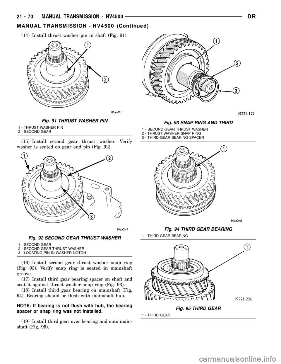
(14) Install thrust washer pin in shaft (Fig. 91).
(15) Install second gear thrust washer. Verify
washer is seated on gear and pin (Fig. 92).
(16) Install second gear thrust washer snap ring
(Fig. 93). Verify snap ring is seated in mainshaft
groove.
(17) Install third gear bearing spacer on shaft and
seat it against thrust washer snap ring (Fig. 93).
(18) Install third gear bearing on mainshaft (Fig.
94). Bearing should be flush with mainshaft hub.
NOTE: If bearing is not flush with hub, the bearing
spacer or snap ring was not installed.
(19) Install third gear over bearing and onto main-
shaft (Fig. 95).
Fig. 91 THRUST WASHER PIN
1 - THRUST WASHER PIN
2 - SECOND GEAR
Fig. 92 SECOND GEAR THRUST WASHER
1 - SECOND GEAR
2 - SECOND GEAR THRUST WASHER
3 - LOCATING PIN IN WASHER NOTCH
Fig. 93 SNAP RING AND THIRD
1 - SECOND GEAR THRUST WASHER
2 - THRUST WASHER SNAP RING
3 - THIRD GEAR BEARING SPACER
Fig. 94 THIRD GEAR BEARING
1 - THIRD GEAR BEARING
Fig. 95 THIRD GEAR
1 - THIRD GEAR
21 - 70 MANUAL TRANSMISSION - NV4500DR
MANUAL TRANSMISSION - NV4500 (Continued)
Page 1776 of 2627
(d) Compress first spring with flat blade screw-
driver and slide strut into position in hub slot.
Then work spring into seat in strut with small
hooked tool or screwdriver.
(e) Install second and third struts in same man-
ner as described in step (d).
(f) Work sleeve upward on hub until struts are
centered and seated in sleeve. Sleeve should be in
neutral position after seating struts.
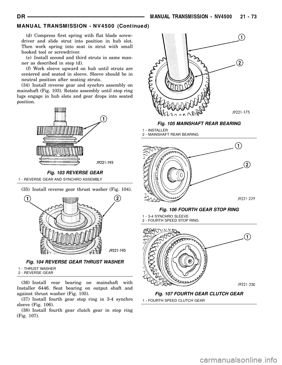
(34) Install reverse gear and synchro assembly on
mainshaft (Fig. 103). Rotate assembly until stop ring
lugs engage in hub slots and gear drops into seated
position.
(35) Install reverse gear thrust washer (Fig. 104).
(36) Install rear bearing on mainshaft with
Installer 6446. Seat bearing on output shaft and
against thrust washer (Fig. 105).
(37) Install fourth gear stop ring in 3-4 synchro
sleeve (Fig. 106).
(38) Install fourth gear clutch gear in stop ring
(Fig. 107).
Fig. 103 REVERSE GEAR
1 - REVERSE GEAR AND SYNCHRO ASSEMBLY
Fig. 104 REVERSE GEAR THRUST WASHER
1 - THRUST WASHER
2 - REVERSE GEAR
Fig. 105 MAINSHAFT REAR BEARING
1 - INSTALLER
2 - MAINSHAFT REAR BEARING
Fig. 106 FOURTH GEAR STOP RING
1 - 3-4 SYNCHRO SLEEVE
2 - FOURTH SPEED STOP RING
Fig. 107 FOURTH GEAR CLUTCH GEAR
1 - FOURTH SPEED CLUTCH GEAR
DRMANUAL TRANSMISSION - NV4500 21 - 73
MANUAL TRANSMISSION - NV4500 (Continued)
Page 1779 of 2627
(12) Install mainshaft fifth gear with Installer
6446 (Fig. 116). Gear is seated when it contacts rear
bearing.
COUNTERSHAFT FIFTH GEAR SYNCHRO
(1) Install thrust washer pin in countershaft (Fig.
117).
(2) Install thrust washer on countershaft. Turn
washer until pin engages in washer notch (Fig. 118).
NOTE: The flat side of washer faces the rear and
cone side faces the front.
(3) Lubricate and install fifth gear bearing on
countershaft (Fig. 119).
Fig. 115 REAR BEARING PLATE
1 - BEARING PLATE OIL HOLE (AT TOP)
2 - MAINSHAFT REAR BEARING PLATE
Fig. 116 MAINSHAFT FIFTH GEAR
1 - MAINSHAFT FIFTH GEAR
2 - INSTALLER
Fig. 117 FIFTH GEAR THRUST WASHER PIN
1 - THRUST WASHER PIN
2 - COUNTERSHAFT
Fig. 118 FIFTH GEAR THRUST WASHER
1 - PIN
2 - THRUST WASHER
Fig. 119 COUNTERSHAFT FIFTH GEAR BEARING
1 - COUNTERSHAFT
2 - FIFTH GEAR NEEDLE BEARING
21 - 76 MANUAL TRANSMISSION - NV4500DR
MANUAL TRANSMISSION - NV4500 (Continued)
Page 1781 of 2627
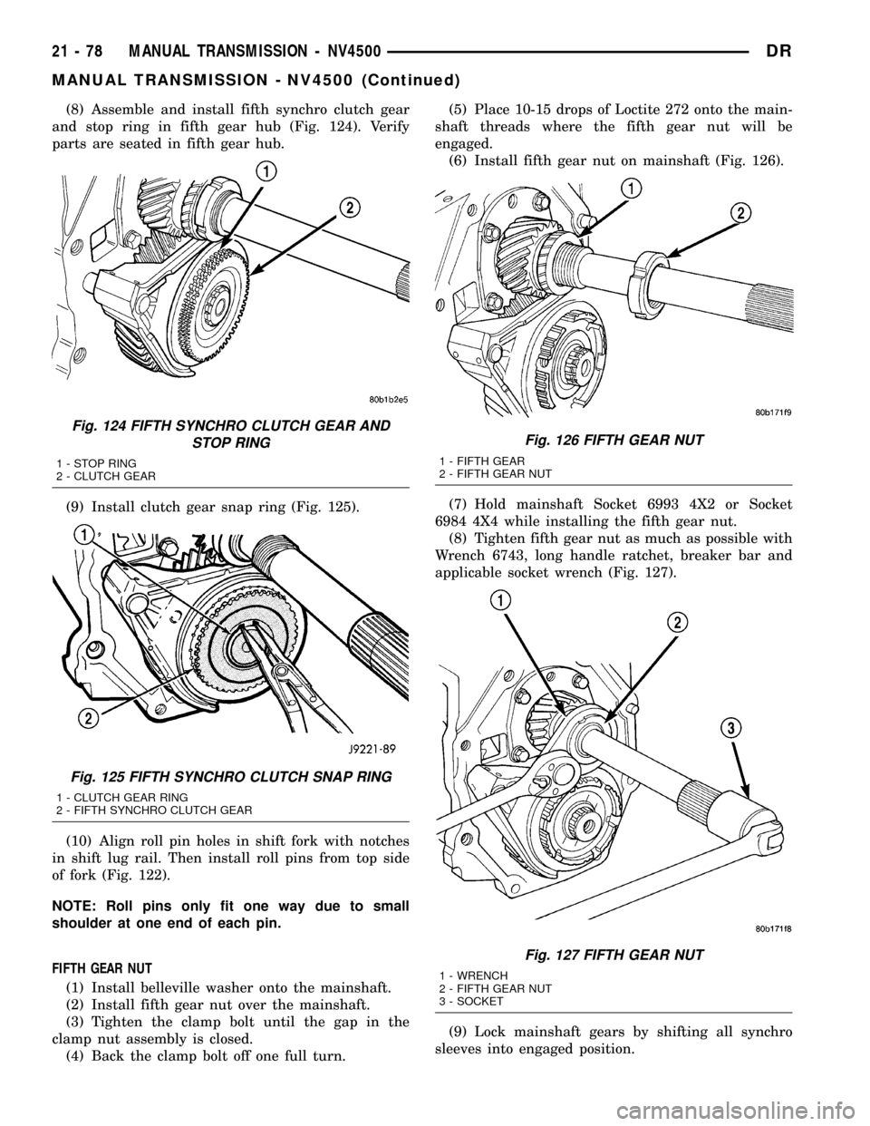
(8) Assemble and install fifth synchro clutch gear
and stop ring in fifth gear hub (Fig. 124). Verify
parts are seated in fifth gear hub.
(9) Install clutch gear snap ring (Fig. 125).
(10) Align roll pin holes in shift fork with notches
in shift lug rail. Then install roll pins from top side
of fork (Fig. 122).
NOTE: Roll pins only fit one way due to small
shoulder at one end of each pin.
FIFTH GEAR NUT
(1) Install belleville washer onto the mainshaft.
(2) Install fifth gear nut over the mainshaft.
(3) Tighten the clamp bolt until the gap in the
clamp nut assembly is closed.
(4) Back the clamp bolt off one full turn.(5) Place 10-15 drops of Loctite 272 onto the main-
shaft threads where the fifth gear nut will be
engaged.
(6) Install fifth gear nut on mainshaft (Fig. 126).
(7) Hold mainshaft Socket 6993 4X2 or Socket
6984 4X4 while installing the fifth gear nut.
(8) Tighten fifth gear nut as much as possible with
Wrench 6743, long handle ratchet, breaker bar and
applicable socket wrench (Fig. 127).
(9) Lock mainshaft gears by shifting all synchro
sleeves into engaged position.
Fig. 124 FIFTH SYNCHRO CLUTCH GEAR AND
STOP RING
1 - STOP RING
2 - CLUTCH GEAR
Fig. 125 FIFTH SYNCHRO CLUTCH SNAP RING
1 - CLUTCH GEAR RING
2 - FIFTH SYNCHRO CLUTCH GEAR
Fig. 126 FIFTH GEAR NUT
1 - FIFTH GEAR
2 - FIFTH GEAR NUT
Fig. 127 FIFTH GEAR NUT
1 - WRENCH
2 - FIFTH GEAR NUT
3 - SOCKET
21 - 78 MANUAL TRANSMISSION - NV4500DR
MANUAL TRANSMISSION - NV4500 (Continued)
Page 1797 of 2627
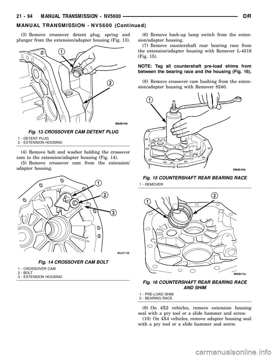
(3) Remove crossover detent plug, spring and
plunger from the extension/adapter housing (Fig. 13).
(4) Remove bolt and washer holding the crossover
cam to the extension/adapter housing (Fig. 14).
(5) Remove crossover cam from the extension/
adapter housing.(6) Remove back-up lamp switch from the exten-
sion/adapter housing.
(7) Remove countershaft rear bearing race from
the extension/adapter housing with Remover L-4518
(Fig. 15).
NOTE: Tag all countershaft pre-load shims from
between the bearing race and the housing (Fig. 16).
(8) Remove crossover cam bushing from the exten-
sion/adapter housing with Remover 8240.
(9) On 4X2 vehicles, remove extension housing
seal with a pry tool or a slide hammer and screw.
(10) On 4X4 vehicles, remove adapter housing seal
with a pry tool or a slide hammer and screw.
Fig. 13 CROSSOVER CAM DETENT PLUG
1 - DETENT PLUG
2 - EXTENSION HOUSING
Fig. 14 CROSSOVER CAM BOLT
1 - CROSSOVER CAM
2 - BOLT
3 - EXTENSION HOUSING
Fig. 15 COUNTERSHAFT REAR BEARING RACE
1 - REMOVER
Fig. 16 COUNTERSHAFT REAR BEARING RACE
AND SHIM
1 - PRE-LOAD SHIM
2 - BEARING RACE
21 - 94 MANUAL TRANSMISSION - NV5600DR
MANUAL TRANSMISSION - NV5600 (Continued)
Page 1798 of 2627
REVERSE GEAR
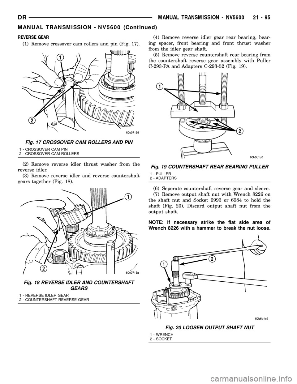
(1) Remove crossover cam rollers and pin (Fig. 17).
(2) Remove reverse idler thrust washer from the
reverse idler.
(3) Remove reverse idler and reverse countershaft
gears together (Fig. 18).(4) Remove reverse idler gear rear bearing, bear-
ing spacer, front bearing and front thrust washer
from the idler gear shaft.
(5) Remove reverse countershaft rear bearing from
the countershaft reverse gear assembly with Puller
C-293-PA and Adapters C-293-52 (Fig. 19).
(6) Seperate countershaft reverse gear and sleeve.
(7) Remove output shaft nut with Wrench 8226 on
the shaft nut and Socket 6993 or 6984 to hold the
shaft (Fig. 20). Discard output shaft nut from the
output shaft.
NOTE: If necessary strike the flat side area of
Wrench 8226 with a hammer to break the nut loose.
Fig. 17 CROSSOVER CAM ROLLERS AND PIN
1 - CROSSOVER CAM PIN
2 - CROSSOVER CAM ROLLERS
Fig. 18 REVERSE IDLER AND COUNTERSHAFT
GEARS
1 - REVERSE IDLER GEAR
2 - COUNTERSHAFT REVERSE GEAR
Fig. 19 COUNTERSHAFT REAR BEARING PULLER
1 - PULLER
2 - ADAPTERS
Fig. 20 LOOSEN OUTPUT SHAFT NUT
1 - WRENCH
2 - SOCKET
DRMANUAL TRANSMISSION - NV5600 21 - 95
MANUAL TRANSMISSION - NV5600 (Continued)
Page 1799 of 2627
(8) Remove output shaft ball bearing assembly and
reverse thrust washer from the output shaft (Fig.
21).
(9) Remove reverse gear, reverse gear synchronizer
cone, reverse gear outer blocker ring and reverse
gear bearing (Fig. 22).(10) Remove reverse gear bearing sleeve from the
output shaft (Fig. 23).
NOTE: If necessary heat the sleeve slightly with a
heat gun. Do not use a torch to heat the sleeve or
damage to the output shaft may occur.
(11) Remove roll-pin securing the reverse shift fork
to the reverse shift rail witha6mm(7/32 in.) punch
and hammer.
Fig. 21 OUTPUT SHAFT BEARING AND THRUST
WASHER
1 - OUTPUT SHAFT BALL BEARING
2 - THRUST WASHER
Fig. 22 REVERSE GEAR COMPONENTS
1 - REVERSE GEAR
2 - REVERSE BEARING
3 - BLOCKER RING
4 - FRICTION CONE
Fig. 23 REVERSE BEARING SLEEVE
1 - REVERSE GEAR BEARING SLEEVE
21 - 96 MANUAL TRANSMISSION - NV5600DR
MANUAL TRANSMISSION - NV5600 (Continued)
Page 1803 of 2627
OUTPUT SHAFT BEARINGS
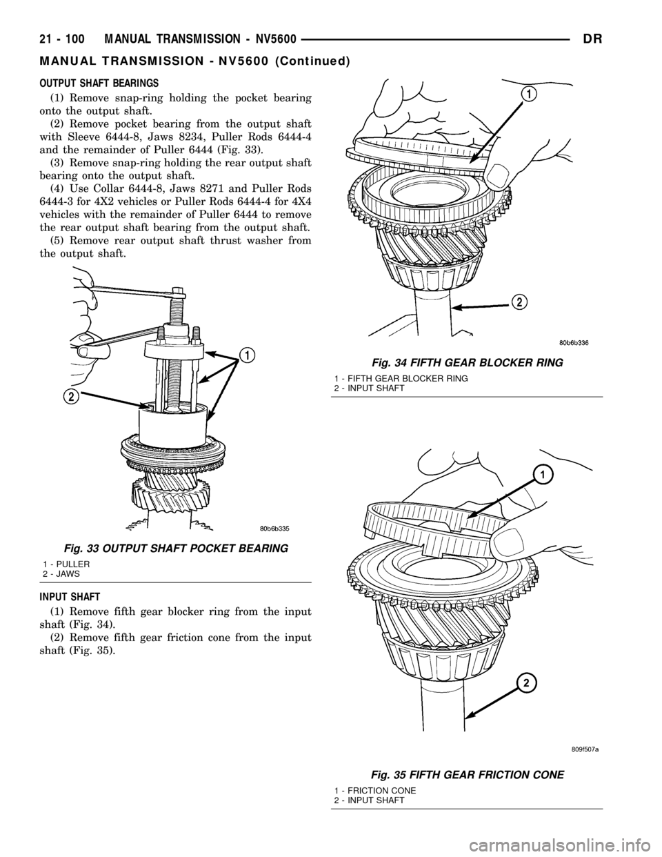
(1) Remove snap-ring holding the pocket bearing
onto the output shaft.
(2) Remove pocket bearing from the output shaft
with Sleeve 6444-8, Jaws 8234, Puller Rods 6444-4
and the remainder of Puller 6444 (Fig. 33).
(3) Remove snap-ring holding the rear output shaft
bearing onto the output shaft.
(4) Use Collar 6444-8, Jaws 8271 and Puller Rods
6444-3 for 4X2 vehicles or Puller Rods 6444-4 for 4X4
vehicles with the remainder of Puller 6444 to remove
the rear output shaft bearing from the output shaft.
(5) Remove rear output shaft thrust washer from
the output shaft.
INPUT SHAFT
(1) Remove fifth gear blocker ring from the input
shaft (Fig. 34).
(2) Remove fifth gear friction cone from the input
shaft (Fig. 35).
Fig. 33 OUTPUT SHAFT POCKET BEARING
1 - PULLER
2-JAWS
Fig. 34 FIFTH GEAR BLOCKER RING
1 - FIFTH GEAR BLOCKER RING
2 - INPUT SHAFT
Fig. 35 FIFTH GEAR FRICTION CONE
1 - FRICTION CONE
2 - INPUT SHAFT
21 - 100 MANUAL TRANSMISSION - NV5600DR
MANUAL TRANSMISSION - NV5600 (Continued)