1998 DODGE RAM 1500 Washer
[x] Cancel search: WasherPage 1892 of 2627
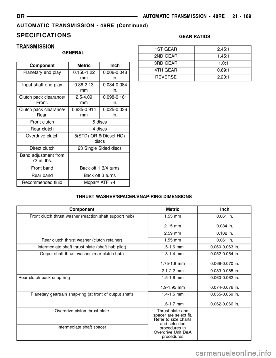
SPECIFICATIONS
TRANSMISSION
GENERAL
Component Metric Inch
Planetary end play 0.150-1.22
mm0.006-0.048
in.
Input shaft end play 0.86-2.13
mm0.034-0.084
in.
Clutch pack clearance/
Front.2.5-4.09
mm0.098-0.161
in.
Clutch pack clearance/
Rear.0.635-0.914
mm0.025-0.036
in.
Front clutch 5 discs
Rear clutch 4 discs
Overdrive clutch 5(STD) OR 6(Diesel HO)
discs
Direct clutch 23 Single Sided discs
Band adjustment from
72 in. lbs.
Front band Back off 1 3/4 turns
Rear band Back off 3 turns
Recommended fluid MoparTAT F + 4GEAR RATIOS
1ST GEAR 2.45:1
2ND GEAR 1.45:1
3RD GEAR 1.0:1
4TH GEAR 0.69:1
REVERSE 2.20:1
THRUST WASHER/SPACER/SNAP-RING DIMENSIONS
Component Metric Inch
Front clutch thrust washer (reaction shaft support hub) 1.55 mm 0.061 in.
2.15 mm 0.084 in.
2.59 mm 0.102 in.
Rear clutch thrust washer (clutch retainer) 1.55 mm 0.061 in.
Intermediate shaft thrust plate (shaft hub pilot) 1.5-1.6 mm 0.060-0.063 in.
Output shaft thrust washer (rear clutch hub) 1.3-1.4 mm 0.052-0.054 in.
1.75-1.8 mm 0.068-0.070 in.
2.1-2.2 mm 0.083-0.085 in.
Rear clutch pack snap-ring 1.5-1.6 mm 0.060-0.062 in.
1.9-1.95 mm 0.074-0.076 in.
Planetary geartrain snap-ring (at front of output shaft) 1.4-1.5 mm 0.055-0.059 in.
1.6-1.7 mm 0.062-0.066 in.
Overdrive piston thrust plate Thrust plate and
spacer are select fit.
Refer to size charts
and selection
procedures in
Overdrive Unit D&A
procedures Intermediate shaft spacer
DRAUTOMATIC TRANSMISSION - 48RE 21 - 189
AUTOMATIC TRANSMISSION - 48RE (Continued)
Page 1912 of 2627
DISASSEMBLY
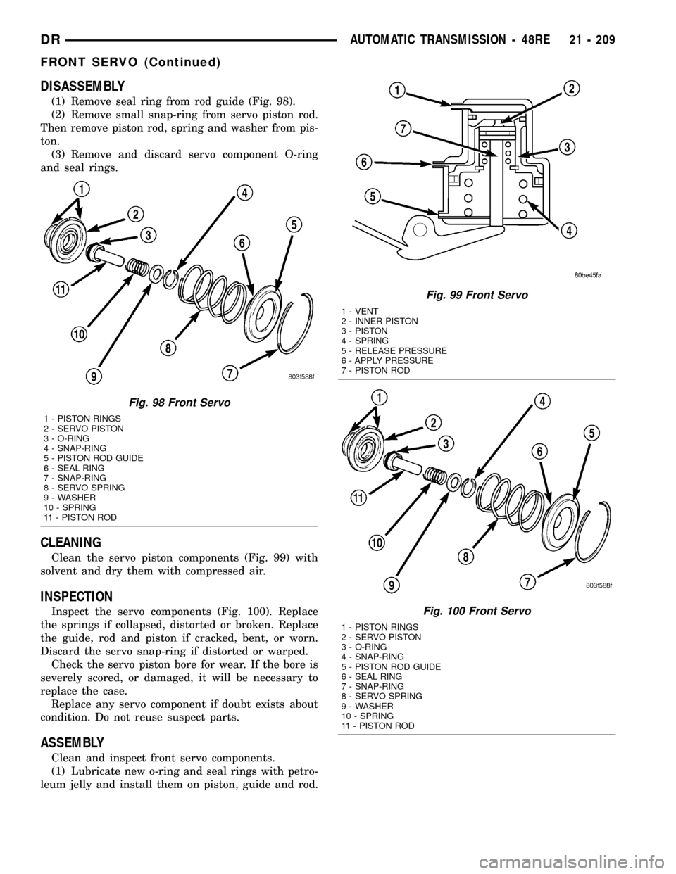
(1) Remove seal ring from rod guide (Fig. 98).
(2) Remove small snap-ring from servo piston rod.
Then remove piston rod, spring and washer from pis-
ton.
(3) Remove and discard servo component O-ring
and seal rings.
CLEANING
Clean the servo piston components (Fig. 99) with
solvent and dry them with compressed air.
INSPECTION
Inspect the servo components (Fig. 100). Replace
the springs if collapsed, distorted or broken. Replace
the guide, rod and piston if cracked, bent, or worn.
Discard the servo snap-ring if distorted or warped.
Check the servo piston bore for wear. If the bore is
severely scored, or damaged, it will be necessary to
replace the case.
Replace any servo component if doubt exists about
condition. Do not reuse suspect parts.
ASSEMBLY
Clean and inspect front servo components.
(1) Lubricate new o-ring and seal rings with petro-
leum jelly and install them on piston, guide and rod.
Fig. 98 Front Servo
1 - PISTON RINGS
2 - SERVO PISTON
3 - O-RING
4 - SNAP-RING
5 - PISTON ROD GUIDE
6 - SEAL RING
7 - SNAP-RING
8 - SERVO SPRING
9 - WASHER
10 - SPRING
11 - PISTON ROD
Fig. 99 Front Servo
1 - VENT
2 - INNER PISTON
3 - PISTON
4 - SPRING
5 - RELEASE PRESSURE
6 - APPLY PRESSURE
7 - PISTON ROD
Fig. 100 Front Servo
1 - PISTON RINGS
2 - SERVO PISTON
3 - O-RING
4 - SNAP-RING
5 - PISTON ROD GUIDE
6 - SEAL RING
7 - SNAP-RING
8 - SERVO SPRING
9 - WASHER
10 - SPRING
11 - PISTON ROD
DRAUTOMATIC TRANSMISSION - 48RE 21 - 209
FRONT SERVO (Continued)
Page 1913 of 2627
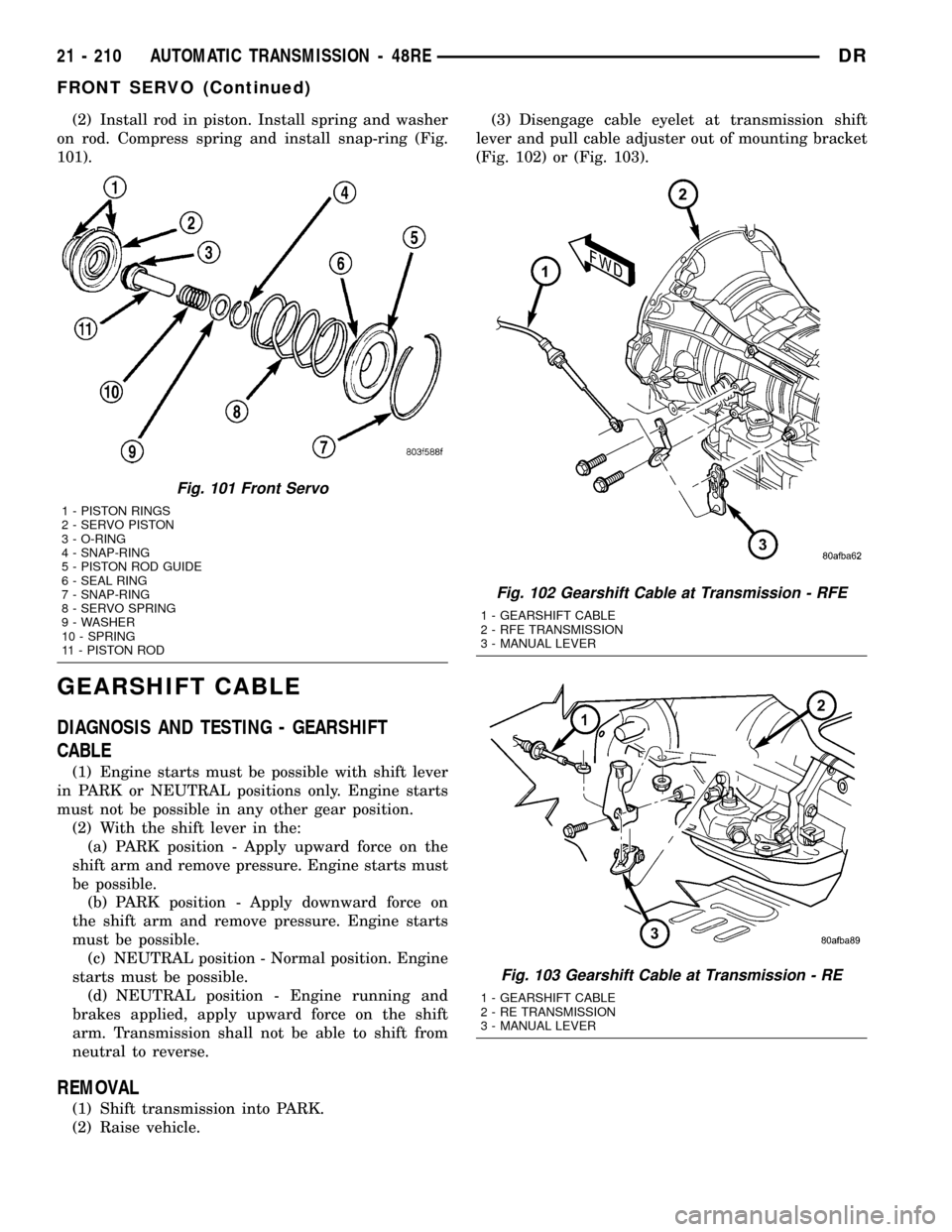
(2) Install rod in piston. Install spring and washer
on rod. Compress spring and install snap-ring (Fig.
101).
GEARSHIFT CABLE
DIAGNOSIS AND TESTING - GEARSHIFT
CABLE
(1) Engine starts must be possible with shift lever
in PARK or NEUTRAL positions only. Engine starts
must not be possible in any other gear position.
(2) With the shift lever in the:
(a) PARK position - Apply upward force on the
shift arm and remove pressure. Engine starts must
be possible.
(b) PARK position - Apply downward force on
the shift arm and remove pressure. Engine starts
must be possible.
(c) NEUTRAL position - Normal position. Engine
starts must be possible.
(d) NEUTRAL position - Engine running and
brakes applied, apply upward force on the shift
arm. Transmission shall not be able to shift from
neutral to reverse.
REMOVAL
(1) Shift transmission into PARK.
(2) Raise vehicle.(3) Disengage cable eyelet at transmission shift
lever and pull cable adjuster out of mounting bracket
(Fig. 102) or (Fig. 103).
Fig. 101 Front Servo
1 - PISTON RINGS
2 - SERVO PISTON
3 - O-RING
4 - SNAP-RING
5 - PISTON ROD GUIDE
6 - SEAL RING
7 - SNAP-RING
8 - SERVO SPRING
9 - WASHER
10 - SPRING
11 - PISTON ROD
Fig. 102 Gearshift Cable at Transmission - RFE
1 - GEARSHIFT CABLE
2 - RFE TRANSMISSION
3 - MANUAL LEVER
Fig. 103 Gearshift Cable at Transmission - RE
1 - GEARSHIFT CABLE
2 - RE TRANSMISSION
3 - MANUAL LEVER
21 - 210 AUTOMATIC TRANSMISSION - 48REDR
FRONT SERVO (Continued)
Page 1916 of 2627
OIL PUMP
DESCRIPTION
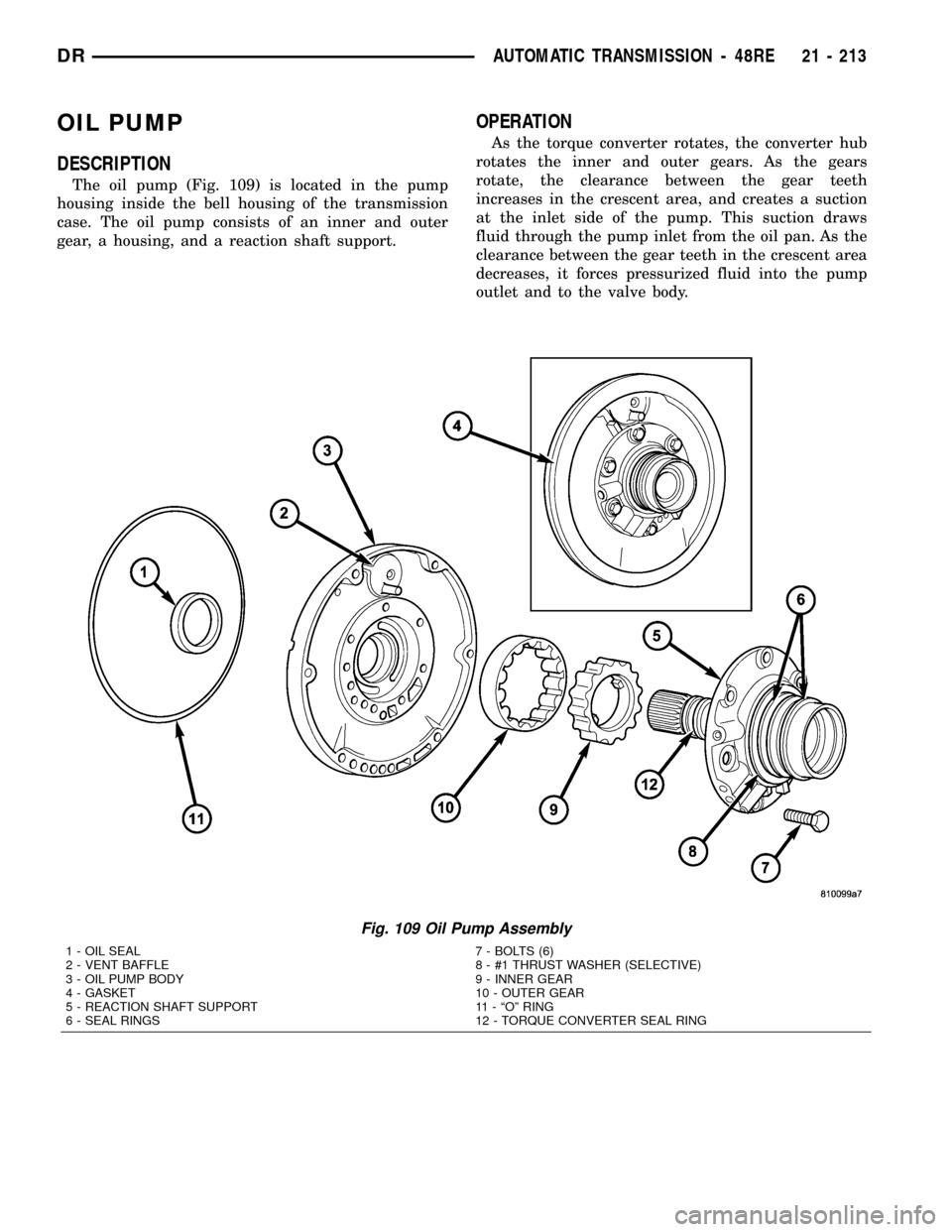
The oil pump (Fig. 109) is located in the pump
housing inside the bell housing of the transmission
case. The oil pump consists of an inner and outer
gear, a housing, and a reaction shaft support.
OPERATION
As the torque converter rotates, the converter hub
rotates the inner and outer gears. As the gears
rotate, the clearance between the gear teeth
increases in the crescent area, and creates a suction
at the inlet side of the pump. This suction draws
fluid through the pump inlet from the oil pan. As the
clearance between the gear teeth in the crescent area
decreases, it forces pressurized fluid into the pump
outlet and to the valve body.
Fig. 109 Oil Pump Assembly
1 - OIL SEAL 7 - BOLTS (6)
2 - VENT BAFFLE 8 - #1 THRUST WASHER (SELECTIVE)
3 - OIL PUMP BODY 9 - INNER GEAR
4 - GASKET 10 - OUTER GEAR
5 - REACTION SHAFT SUPPORT 11 - ªOº RING
6 - SEAL RINGS 12 - TORQUE CONVERTER SEAL RING
DRAUTOMATIC TRANSMISSION - 48RE 21 - 213
Page 1917 of 2627
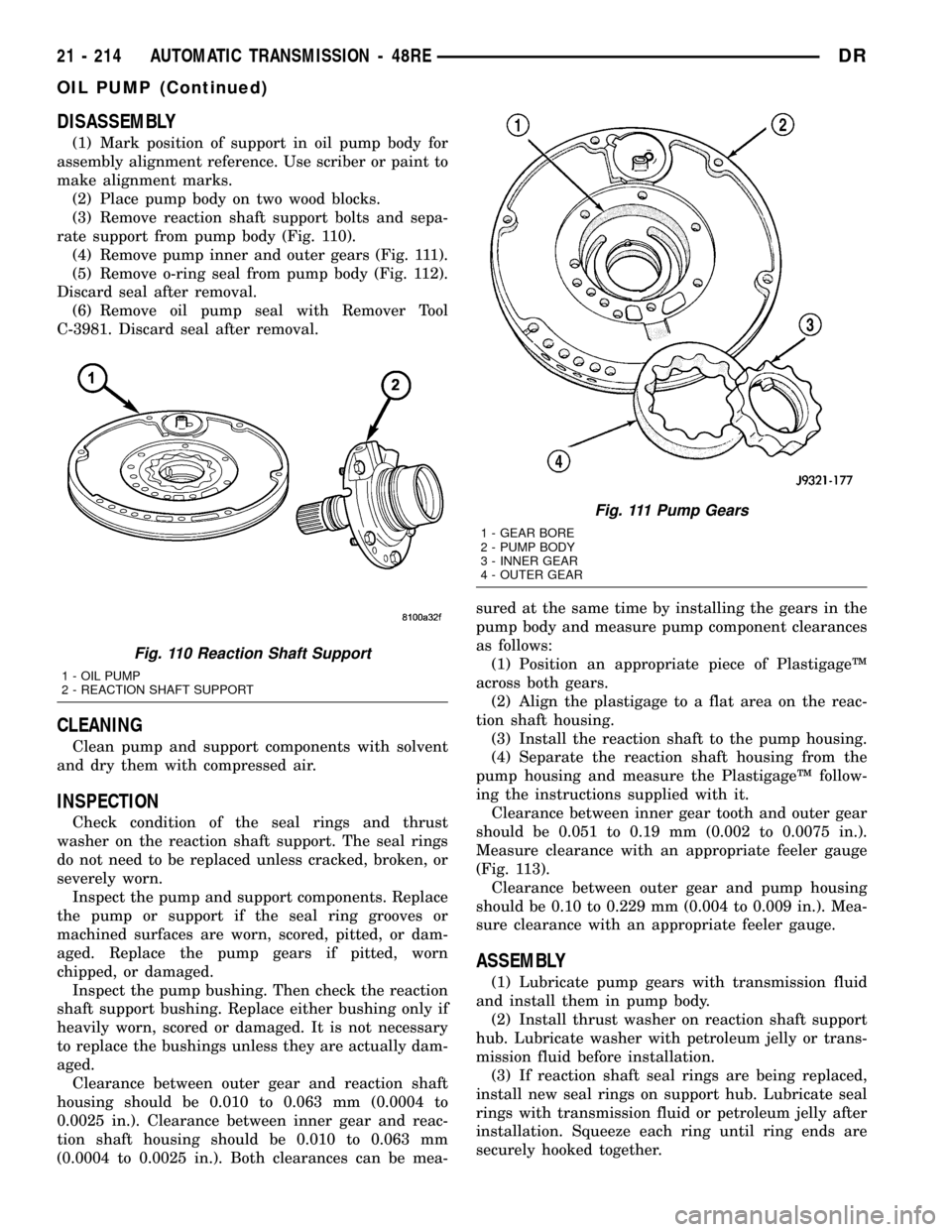
DISASSEMBLY
(1) Mark position of support in oil pump body for
assembly alignment reference. Use scriber or paint to
make alignment marks.
(2) Place pump body on two wood blocks.
(3) Remove reaction shaft support bolts and sepa-
rate support from pump body (Fig. 110).
(4) Remove pump inner and outer gears (Fig. 111).
(5) Remove o-ring seal from pump body (Fig. 112).
Discard seal after removal.
(6) Remove oil pump seal with Remover Tool
C-3981. Discard seal after removal.
CLEANING
Clean pump and support components with solvent
and dry them with compressed air.
INSPECTION
Check condition of the seal rings and thrust
washer on the reaction shaft support. The seal rings
do not need to be replaced unless cracked, broken, or
severely worn.
Inspect the pump and support components. Replace
the pump or support if the seal ring grooves or
machined surfaces are worn, scored, pitted, or dam-
aged. Replace the pump gears if pitted, worn
chipped, or damaged.
Inspect the pump bushing. Then check the reaction
shaft support bushing. Replace either bushing only if
heavily worn, scored or damaged. It is not necessary
to replace the bushings unless they are actually dam-
aged.
Clearance between outer gear and reaction shaft
housing should be 0.010 to 0.063 mm (0.0004 to
0.0025 in.). Clearance between inner gear and reac-
tion shaft housing should be 0.010 to 0.063 mm
(0.0004 to 0.0025 in.). Both clearances can be mea-sured at the same time by installing the gears in the
pump body and measure pump component clearances
as follows:
(1) Position an appropriate piece of PlastigageŸ
across both gears.
(2) Align the plastigage to a flat area on the reac-
tion shaft housing.
(3) Install the reaction shaft to the pump housing.
(4) Separate the reaction shaft housing from the
pump housing and measure the PlastigageŸ follow-
ing the instructions supplied with it.
Clearance between inner gear tooth and outer gear
should be 0.051 to 0.19 mm (0.002 to 0.0075 in.).
Measure clearance with an appropriate feeler gauge
(Fig. 113).
Clearance between outer gear and pump housing
should be 0.10 to 0.229 mm (0.004 to 0.009 in.). Mea-
sure clearance with an appropriate feeler gauge.
ASSEMBLY
(1) Lubricate pump gears with transmission fluid
and install them in pump body.
(2) Install thrust washer on reaction shaft support
hub. Lubricate washer with petroleum jelly or trans-
mission fluid before installation.
(3) If reaction shaft seal rings are being replaced,
install new seal rings on support hub. Lubricate seal
rings with transmission fluid or petroleum jelly after
installation. Squeeze each ring until ring ends are
securely hooked together.
Fig. 110 Reaction Shaft Support
1 - OIL PUMP
2 - REACTION SHAFT SUPPORT
Fig. 111 Pump Gears
1 - GEAR BORE
2 - PUMP BODY
3 - INNER GEAR
4 - OUTER GEAR
21 - 214 AUTOMATIC TRANSMISSION - 48REDR
OIL PUMP (Continued)
Page 1918 of 2627
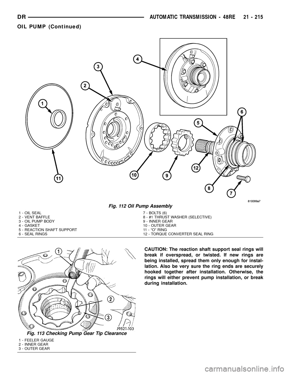
CAUTION: The reaction shaft support seal rings will
break if overspread, or twisted. If new rings are
being installed, spread them only enough for instal-
lation. Also be very sure the ring ends are securely
hooked together after installation. Otherwise, the
rings will either prevent pump installation, or break
during installation.
Fig. 112 Oil Pump Assembly
1 - OIL SEAL 7 - BOLTS (6)
2 - VENT BAFFLE 8 - #1 THRUST WASHER (SELECTIVE)
3 - OIL PUMP BODY 9 - INNER GEAR
4 - GASKET 10 - OUTER GEAR
5 - REACTION SHAFT SUPPORT 11 - ªOº RING
6 - SEAL RINGS 12 - TORQUE CONVERTER SEAL RING
Fig. 113 Checking Pump Gear Tip Clearance
1 - FEELER GAUGE
2 - INNER GEAR
3 - OUTER GEAR
DRAUTOMATIC TRANSMISSION - 48RE 21 - 215
OIL PUMP (Continued)
Page 1945 of 2627
DISASSEMBLY
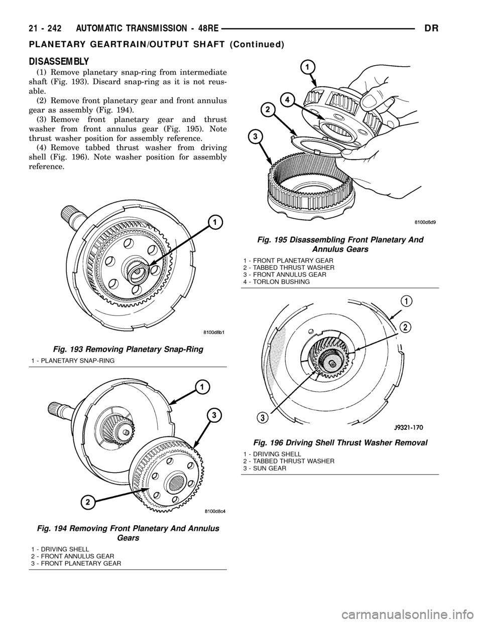
(1) Remove planetary snap-ring from intermediate
shaft (Fig. 193). Discard snap-ring as it is not reus-
able.
(2) Remove front planetary gear and front annulus
gear as assembly (Fig. 194).
(3) Remove front planetary gear and thrust
washer from front annulus gear (Fig. 195). Note
thrust washer position for assembly reference.
(4) Remove tabbed thrust washer from driving
shell (Fig. 196). Note washer position for assembly
reference.
Fig. 193 Removing Planetary Snap-Ring
1 - PLANETARY SNAP-RING
Fig. 194 Removing Front Planetary And Annulus
Gears
1 - DRIVING SHELL
2 - FRONT ANNULUS GEAR
3 - FRONT PLANETARY GEAR
Fig. 195 Disassembling Front Planetary And
Annulus Gears
1 - FRONT PLANETARY GEAR
2 - TABBED THRUST WASHER
3 - FRONT ANNULUS GEAR
4 - TORLON BUSHING
Fig. 196 Driving Shell Thrust Washer Removal
1 - DRIVING SHELL
2 - TABBED THRUST WASHER
3 - SUN GEAR
21 - 242 AUTOMATIC TRANSMISSION - 48REDR
PLANETARY GEARTRAIN/OUTPUT SHAFT (Continued)
Page 1946 of 2627
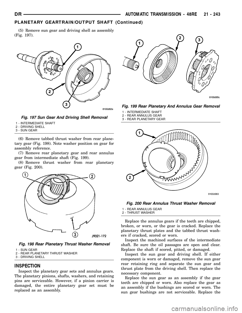
(5) Remove sun gear and driving shell as assembly
(Fig. 197).
(6) Remove tabbed thrust washer from rear plane-
tary gear (Fig. 198). Note washer position on gear for
assembly reference.
(7) Remove rear planetary gear and rear annulus
gear from intermediate shaft (Fig. 199).
(8) Remove thrust washer from rear planetary
gear (Fig. 200).
INSPECTION
Inspect the planetary gear sets and annulus gears.
The planetary pinions, shafts, washers, and retaining
pins are serviceable. However, if a pinion carrier is
damaged, the entire planetary gear set must be
replaced as an assembly.Replace the annulus gears if the teeth are chipped,
broken, or worn, or the gear is cracked. Replace the
planetary thrust plates and the tabbed thrust wash-
ers if cracked, scored or worn.
Inspect the machined surfaces of the intermediate
shaft. Be sure the oil passages are open and clear.
Replace the shaft if scored, pitted, or damaged.
Inspect the sun gear and driving shell. If either
component is worn or damaged, remove the sun gear
rear retaining ring and separate the sun gear and
thrust plate from the driving shell. Then replace the
necessary component.
Replace the sun gear as an assembly if the gear
teeth are chipped or worn. Also replace the gear as
an assembly if the bushings are scored or worn. The
sun gear bushings are not serviceable. Replace the
Fig. 197 Sun Gear And Driving Shell Removal
1 - INTERMEDIATE SHAFT
2 - DRIVING SHELL
3 - SUN GEAR
Fig. 198 Rear Planetary Thrust Washer Removal
1 - SUN GEAR
2 - REAR PLANETARY THRUST WASHER
3 - DRIVING SHELL
Fig. 199 Rear Planetary And Annulus Gear Removal
1 - INTERMEDIATE SHAFT
2 - REAR ANNULUS GEAR
3 - REAR PLANETARY GEAR
Fig. 200 Rear Annulus Thrust Washer Removal
1 - REAR ANNULUS GEAR
2 - THRUST WASHER
DRAUTOMATIC TRANSMISSION - 48RE 21 - 243
PLANETARY GEARTRAIN/OUTPUT SHAFT (Continued)