1998 DODGE RAM 1500 Washer
[x] Cancel search: WasherPage 1006 of 2627

8W-53 WIPERS
Component Page
Data Link Connector................. 8W-53-2
Front Control Module............. 8W-53-2, 3, 4
Fuse 8............................ 8W-53-3
G104............................ 8W-53-3, 4
G105.............................. 8W-53-4
Instrument Cluster................... 8W-53-2
Integrated Power Module.......... 8W-53-2, 3, 4Component Page
Multi-Function Switch................ 8W-53-2
Washer Fluid Level Switch............. 8W-53-4
Washer Pump Motor-Front............. 8W-53-4
Wiper High/Low Relay.............. 8W-53-3, 4
Wiper Motor-Front................. 8W-53-3, 4
Wiper On/Off Relay.................. 8W-53-3
DR8W-53 WIPERS 8W - 53 - 1
Page 1053 of 2627

Component Page
Speaker-Right Instrument Panel....... 8W-80-96
Speaker-Right Rear................. 8W-80-96
Speed Control Servo (Diesel A/T/NGC) . . . 8W-80-97
Speed Control Switch-Left (ETC)....... 8W-80-97
Speed Control Switch-Left
(Except ETC).................... 8W-80-97
Speed Control Switch-Right (ETC)...... 8W-80-97
Speed Control Switch-Right (Except
ETC)........................... 8W-80-97
Tail/Stop/Turn Signal Lamp-Left....... 8W-80-98
Tail/Stop/Turn Signal Lamp-Right...... 8W-80-98
Tailgate Lamp..................... 8W-80-98
Throttle Position Sensor (3.7L)......... 8W-80-98
Throttle Position Sensor (4.7L)......... 8W-80-99
Tow/haul Overdrive Switch............ 8W-80-99
Trailer Tow Connector............... 8W-80-99
Trailer Tow Connector-Add On......... 8W-80-99
Transfer Case Control Module C1 (Electric
4x4).......................... 8W-80-100
Transfer Case Control Module C2 (Electric
4x4).......................... 8W-80-100Component Page
Transfer Case Control Module C3
(Electric 4x4)................... 8W-80-101
Transfer Case Mode Sensor.......... 8W-80-101
Transfer Case Selector Switch........ 8W-80-101
Transfer Case Shift Motor........... 8W-80-101
Transmission Range Sensor.......... 8W-80-102
Transmission Solenoid Assembly
(48RE)........................ 8W-80-102
Transmission Solenoid/TRS Assembly
(NGC)......................... 8W-80-102
Vacuum Pump (Diesel).............. 8W-80-103
Vistronic Fan Drive (Diesel).......... 8W-80-103
Washer Fluid Level Switch........... 8W-80-103
Washer Pump Motor-Front........... 8W-80-103
Water In Fuel Sensor............... 8W-80-103
Wheel Speed Sensor-Left Front....... 8W-80-104
Wheel Speed Sensor-Rear............ 8W-80-104
Wheel Speed Sensor-Right Front...... 8W-80-104
Wiper Motor...................... 8W-80-104
8W - 80 - 4 8W-80 CONNECTOR PIN-OUTSDR
Page 1123 of 2627
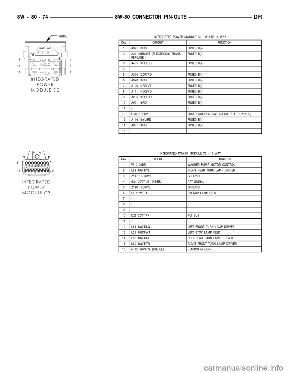
INTEGRATED POWER MODULE C2 - WHITE 15 WAY
CAV CIRCUIT FUNCTION
1 A991 10RD FUSED B(+)
2 A34 16RD/WT (ELECTRONIC TRANS-
FERCASE))FUSED B(+)
3 A405 18RD/DB FUSED B(+)
4- -
5 A210 12OR/RD FUSED B(+)
6 A970 10RD FUSED B(+)
7 A100 14RD/VT FUSED B(+)
8 A111 14DG/RD FUSED B(+)
9 A205 18RD/OR FUSED B(+)
10 A921 16RD FUSED B(+)
11 - -
12 F984 18PK/YL FUSED IGNITION SWITCH OUTPUT (RUN-ACC)
13 A116 18YL/RD FUSED B(+)
14 A951 16RD FUSED B(+)
15 - -
INTEGRATED POWER MODULE C3 - 16 WAY
CAV CIRCUIT FUNCTION
1 W10 20BR WASHER PUMP MOTOR CONTROL
2 L62 18WT/YL RIGHT REAR TURN LAMP DRIVER
3 Z117 18BK/WT GROUND
4 G31 20VT/LG (DIESEL) AAT SIGNAL
5 Z118 18BK/YL GROUND
6 L1 18WT/LG BACKUP LAMP FEED
7- -
8- -
9- -
10 D25 20VT/PK PCI BUS
11 - -
12 L61 18WT/LG LEFT FRONT TURN LAMP DRIVER
13 L53 18DG/WT LEFT STOP LAMP FEED
14 L63 18WT/DG LEFT REAR TURN LAMP DRIVER
15 L60 18WT/TN RIGHT FRONT TURN LAMP DRIVER
16 G180 20VT/YL (DIESEL) SENSOR GROUND
8W - 80 - 74 8W-80 CONNECTOR PIN-OUTSDR
Page 1124 of 2627
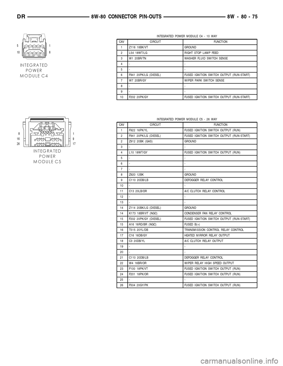
INTEGRATED POWER MODULE C4 - 10 WAY
CAV CIRCUIT FUNCTION
1 Z116 18BK/VT GROUND
2 L54 18WT/LG RIGHT STOP LAMP FEED
3 W1 20BR/TN WASHER FLUID SWITCH SENSE
4- -
5- -
6 F941 20PK/LG (DIESEL) FUSED IGNITION SWITCH OUTPUT (RUN-START)
7 W7 20BR/GY WIPER PARK SWITCH SENSE
8- -
9- -
10 F202 20PK/GY FUSED IGNITION SWITCH OUTPUT (RUN-START)
INTEGRATED POWER MODULE C5 - 26 WAY
CAV CIRCUIT FUNCTION
1 F922 16PK/YL FUSED IGNITION SWITCH OUTPUT (RUN)
2 F941 20PK/LG (DIESEL) FUSED IGNITION SWITCH OUTPUT (RUN-START)
2 Z912 20BK (GAS) GROUND
3- -
4 L10 18WT/GY FUSED IGNITION SWITCH OUTPUT (RUN)
5- -
6- -
7- -
8 Z920 12BK GROUND
9 C110 20DB/LB DEFOGGER RELAY CONTROL
10 - -
11 C13 20LB/OR A/C CLUTCH RELAY CONTROL
12 - -
13 - -
14 Z114 20BK/LG (DIESEL) GROUND
14 K173 18BR/VT (NGC) CONDENSER FAN RELAY CONTROL
15 F202 20PK/GY (DIESEL) FUSED IGNITION SWITCH OUTPUT (RUN-START)
15 A16 16RD/BR (NGC) FUSED B(+)
16 T515 20YL/DB TRANSMISSION CONTROL RELAY CONTROL
17 C16 16DB/GY HEATED MIRROR RELAY OUTPUT
18 C3 20DB/YL A/C CLUTCH RELAY OUTPUT
19 - -
20 - -
21 C110 20DB/LB DEFOGGER RELAY CONTROL
22 W4 16BR/OR WIPER RELAY HIGH SPEED OUTPUT
23 F100 18PK/VT FUSED IGNITION SWITCH OUTPUT (RUN)
24 F201 18PK/OR FUSED IGNITION SWITCH OUTPUT (RUN)
25 - -
26 F504 20GY/PK FUSED IGNITION SWITCH OUTPUT (RUN)
DR8W-80 CONNECTOR PIN-OUTS 8W - 80 - 75
Page 1152 of 2627
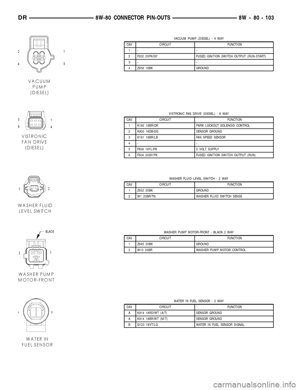
VACUUM PUMP (DIESEL)-4WAY
CAV CIRCUIT FUNCTION
1- -
2 F202 20PK/GY FUSED IGNITION SWITCH OUTPUT (RUN-START)
3- -
4 Z936 18BK GROUND
VISTRONIC FAN DRIVE (DIESEL)-6WAY
CAV CIRCUIT FUNCTION
1 K160 18BR/OR PARK LOCKOUT SOLENOID CONTROL
2 K900 18DB/DG SENSOR GROUND
3 K161 18BR/LB FAN SPEED SENSOR
4- -
5 F856 18YL/PK 5 VOLT SUPPLY
6 F504 20GY/PK FUSED IGNITION SWITCH OUTPUT (RUN)
WASHER FLUID LEVEL SWITCH-2WAY
CAV CIRCUIT FUNCTION
1 Z932 20BK GROUND
2 W1 20BR/TN WASHER FLUID SWITCH SENSE
WASHER PUMP MOTOR-FRONT - BLACK 2 WAY
CAV CIRCUIT FUNCTION
1 Z945 20BK GROUND
2 W10 20BR WASHER PUMP MOTOR CONTROL
WATER IN FUEL SENSOR-2WAY
CAV CIRCUIT FUNCTION
A K914 18RD/WT (A/T) SENSOR GROUND
A K914 18BR/WT (M/T) SENSOR GROUND
B G123 18VT/LG WATER IN FUEL SENSOR SIGNAL
DR8W-80 CONNECTOR PIN-OUTS 8W - 80 - 103
Page 1161 of 2627
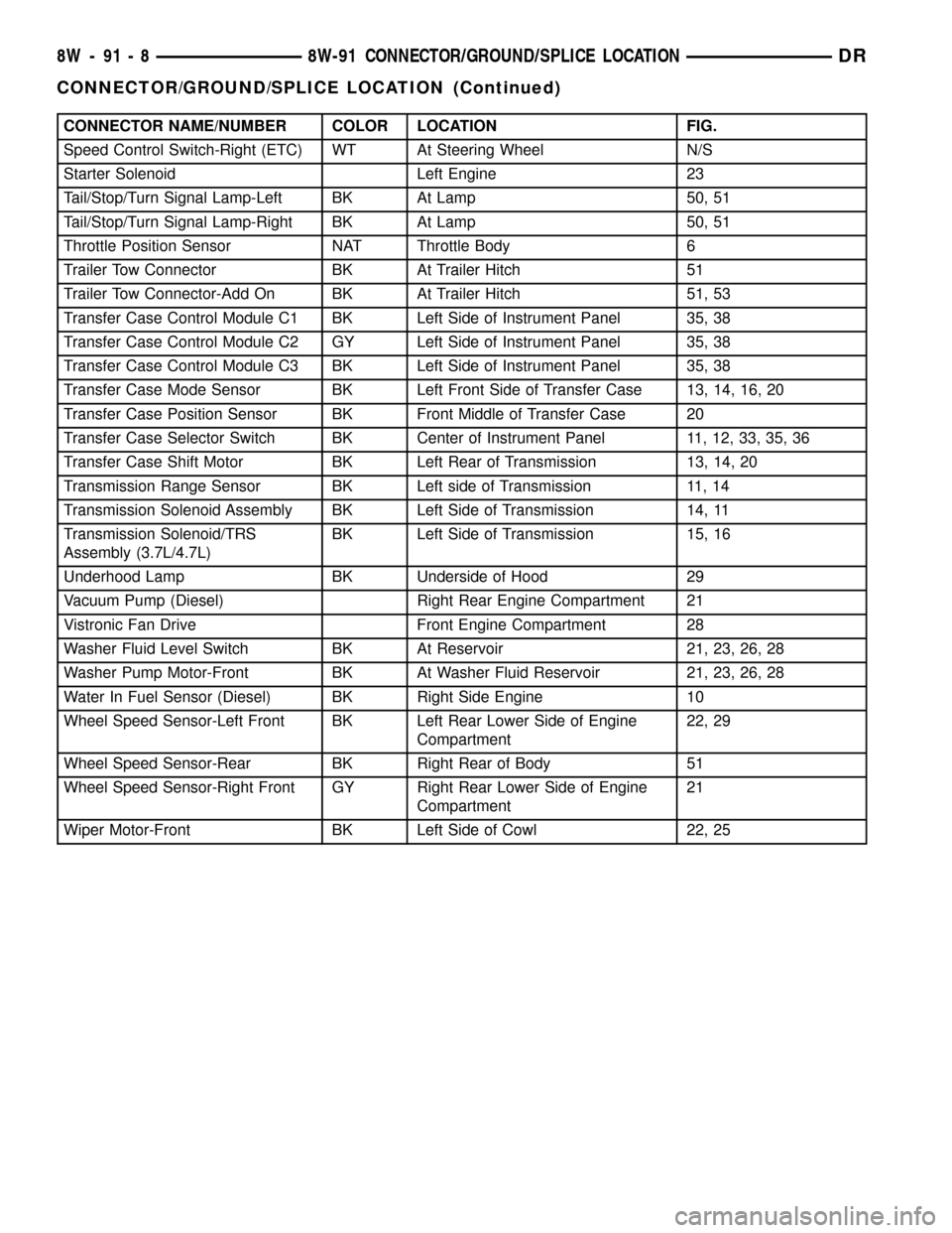
CONNECTOR NAME/NUMBER COLOR LOCATION FIG.
Speed Control Switch-Right (ETC) WT At Steering Wheel N/S
Starter Solenoid Left Engine 23
Tail/Stop/Turn Signal Lamp-Left BK At Lamp 50, 51
Tail/Stop/Turn Signal Lamp-Right BK At Lamp 50, 51
Throttle Position Sensor NAT Throttle Body 6
Trailer Tow Connector BK At Trailer Hitch 51
Trailer Tow Connector-Add On BK At Trailer Hitch 51, 53
Transfer Case Control Module C1 BK Left Side of Instrument Panel 35, 38
Transfer Case Control Module C2 GY Left Side of Instrument Panel 35, 38
Transfer Case Control Module C3 BK Left Side of Instrument Panel 35, 38
Transfer Case Mode Sensor BK Left Front Side of Transfer Case 13, 14, 16, 20
Transfer Case Position Sensor BK Front Middle of Transfer Case 20
Transfer Case Selector Switch BK Center of Instrument Panel 11, 12, 33, 35, 36
Transfer Case Shift Motor BK Left Rear of Transmission 13, 14, 20
Transmission Range Sensor BK Left side of Transmission 11, 14
Transmission Solenoid Assembly BK Left Side of Transmission 14, 11
Transmission Solenoid/TRS
Assembly (3.7L/4.7L)BK Left Side of Transmission 15, 16
Underhood Lamp BK Underside of Hood 29
Vacuum Pump (Diesel) Right Rear Engine Compartment 21
Vistronic Fan Drive Front Engine Compartment 28
Washer Fluid Level Switch BK At Reservoir 21, 23, 26, 28
Washer Pump Motor-Front BK At Washer Fluid Reservoir 21, 23, 26, 28
Water In Fuel Sensor (Diesel) BK Right Side Engine 10
Wheel Speed Sensor-Left Front BK Left Rear Lower Side of Engine
Compartment22, 29
Wheel Speed Sensor-Rear BK Right Rear of Body 51
Wheel Speed Sensor-Right Front GY Right Rear Lower Side of Engine
Compartment21
Wiper Motor-Front BK Left Side of Cowl 22, 25
8W - 91 - 8 8W-91 CONNECTOR/GROUND/SPLICE LOCATIONDR
CONNECTOR/GROUND/SPLICE LOCATION (Continued)
Page 1220 of 2627

(3) Connect the electrical connectors by pushing
straight on and rotating the connector arm inboard,
until the connector is firmly locked in place on the
module assembly.
(4) Grasp the integrated power module with two
hands and install the assembly on the battery tray
(Fig. 5).
(5) Install the integrated power module retaining
bolt and screw.
(6) Connect the gray connector on the integrated
power module housing.
(7) Install the B+ terminal cable and nut on the
integrated power module B+ terminal. Snap the
cover in place.
(8) Connect the negative and positive battery
cables.
FRONT CONTROL MODULE
DESCRIPTION
The Front Control Module (FCM) is a micro con-
troller based module located in the left front corner
of the engine compartment. On this model the inte-
grated power module must be positioned aside in
order to access the front control module. The front
control module mates to the power distribution cen-
ter to form the Integrated Power Module (IPM). Theintegrated power module connects directly to the bat-
tery and provides the primary means of circuit pro-
tection and power distribution for all vehicle
electrical systems. The front control module controls
power to some of these vehicle systems electrical and
electromechanical loads based on inputs received
from hard wired switch inputs and data received on
the PCI bus circuit (J1850).
For information on theIntegrated Power Mod-
ule Refer to the Power Distribution Sectionof
the service manual.
OPERATION
As messages are sent over the PCI bus circuit, the
front control module reads these messages and con-
trols power to some of the vehicles electrical systems
by completing the circuit to ground (low side driver)
or completing the circuit to 12 volt power (high side
driver). The following functions areControlledby
the Front Control Module:
²Headlamp Power with Voltage Regulation
²Windshield Wiper ªON/OFFº Relay Actuation
²Windshield Wiper ªHI/LOº Relay Actuation
²Windshield Washer Pump Motor
²Fog Lamp Relay Actuation
²Park Lamp Relay Actuation
²Horn Relay Actuation
The following inputs areReceived/Monitoredby
the Front Control Module:
²B+ Connection Detection
²Power Ground
²Ambient Temperature Sensing
²Ignition Switch Run
²Washer Fluid Level Switch
²Windshield Wiper Park Switch
²PCI Bus Circuit
DIAGNOSIS AND TESTING - FRONT CONTROL
MODULE
The front control module is a printed circuit board
based module with a on-board micro-processor. The
front control module interfaces with other electronic
modules in the vehicle via the Programmable Com-
munications Interface (PCI) data bus (J1850). In
order to obtain conclusive testing the Programmable
Communications Interface (PCI) data bus network
and all of the electronic modules that provide inputs
to, or receive outputs from the front control module
must be checked. All PCI (J1850) communication
faults must be resolved prior to further diagnosing
any front control module related issues.
The front control module was designed to be diag-
nosed with an appropriate diagnostic scan tool, such
as the DRB IIIt. The most reliable, efficient, and
accurate means to diagnose the front control module
Fig. 5 INTEGRATED POWER MODULE MOUNTING
TABS
1 - INTEGRATED POWER MODULE MOUNTING HOLES
2 - BATTERY TRAY ASSEMBLY
3 - FRONT CONTROL MODULE
DR8W-97 POWER DISTRIBUTION 8W - 97 - 5
INTEGRATED POWER MODULE (Continued)
Page 1229 of 2627
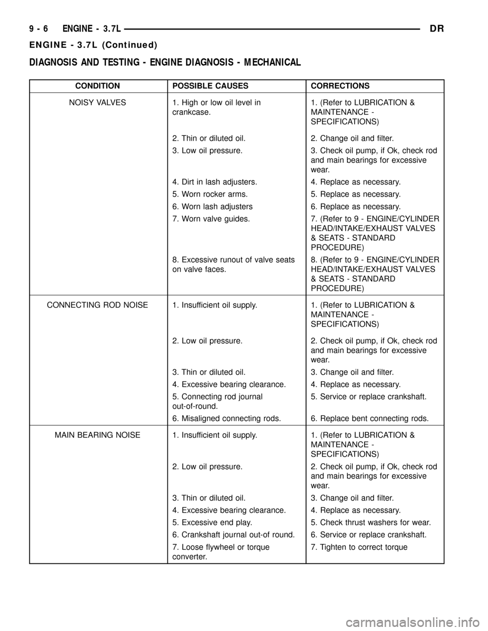
DIAGNOSIS AND TESTING - ENGINE DIAGNOSIS - MECHANICAL
CONDITION POSSIBLE CAUSES CORRECTIONS
NOISY VALVES 1. High or low oil level in
crankcase.1. (Refer to LUBRICATION &
MAINTENANCE -
SPECIFICATIONS)
2. Thin or diluted oil. 2. Change oil and filter.
3. Low oil pressure. 3. Check oil pump, if Ok, check rod
and main bearings for excessive
wear.
4. Dirt in lash adjusters. 4. Replace as necessary.
5. Worn rocker arms. 5. Replace as necessary.
6. Worn lash adjusters 6. Replace as necessary.
7. Worn valve guides. 7. (Refer to 9 - ENGINE/CYLINDER
HEAD/INTAKE/EXHAUST VALVES
& SEATS - STANDARD
PROCEDURE)
8. Excessive runout of valve seats
on valve faces.8. (Refer to 9 - ENGINE/CYLINDER
HEAD/INTAKE/EXHAUST VALVES
& SEATS - STANDARD
PROCEDURE)
CONNECTING ROD NOISE 1. Insufficient oil supply. 1. (Refer to LUBRICATION &
MAINTENANCE -
SPECIFICATIONS)
2. Low oil pressure. 2. Check oil pump, if Ok, check rod
and main bearings for excessive
wear.
3. Thin or diluted oil. 3. Change oil and filter.
4. Excessive bearing clearance. 4. Replace as necessary.
5. Connecting rod journal
out-of-round.5. Service or replace crankshaft.
6. Misaligned connecting rods. 6. Replace bent connecting rods.
MAIN BEARING NOISE 1. Insufficient oil supply. 1. (Refer to LUBRICATION &
MAINTENANCE -
SPECIFICATIONS)
2. Low oil pressure. 2. Check oil pump, if Ok, check rod
and main bearings for excessive
wear.
3. Thin or diluted oil. 3. Change oil and filter.
4. Excessive bearing clearance. 4. Replace as necessary.
5. Excessive end play. 5. Check thrust washers for wear.
6. Crankshaft journal out-of round. 6. Service or replace crankshaft.
7. Loose flywheel or torque
converter.7. Tighten to correct torque
9 - 6 ENGINE - 3.7LDR
ENGINE - 3.7L (Continued)