Page 57 of 72

58
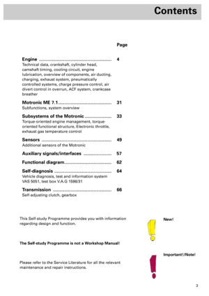
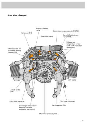
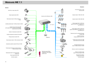
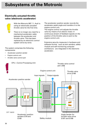
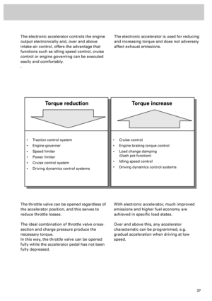
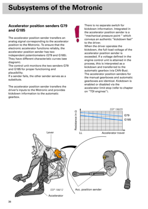
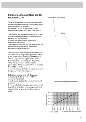
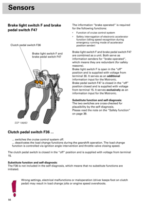
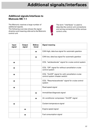
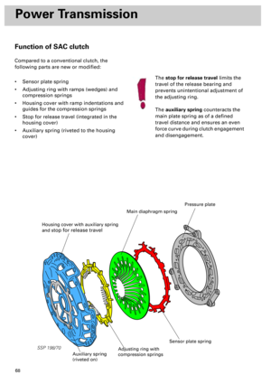
Additional signals/interfaces
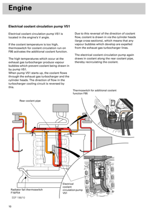
The road speed signal ...
... is required for operation of the cruise control
system, speed limiter, load change measures,
idling speed stabilisation and internal safety
checks of the control unit (e.g. adaption
conditions).... is a square-wave signal which is conditioned
by the dash panel insert. The frequency of this
signal changes as a factor of road speed.
The dash panel insert transfers 4 pulses per
revolution of the wheel.
Coolant temperature signal
The engine control unit receives from the dash
panel insert a coolant temperature signal
calculated from the signal which coolant
temperature sender G2 generates and a
related temperature characteristic.
The signal is a “data message“ and is
connected to the earth potential when a
temperature of approx. 120 °C is exceeded.
In this case, the air conditioner’s operating and
display unit switches the compressor off along
the bidirectional wire designated “Air-
conditioner compressor On/Off“.As of a temperature of 116 °C, the charge
pressure is reduced in order to counteract a
further rise in temperature.
If the temperature drops below a value of
approx. 116 °C, a data message is again
transferred and all actions previously
performed are reversed.
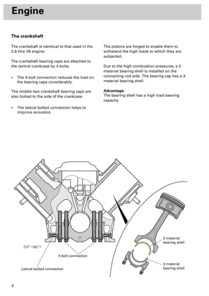
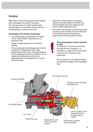
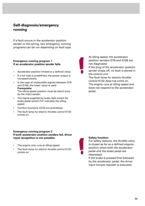
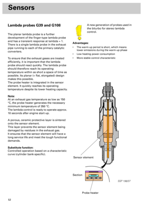
SSP 198/69
1 revolution of wheel Road speed signal (4 pulses)
Signal from speedometer sender (reed contact)
Page 58 of 72

59
The “Compressor On/Off“ interface ...
... serves to provide the engine control unit
with information on the circuit state of the
compressor.
... enables the engine control unit to switch off
the compressor or inhibit start-up.
... provides a link to the air conditioner’s
operating and display unit.
The interface as a signal input:
Shortly before switching on the magnetic
coupling, the air conditioner’s operating and
display unit applies voltage to the interface.
The engine control unit then increases the
idling speed to compensate for the higher
engine load.The interface as a signal output:
If the engine control unit applies an earth
potential to the interface, the compressor is
switched off for a defined period of time as
required.
The engine control unit switches the
compressor off in the following situations:
- After initiating basic setting (function 04)
- In certain emergency running programs
within a defined engine speed range
The immobiliser/diagnosis interface ...
... is the communication link between the
engine control unit and the immobiliser in the
dash panel insert.... also serves as the diagnosis wire (K-wire) for
the diagnosis tester. Dialogue takes place via:
diagnosis plug Û dash panel insert interface Û
immobiliser/diagnosis interface Û engine
control unit
Page 59 of 72
60
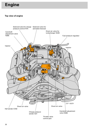
Additional signals/interface
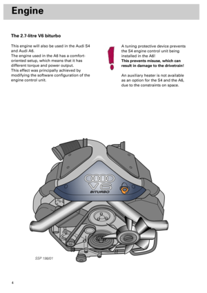
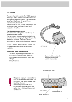
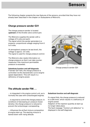
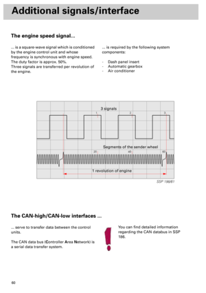
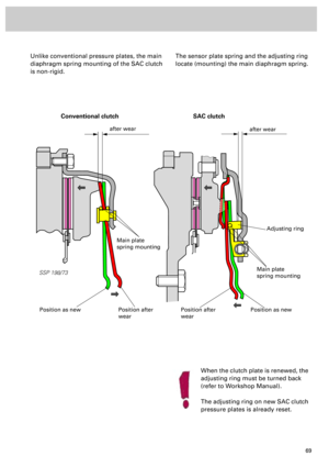
The engine speed signal...
... is a square-wave signal which is conditioned
by the engine control unit and whose
frequency is synchronous with engine speed.
The duty factor is approx. 50%.
Three signals are transferred per revolution of
the engine.... is required by the following system
components:
- Dash panel insert
- Automatic gearbox
- Air conditioner
The CAN-high/CAN-low interfaces ...
... serve to transfer data between the control
units.
The CAN data bus (Controller Area Network) is
a serial data transfer system.You can find detailed information
regarding the CAN databus in SSP
186.
12
20 40 603
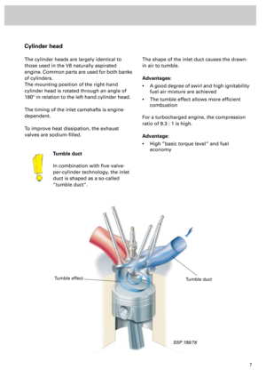
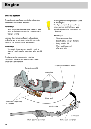
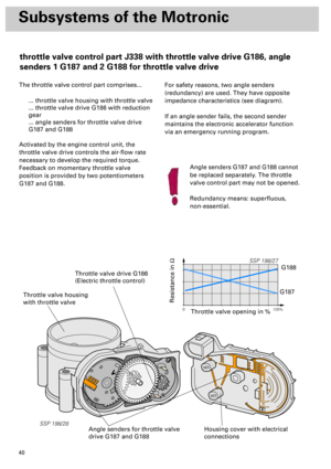
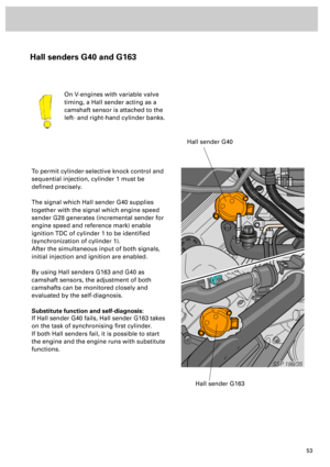
SSP 198/61
1 revolution of engineSegments of the sender wheel 3 signals
Page 60 of 72
61
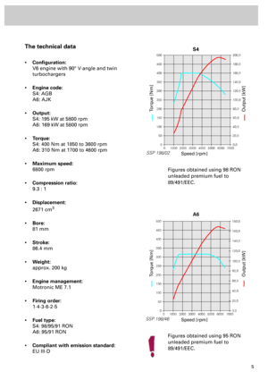
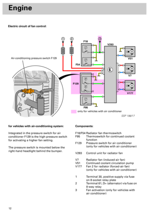
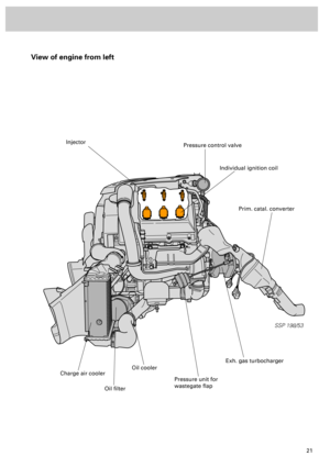
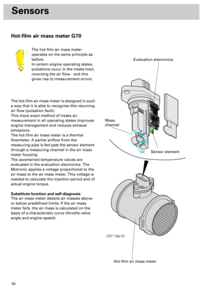
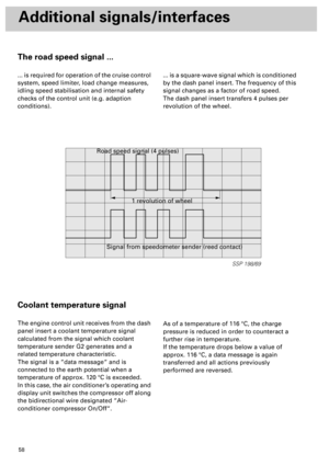
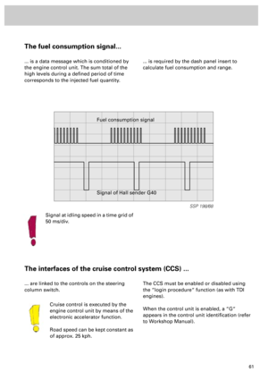
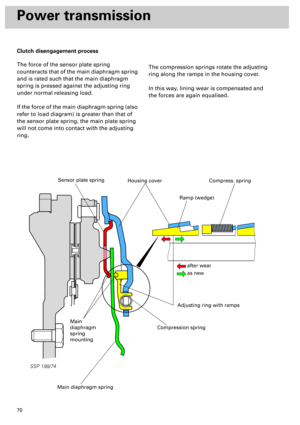
The fuel consumption signal...
... is a data message which is conditioned by
the engine control unit. The sum total of the
high levels during a defined period of time
corresponds to the injected fuel quantity.... is required by the dash panel insert to
calculate fuel consumption and range.
The interfaces of the cruise control system (CCS) ...
... are linked to the controls on the steering
column switch.
Cruise control is executed by the
engine control unit by means of the
electronic accelerator function.
Road speed can be kept constant as
of approx. 25 kph.The CCS must be enabled or disabled using
the “login procedure“ function (as with TDI
engines).
When the control unit is enabled, a “G“
appears in the control unit identification (refer
to Workshop Manual).
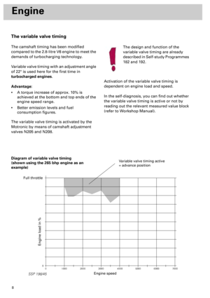
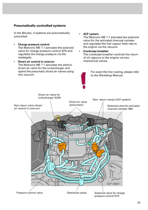
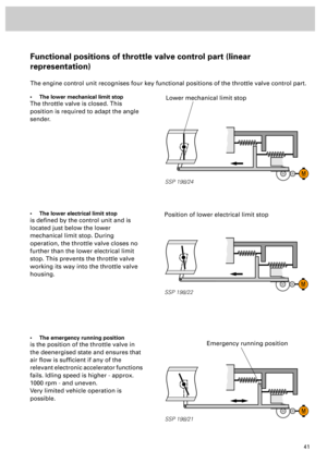
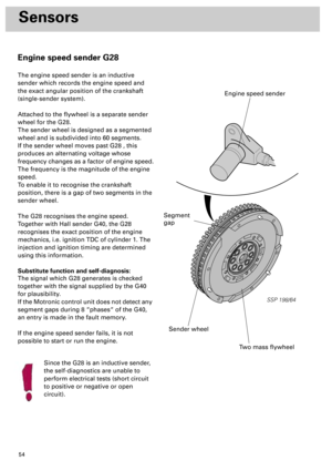
SSP 198/68
Fuel consumption signal
Signal of Hall sender G40
Signal at idling speed in a time grid of
50 ms/div.
Page 61 of 72

G2 Coolant temperature sender
G6 Fuel pum")
62
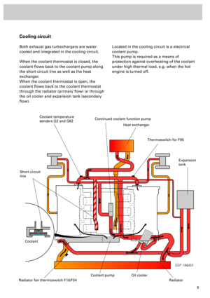
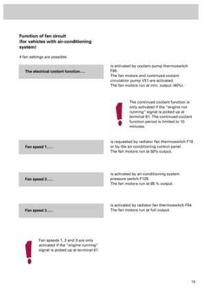
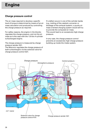
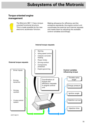
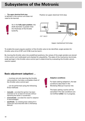
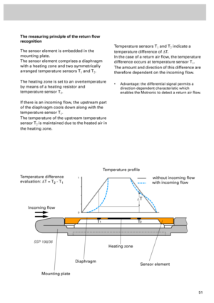
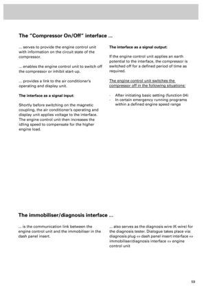
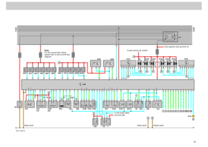
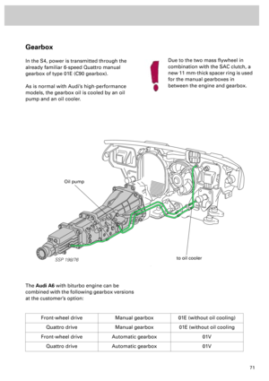
Functional diagram
Components:
F Brake light switch
F36 Clutch pedal switch
F47 Brake pedal switch
F96 Altitude sender (integrated in engine
control unit)
G2 Coolant temperature sender
G6 Fuel pump
G28 Engine speed sender
G31 Charge pressure sender
G39 Lambda probe (cylinder bank 1)
G40 Hall sender (cylinder bank 2)
G42 Intake air temperature sender
G 61 Knock sensor (cylinder bank 1)
G62 Coolant temperature sender
G66 Knock sensor (cylinder bank 2)
G70 Air mass meter
G79 Accelerator position sender 1
G108 Lambda probe (cylinder bank 2)
G163 Hall sender (cylinder bank 1)
G185 Accelerator position sender 2
G186 Throttle valve drive (electric throttle
control)
G187 Angle sender 1 for throttle valve drive
G188 Angle sender 2 for throttle valve drive
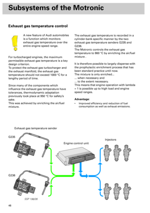
G235 Sender 1 for exhaust gas temperature
G236 Sender 2 for exhaust gas temperature
J17 Fuel pump relay
J220 Motronic control unit
J338 throttle valve control part
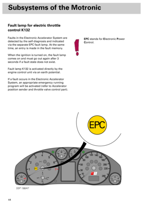
K132 Warning lamp for electric throttle
control
N Ignition coil, cylinder 1
N30 Injector, cylinder 1
N31 Injector, cylinder 2
N32 Injector, cylinder 3
N33 Injector , cylinder 4
N75 Solenoid valve for charge pressure
control
N80 Solenoid valve for activated charcoal
canister
N83 Injector, cylinder 5
N84 Injector, cylinder 6
N122 Output stage (cylinder bank 1)
N128 Ignition coil, cylinder 2
N158 Ignition coil, cylinder 3
N163 Ignition coil, cylinder 4
N164 Ignition coil, cylinder 5N189 Ignition coil, cylinder 6
N192 Output stage (cylinder bank 2)
N205 Camshaft adjustment valve 1 (cylinder
bank 1)
N208 Camshaft adjustment valve 2
(cylinder bank 2)
N249 Divert air valve for turbocharger
Z19 Heater for lambda probe
Z28 Heater for lambda probe 2
I To dash panel insert
II To dash panel insert (warning lamp)
Additional signals
1 CAN-high (automatic gearbox)
2 CAN-low (automatic gearbox)
3 „Set/decelerate“ signal for cruise
control system
4 “Off“ signal without cancellation for
cruise control system
5 “On/Off“ signal with cancellation for
cruise control system
6 Resume/accelerate“ signal for cruise
control system
7 Road speed signal
8 Immobiliser/diagnosis signal
9 Air conditioner compressor “On/Off“
signal
10 Coolant temperature signal
11 Engine speed signal
12 Fuel consumption signal
Colour codes:
Input signal
Output signal
Positive
Earth
Bidirectional
Page 62 of 72
63
M
30
15
31
31 31
30
15
31
_
G6N31
N32N33N80
J220
N83N84
N30
N75
N249
N205
N208
SSP 198/18
G235
G236
G31
N N128J17
N158 N163 N164 N189
Q PPPPPP
QQ QQQ
A
A
B Z
ZB
B
B
N122
A
B
B
B
1
N192
G61
G66 G188 G187 G186 G79
F47 F36 FG163 G40 G62G2 G42
K132 G185
G28 G70 G39
Z19G108
Z28
Y
+
Y
I
2
3
4
5
6
7
8
9
10
11
12
II
l
l
t° t°
m
lt° t° t°
+++ +
Cruise control op. switch
from ignition lock terminal 15
to the brake lightsterminal 30a
Body earth
Engine earth
Note:
For the correct fuse rating,
please refer to the current flow
diagram
Body earth
Page 63 of 72

64
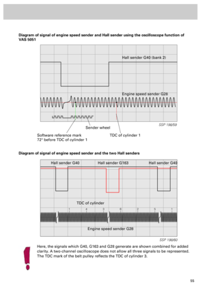
SSP 198/39
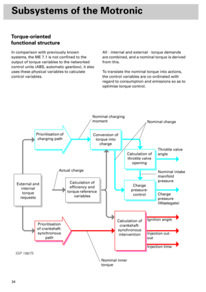
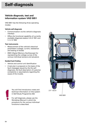
Self-diagnosis
Vehicle diagnosis, test and
information system VAS 5051
VAS 5051 has the following three operating
modes:
Vehicle self-diagnosis
• Communication via the vehicle’s diagnosis
interface
• Offers the functional capability of currently
available diagnosis testers V.A.G 1551 and
V. A. G 1552
Test instruments
• Measurement of the vehicle’s electrical
parameters (voltage, current, resistance)
and testing of diodes
• DMO (Digital Memory Oscilloscope) for
representing the voltage curves of the
various individual sensors and actuators
Guided fault finding
• Vehicle and control unit identification
• A test plan is prepared on the basis of the
fault messages issued by the the self-
diagnosis, the fault description of customer
complaints or assumptions regarding the
cause of the trouble.
You will find introductory notes and
technical information on this system
in Self-Study Programme 202.
For self-diagnosis, please use the
Workshop Manual in which the
procedure for the various individual
functions is described.
VAS 5051
Page 64 of 72
65
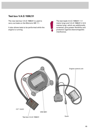
Test box V.A.G 1598/31
The new test box V.A.G 1598/31 is used to
carry out tests on the Motronic ME 7.1.
It also allows tests to be performed while the
engine is running.
VAS 5051VAS 5051
SSP 198/65
VAS 5051
Test box V.A.G 1598/31
Engine control unit
Earth
The test leads V.A.G 1598/31-1 (1
metre long) and V.A.G 1598/31-2 (2.5
metres long), which are additionally
screened, give greater flexibility and
protection against electromagnetic
interference.