Page 41 of 72

42
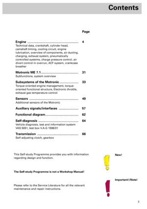
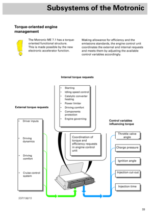
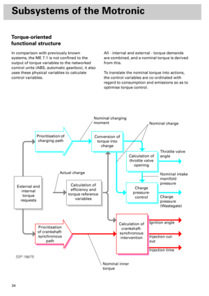
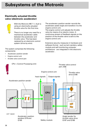
Subsystems of the Motronic
To enable the exact angular position of the throttle valve to be identified, angle senders for
throttle valve drive G187 and G188 must be learnt .
By moving the throttle valve into predefined positions, the values of the angle senders are stored
in the control unit (calibrated) and checked for plausibility. The state of the mechanics (terminals,
weak springs) in the throttle valve control part is determined by evaluating the throttle valve’s
reaction speed.
... involves not only learning the throttle
valve position, but also a complete check of
the throttle valve control part
... can be performed using the following
three methods:
•
manually
- provided the ignition has been
switched on for at least 24 minutes without
operating the starter or accelerator.
•
automatically -
provided the need for adaption
is acknowledged.
•
specifically -
by initiating basic setting 04 in
measured value block 60 (refer to Workshop
Manual)
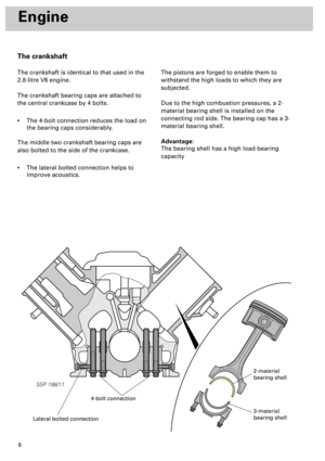
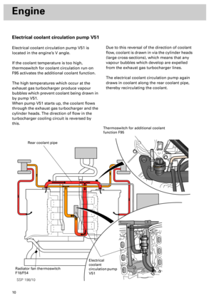
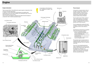
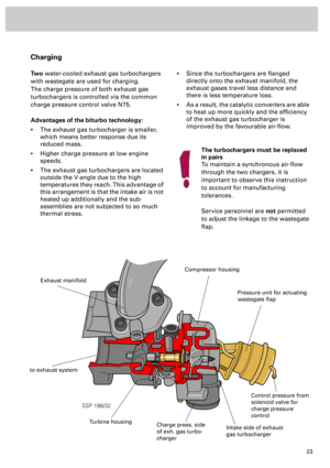
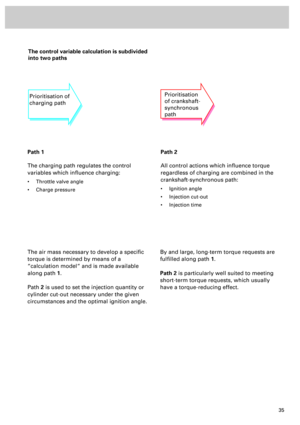
• The upper electrical limit stop
is defined in the control unit does not
need to be learned.
As in the
fully open position
, the
shaft diameter is greater than
the thickness of the throttle
butterfly.
SSP 198/23
Upper mechanical limit stop
Position at upper electrical limit stop
Basic adjustment (adaption) ...
Adaption conditions
For basic setting (adaption), the test
conditions described in the
Workshop Manual must be met.
The basic setting routine will be
cancelled if the test conditions are
not fulfilled
while
it is in progress.
Page 42 of 72

43
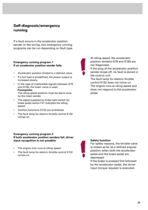
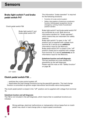
Emergency running program 1
If an angle sender for throttle valve drive fails
or an implausible signal is received:
• Torque-increasing requests on engine, e.g. CCS,
EBC (engine braking control) are suppressed.
• The fault lamp for electrical throttle control K132
comes on.
Prerequisite:
An intact angle sender and plausible
air mass flow. The air mass flow is
indicated by the air mass meter and
the charge pressure sender G31.
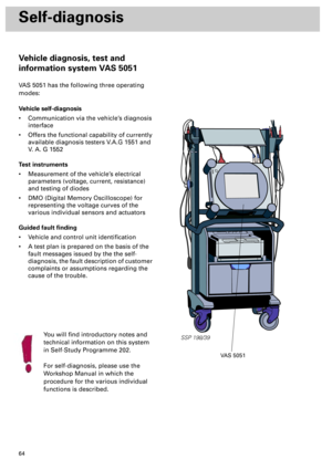
Self-diagnosis/emergency running mode
If a fault occurs in the throttle valve control part or in the wiring, three emergency running
programs can be run, depending on fault type.
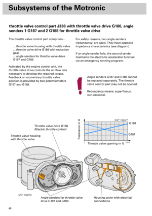
Emergency running program 2
If the throttle valve drive fails or malfunctions:
• The throttle valve drive is switched off and the
throttle valve goes into the emergency running
position. This results in considerable loss of
power, increased idling speed and possibly also
rough idling .
• Driver inputs are executed as far as possible via
the ignition angle and charge pressure. The
engine shows little response to the throttle.
• The fault lamp for electrical throttle control K132
comes on.
Prerequisite:
Emergency running program 2 is only
run if both angle senders for throttle
valve drive recognise the emergency
running position.
Emergency running program 3
If the throttle valve position is not clearly
recognisable and/or if the throttle valve is not
definitely known to be in the emergency
running position:
• The throttle valve drive is switched off and the
throttle valve goes into the emergency running
position. This results in considerable loss of
power, increased idling speed and possibly also
rough idling.
• The engine speed is limited to approx. 1200 rpm
by restricting the injection.
• The fault lamp for electric throttle control K132
comes on.
Repair work may not be performed on
the throttle valve control part J338! If
G186, G187 or G188 becomes faulty,
unit J338 must be replaced
completely and a
basic setting
performed.
Page 43 of 72
44
Subsystems of the Motronic
120
180
°C 60
90
12
93
6
120
°C 60
12
16
120
100
80
50
30
10140
1234
5
6
7
160
180
200
220
260
Volt8
1/2
1/1
8
0
EPC
EPC
SSP 198/47
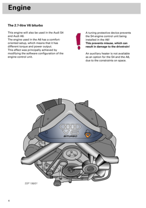
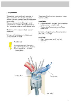
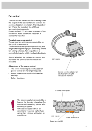
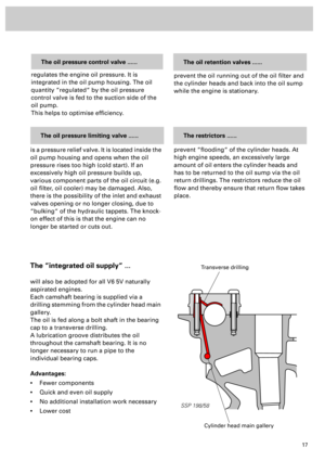
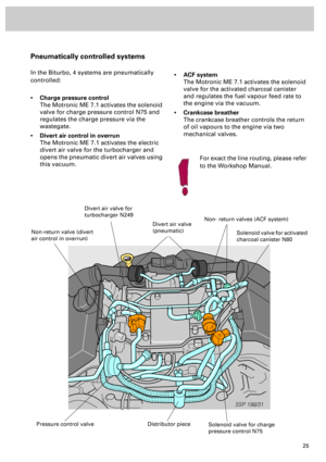
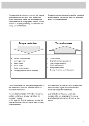
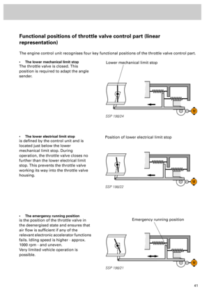
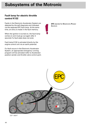
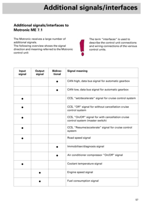
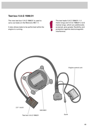
Fault lamp for electric throttle
control K132
Faults in the Electronic Accelerator System are
detected by the self-diagnosis and indicated
via the separate EPC fault lamp. At the same
time, an entry is made in the fault memory.
When the ignition is turned on, the fault lamp
comes on and must go out again after 3
seconds if a fault state does not exist.
Fault lamp K132 is activated directly by the
engine control unit via an earth potential.
If a fault occurs in the Electronic Accelerator
System, an appropriate emergency running
program will be activated (refer to Accelerator
position sender and throttle valve control part).
EPC
stands for
E
lectronic
P
ower
C
ontrol.
Page 44 of 72
45
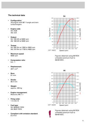
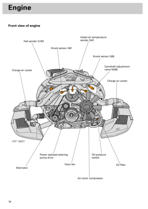
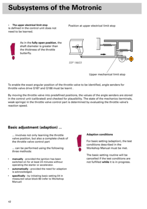
SSP 198/34
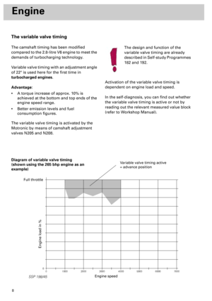
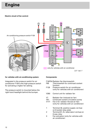
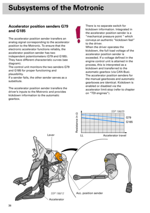
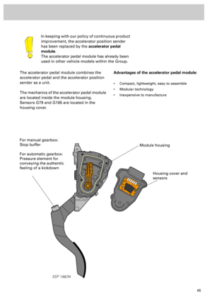
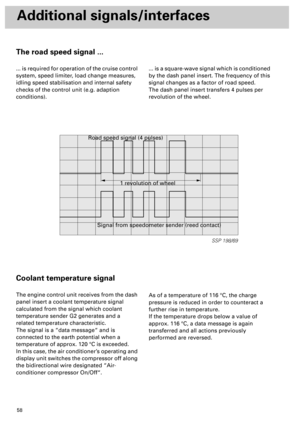
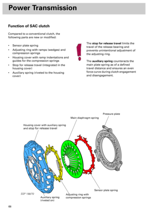
The accelerator pedal module combines the
accelerator pedal and the accelerator position
sender as a unit.
The mechanics of the accelerator pedal module
are located inside the module housing.
Sensors G79 and G185 are located in the
housing cover.In keeping with our policy of continuous product
improvement, the accelerator position sender
has been replaced by the
accelerator pedal
module
.
The accelerator pedal module has already been
used in other vehicle models within the Group.
Advantages of the accelerator pedal module:
• Compact, lightweight, easy to assemble
• Modular technology
• Inexpensive to manufacture
Module housing
Housing cover and
sensors
For manual gearbox:
Stop buffer
For automatic gearbox:
Pressure element for
conveying the authentic
feeling of a kickdown
Page 45 of 72

46
SSP 198/26
Subsystems of the Motronic
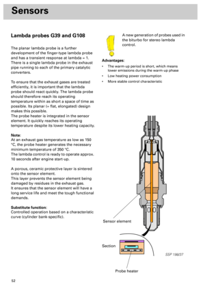
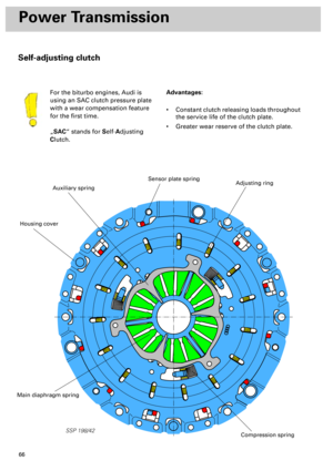
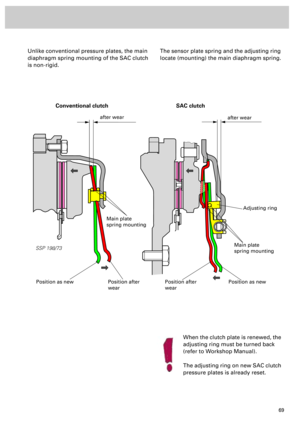
Exhaust gas temperature control
A new feature of Audi automobiles
is a function which monitors
exhaust gas temperature over the
entire engine speed range.
For turbocharged engines, the maximum
permissible exhaust gas temperature is a key
design criterion.
To protect the exhaust gas turbocharger and
the exhaust manifold, the exhaust gas
temperature should not exceed 1000 °C for a
lengthy period of time.
Since many of the components which
influence the exhaust gas temperature have
tolerances, thermodynamic adaptation
previously took place at 950 °C for safety’s
sake.
This was achieved by enriching the air/fuel
mixture.
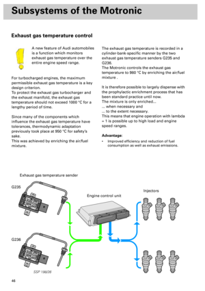
The exhaust gas temperature is recorded in a
cylinder-bank-specific manner by the two
exhaust gas temperature senders G235 and
G236.
The Motronic controls the exhaust gas
temperature to 980 °C by enriching the air/fuel
mixture .
It is therefore possible to largely dispense with
the prophylactic enrichment process that has
been standard practice until now.
The mixture is only enriched...
... when necessary and
... to the extent necessary.
This means that engine operation with lambda
= 1 is possible up to high load and engine
speed ranges.
Advantage:
• Improved efficiency and reduction of fuel
consumption as well as exhaust emissions.
Exhaust gas temperature sender
Engine control unit
Injectors
G235
G236
Page 46 of 72

47
SSP/198/13
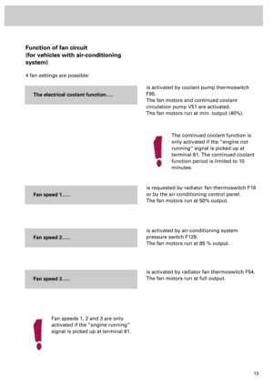
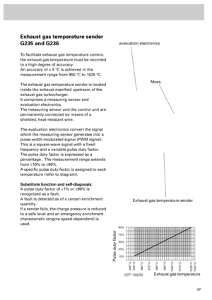
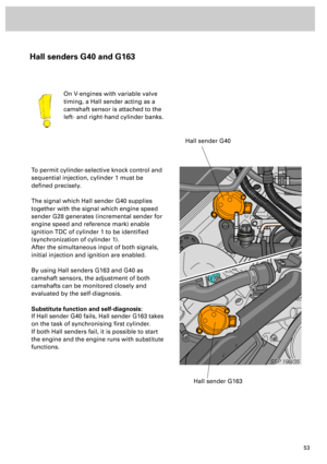
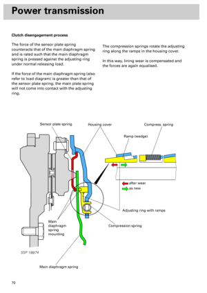
Exhaust gas temperature sender
G235 and G236
To facilitate exhaust gas temperature control,
the exhaust gas temperature must be recorded
to a high degree of accuracy.
An accuracy of ± 5 °C is achieved in the
measurement range from 950 °C to 1025 °C.
The exhaust gas temperature sender is located
inside the exhaust manifold upstream of the
exhaust gas turbocharger.
It comprises a measuring sensor and
evaluation electronics.
The measuring sensor and the control unit are
permanently connected by means of a
shielded, heat-resistant wire.
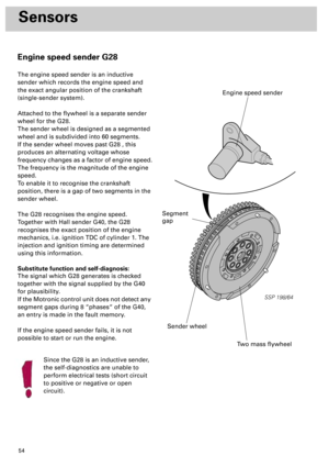
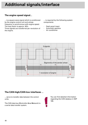
The evaluation electronics convert the signal
which the measuring sensor generates into a
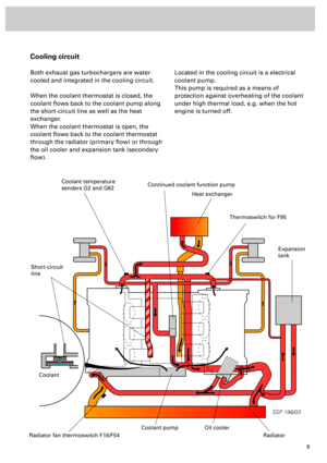
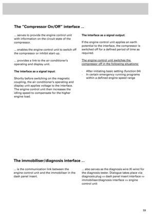
pulse-width-modulated signal (PWM signal).
This is a square-wave signal with a fixed
frequency and a variable pulse duty factor.
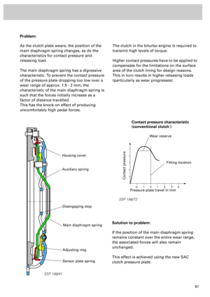
The pulse duty factor is expressed as a
percentage . The measurement range extends
from
³
10% to
£
90%.
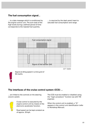
A specific pulse duty factor is assigned to each
temperature (refer to diagram).
Substitute function and self-diagnosis:
A pulse duty factor of <1% or >99% is
recognised as a fault.
A fault is detected as of a certain enrichment
quantity.
If a sender fails, the charge pressure is reduced
to a safe level and an emergency enrichment
characteristic (engine speed-dependent) is
used.
Exhaust gas temperature sender
evaluation electronics
SSP 198/56
90%
70%
50%
30%
10%
945°C
950°C
960°C
970°C
980°C
990°C
1000°C
1010°C
1025°C
1030°C
Exhaust gas temperature
Pulse duty factor
Meas.
Page 47 of 72
Page 48 of 72

49
Sensors
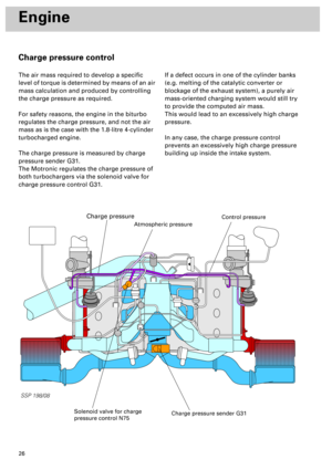
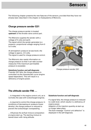
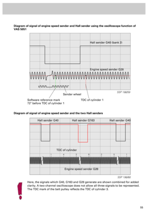
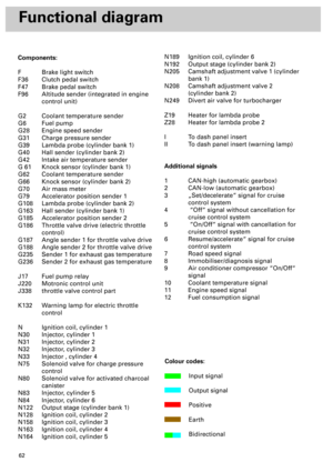
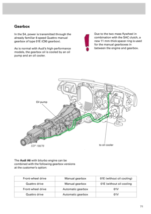
Charge pressure sender G31
The charge pressure sender is located
upstream of the throttle valve control part.
The Motronic supplies the sender with a
voltage of 5 volts and earth.
The signal which the sender generates is a
pressure- proportional voltage ranging from 0
to 5 volts.
At atmospheric pressure (at sea-level), the
voltage is approx. 2.5 volts.
The signal is used for charge pressure control.
The Motronic also needs information on
charge pressure so that it can take counter-
measures if the maximum permissible
pressure is exceeded.
Substitute function and self-diagnosis:
If sender G31 fails, the charge pressure is
controlled via the characteristic curve (engine
speed-dependent). This will result in a
deficiency of engine power.
SSP 198/29
Charge pressure sender G31
The altitude sender F96 ....
... is integrated in the engine control unit, as is
normally the case with turbocharged engines.
... is required to control the charge pressure. In
conditions of decreasing air pressure (lower
density), the charge pressure is reduced to
prevent the turbocharger overspeeding.
... influences the air/fuel mixture composition
at engine start-up. The starting mixture is
leaned down with rising altitude.Substitute function and self-diagnosis
If a signal fails, the charge pressure is reduced
to a safe level, which results in a deficiency of
engine power.
Adaption of the injection quantity at start-up
no longer takes place.
The fault message “Control unit defective“ is
displayed in the self-diagnosis.
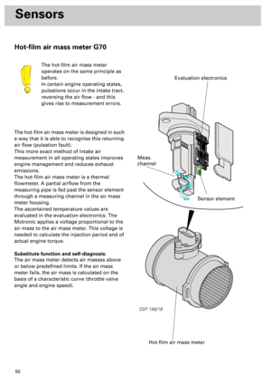
The following chapter presents the new features of the sensors, provided that they have not
already been described in the chapter on Subsystems of Motronic.