Page 49 of 72

50
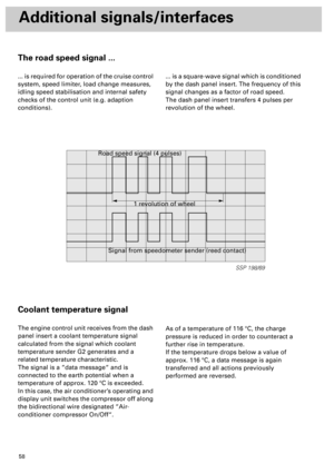
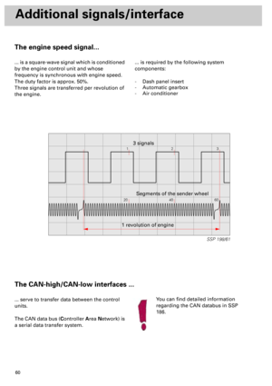
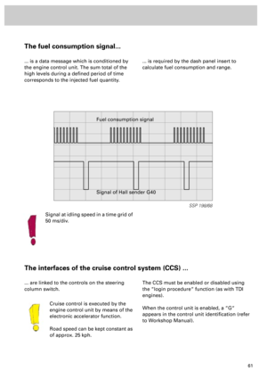
SSP 198/16
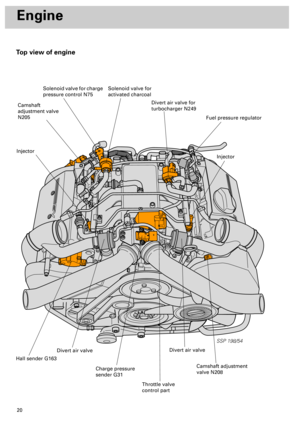
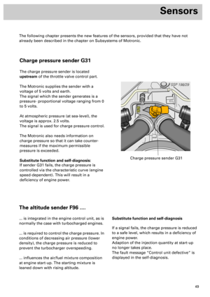
Sensors
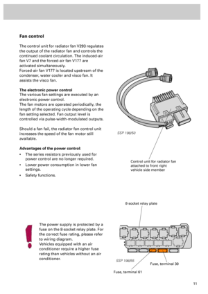
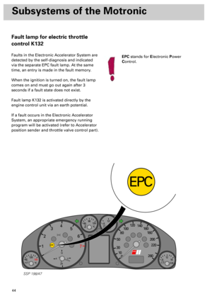
The hot-film air mass meter
operates on the same principle as
before.
In certain engine operating states,
pulsations occur in the intake tract,
reversing the air flow - and this
gives rise to measurement errors.
The hot-film air mass meter is designed in such
a way that it is able to recognise this returning
air flow (pulsation fault).
This more exact method of intake air
measurement in all operating states improves
engine management and reduces exhaust
emissions.
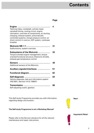
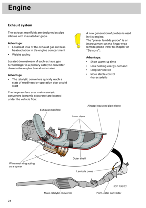
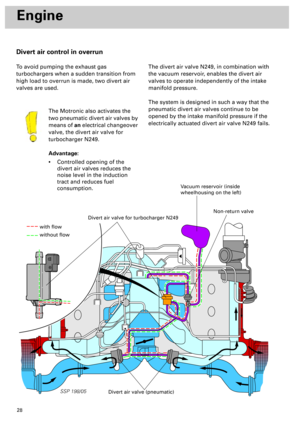
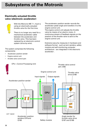
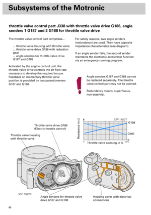
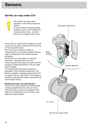
The hot-film air mass meter is a thermal
flowmeter. A partial airflow from the
measuring pipe is fed past the sensor element
through a measuring channel in the air mass
meter housing.
The ascertained temperature values are
evaluated in the evaluation electronics. The
Motronic applies a voltage proportional to the
air mass to the air mass meter. This voltage is
needed to calculate the injection period and of
actual engine torque.
Substitute function and self-diagnosis:
The air mass meter detects air masses above
or below predefined limits. If the air mass
meter fails, the air mass is calculated on the
basis of a characteristic curve (throttle valve
angle and engine speed).
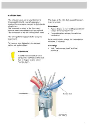
Hot-film air mass meter
Sensor element
Meas.
channel
Evaluation electronics
Hot-film air mass meter G70
Page 50 of 72

51
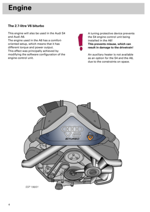
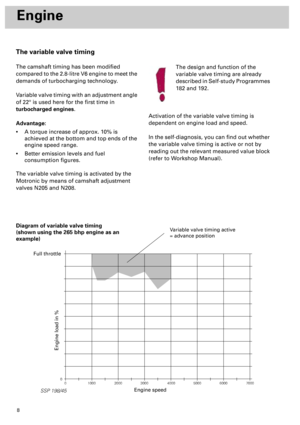
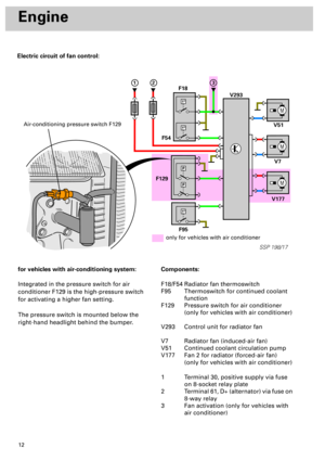
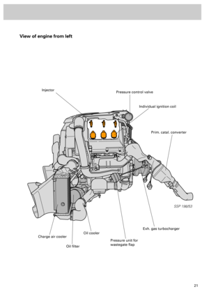
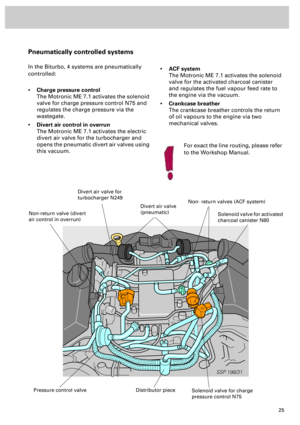
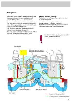
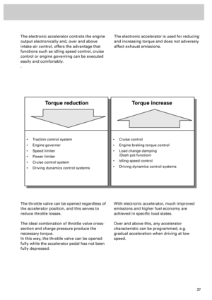
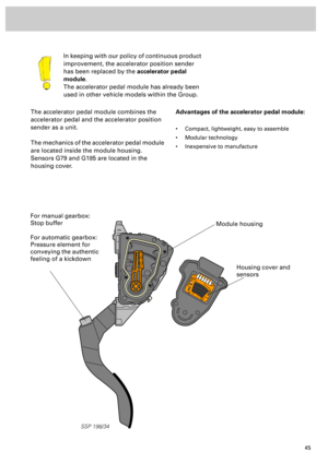
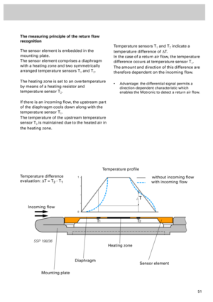
The measuring principle of the return flow
recognition
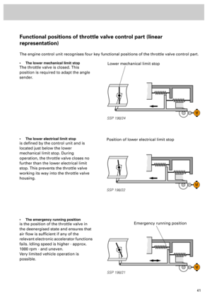
The sensor element is embedded in the
mounting plate.
The sensor element comprises a diaphragm
with a heating zone and two symmetrically
arranged temperature sensors T
1 and T2.
The heating zone is set to an overtemperature
by means of a heating resistor and
temperature sensor T
2.
If there is an incoming flow, the upstream part
of the diaphragm cools down along with the
temperature sensor T
1.
The temperature of the upstream temperature
sensor T
2 is maintained due to the heated air in
the heating zone.
Temperature sensors T1 and T2 indicate a
temperature difference of DT.
In the case of a return air flow, the temperature
difference occurs at temperature sensor T
1.
The amount and direction of this difference are
therefore dependent on the incoming flow.
• Advantage: the differential signal permits a
direction-dependent characteristic which
enables the Motronic to detect a return air flow.
T
T
1T2
1
0
SSP 198/36
Incoming flow
Temperature profile
without incoming flow
with incoming flow
Mounting plate
Diaphragm
Heating zone
Sensor element
Temperature difference
evaluation: DT = T
2 - T1
Page 51 of 72

52
Sensors
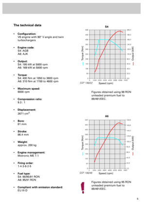
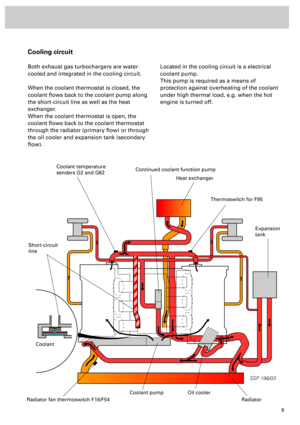
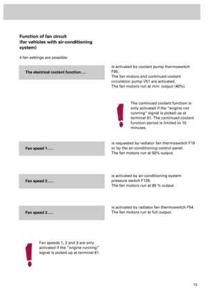
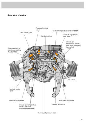
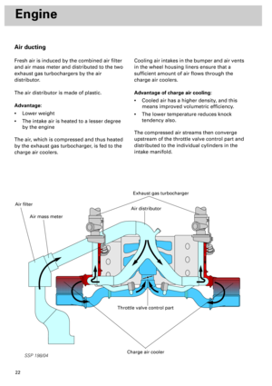
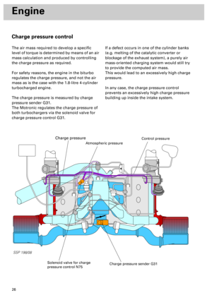
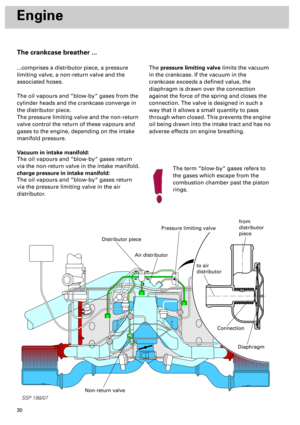
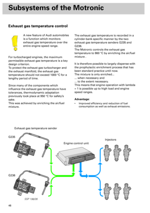
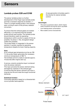
Lambda probes G39 and G108
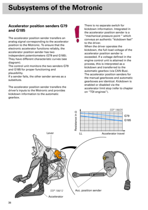
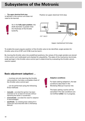
The planar lambda probe is a further
development of the finger-type lambda probe
and has a transient response at lambda = 1.
There is a single lambda probe in the exhaust
pipe running to each of the primary catalytic
converters.
To ensure that the exhaust gases are treated
efficiently, it is important that the lambda
probe should react quickly. The lambda probe
should therefore reach its operating
temperature within as short a space of time as
possible. Its planar (= flat, elongated) design
makes this possible.
The probe heater is integrated in the sensor
element. It quickly reaches its operating
temperature despite its lower heating capacity.
Note:
At an exhaust gas temperature as low as 150
°C, the probe heater generates the necessary
minimum temperature of 350 °C.
The lambda control is ready to operate approx.
10 seconds after engine start-up.
A porous, ceramic protective layer is sintered
onto the sensor element.
This layer prevents the sensor element being
damaged by residues in the exhaust gas.
It ensures that the sensor element will have a
long service life and meet the tough functional
demands.
Substitute function:
Controlled operation based on a characteristic
curve (cylinder bank-specific).A new generation of probes used in
the biturbo for stereo lambda
control.
Advantages:
• The warm-up period is short, which means
lower emissions during the warm-up phase
• Low heating power consumption
• More stable control characteristic
SSP 198/37
Section
Probe heater
Sensor element
Page 52 of 72

53
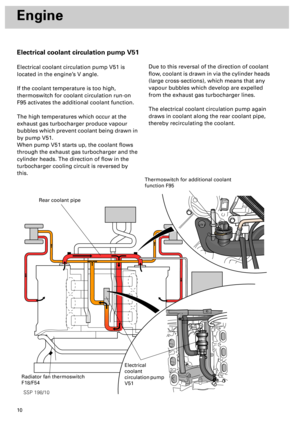
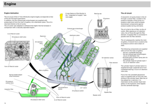
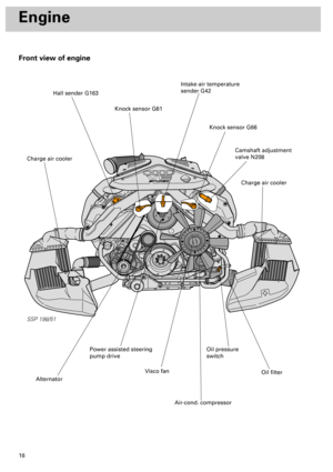
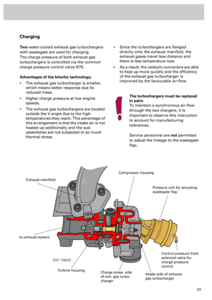
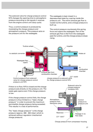
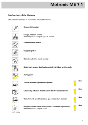
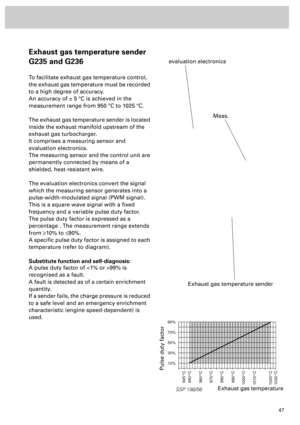
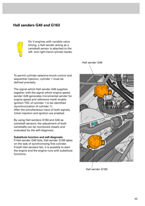
Hall senders G40 and G163
To permit cylinder-selective knock control and
sequential injection, cylinder 1 must be
defined precisely.
The signal which Hall sender G40 supplies
together with the signal which engine speed
sender G28 generates (incremental sender for
engine speed and reference mark) enable
ignition TDC of cylinder 1 to be identified
(synchronization of cylinder 1).
After the simultaneous input of both signals,
initial injection and ignition are enabled.
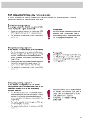
By using Hall senders G163 and G40 as
camshaft sensors, the adjustment of both
camshafts can be monitored closely and
evaluated by the self-diagnosis.
Substitute function and self-diagnosis:
If Hall sender G40 fails, Hall sender G163 takes
on the task of synchronising first cylinder.
If both Hall senders fail, it is possible to start
the engine and the engine runs with substitute
functions.On V-engines with variable valve
timing, a Hall sender acting as a
camshaft sensor is attached to the
left- and right-hand cylinder banks.
SSP 198/35
Hall sender G40
Hall sender G163
Page 53 of 72
.
Attached to")
54
Sensors
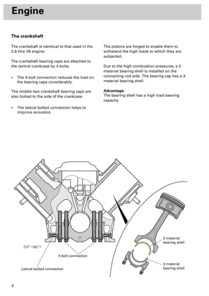
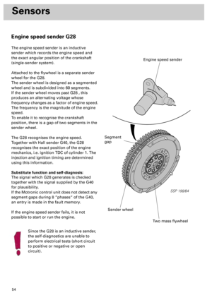
Engine speed sender G28
The engine speed sender is an inductive
sender which records the engine speed and
the exact angular position of the crankshaft
(single-sender system).
Attached to the flywheel is a separate sender
wheel for the G28.
The sender wheel is designed as a segmented
wheel and is subdivided into 60 segments.
If the sender wheel moves past G28 , this
produces an alternating voltage whose
frequency changes as a factor of engine speed.
The frequency is the magnitude of the engine
speed.
To enable it to recognise the crankshaft
position, there is a gap of two segments in the
sender wheel.
The G28 recognises the engine speed.
Together with Hall sender G40, the G28
recognises the exact position of the engine
mechanics, i.e. ignition TDC of cylinder 1. The
injection and ignition timing are determined
using this information.
Substitute function and self-diagnosis:
The signal which G28 generates is checked
together with the signal supplied by the G40
for plausibility.
If the Motronic control unit does not detect any
segment gaps during 8 “phases“ of the G40,
an entry is made in the fault memory.
If the engine speed sender fails, it is not
possible to start or run the engine.
Since the G28 is an inductive sender,
the self-diagnostics are unable to
perform electrical tests (short circuit
to positive or negative or open
circuit).
SSP 198/64
Two mass flywheel
Sender wheel
Engine speed sender
Segment
gap
Page 54 of 72
55
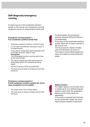
SSP 198/60
1436251
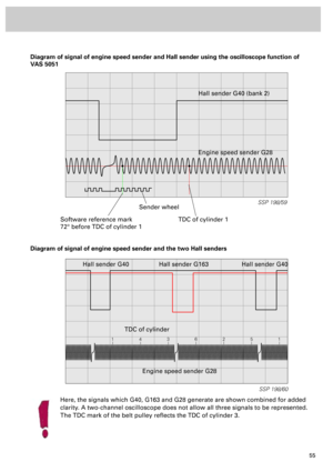
Diagram of signal of engine speed sender and Hall sender using the oscilloscope function of
VAS 5051
SSP 198/59
Software reference mark
72° before TDC of cylinder 1TDC of cylinder 1
Sender wheelHall sender G40 (bank 2)
Engine speed sender G28
Diagram of signal of engine speed sender and the two Hall senders
Hall sender G163 Hall sender G40
TDC of cylinder
Engine speed sender G28 Hall sender G40
Here, the signals which G40, G163 and G28 generate are shown combined for added
clarity. A two-channel oscilloscope does not allow all three signals to be represented.
The TDC mark of the belt pulley reflects the TDC of cylinder 3.
Page 55 of 72

56
Sensors
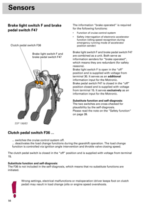
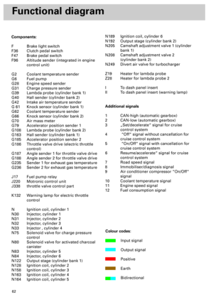
Brake light switch F and brake
pedal switch F47The information “brake operated“ is required
for the following functions:
• Function of cruise control system
• Safety interrogation of electronic accelerator
function (idling speed recognition during
emergency running mode of accelerator
position sender)
Brake light switch F and brake pedal switch F47
are combined as a unit. Both serve as
information senders for “brake operated“,
which means they are redundant (for safety
reasons).
Brake light switch F is open in the “off”
position and is supplied with voltage from
terminal 30. It serves as an additional
information input for the Motronic.
Brake pedal switch F47 is closed in the “off”
position closed and is supplied with voltage
from terminal 15. It serves exclusively as an
information input for the Motronic.
Substitute function and self-diagnosis:
The two switches are cross-checked for
plausibility by the self-diagnosis.
Please read the note on the “Safety function“
on page 39.
Clutch pedal switch F36 ...
Wrong settings, electrical malfunctions or maloperation (driver keeps foot on clutch
pedal) may result in load change jolts or engine speed overshoots.
... switches the cruise control system off.
... deactivates the load change functions during the gearshift operation. The load change
function is controlled via ignition angle intervention and throttle valve closing speed.
The clutch pedal switch is closed in the “off” position and is supplied with voltage from terminal
15.
Substitute function and self-diagnosis:
The F36 is not included in the self-diagnosis, which means that no substitute functions are
initiated.
SSP 198/63
Brake light switch F and
brake pedal switch F47
Clutch pedal switch F36
Page 56 of 72
57
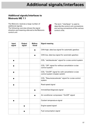
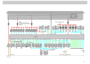
Additional signals/interfaces
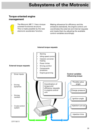
Additional signals/interfaces to
Motronic ME 7.1
The Motronic receives a large number of
additional signals.
The following overview shows the signal
direction and meaning referred to the Motronic
control unit
Input
signalOutput
signalBidirec-
tionalSignal meaning
·CAN-high, data bus signal for automatic gearbox
·CAN-low, data bus signal for automatic gearbox
·CCS, “set/decelerate“ signal for cruise control system
·CCS, “Off“ signal for without cancellation cruise
control system
·CCS, “On/Off“ signal for with cancellation cruise
control system (master switch)
·CCS, “Resume/accelerate“ signal for cruise control
system
·Road speed signal
·Immobiliser/diagnosis signal
·Air conditioner compressor “On/Off“ signal
·Coolant temperature signal
·Engine speed signal
·Fuel consumption signal
The term “interfaces“ is used to
describe the control unit connections
and wiring connections of the various
control units.