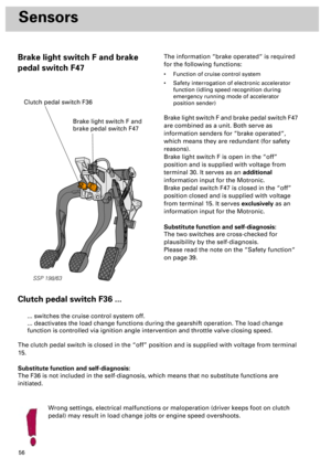
Page 17 of 72
18
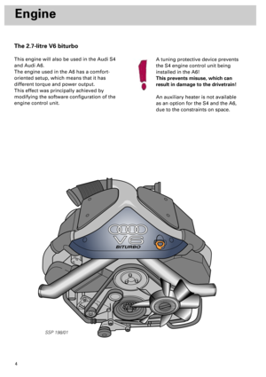
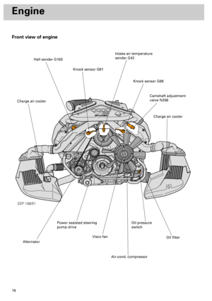
Front view of engine
SSP 198/51
Engine
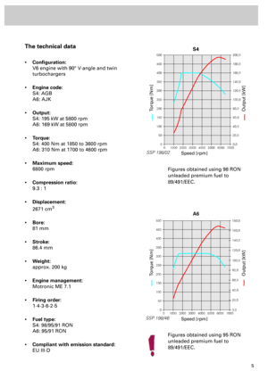
Camshaft adjustment
valve N208
Knock sensor G66
Intake-air temperature
sender G42
Knock sensor G61
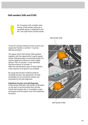
Hall sender G163
Charge air cooler
Charge air cooler
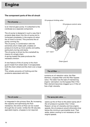
Oil filter
Oil pressure
switch
Air-cond. compressor
Visco fan
Alternator
Power assisted steering
pump drive
Page 18 of 72
19
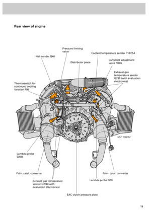
Rear view of engine
SSP 198/52
Hall sender G40
Thermoswitch for
continued cooling
function F95
Pressure limiting
valve
Distributor piece
Coolant temperature sender F18/F54
Camshaft adjustment
valve N205
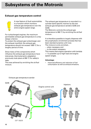
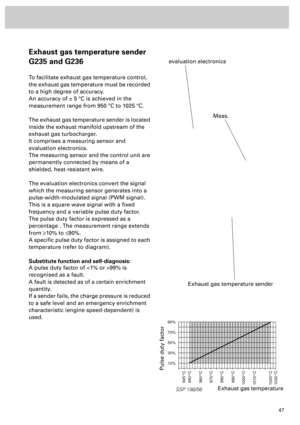
Exhaust gas
temperature sender
G235 (with evaluation
electronics)
Lambda probe
G108
Exhaust gas temperature
sender G236 (with
evaluation electronics)Lambda probe G39
SAC clutch pressure plate
Prim. catal. converterPrim. catal. converter
Page 19 of 72
20
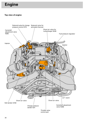
Engine
Top view of engine
SSP 198/54
Divert air valve for
turbocharger N249
Injector
Fuel pressure regulator
Solenoid valve for
activated charcoal Solenoid valve for charge
pressure control N75
Camshaft
adjustment valve
N205
Injector
Hall sender G163
Divert air valve
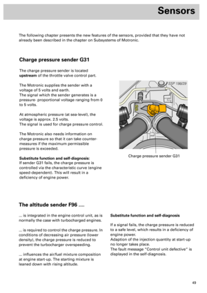
Charge pressure
sender G31
Throttle valve
control part
Camshaft adjustment
valve N208
Divert air valve
Page 20 of 72
21
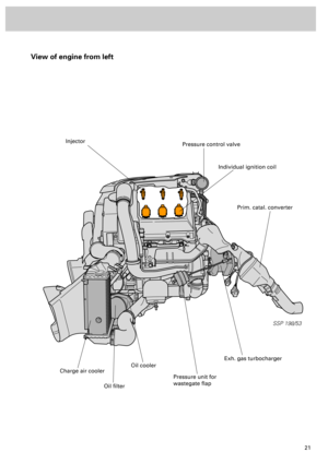
View of engine from left
SSP 198/53
Injector
Individual ignition coil
Pressure control valve
Prim. catal. converter
Exh. gas turbocharger
Pressure unit for
wastegate flap
Oil cooler
Oil filter
Charge air cooler
Page 21 of 72

22
SSP 198/04
Engine
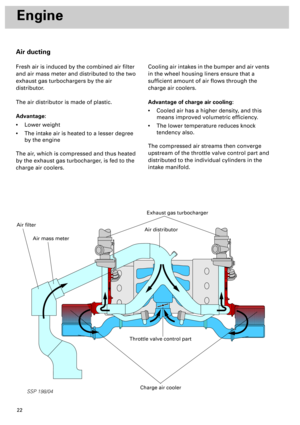
Air ducting
Fresh air is induced by the combined air filter
and air mass meter and distributed to the two
exhaust gas turbochargers by the air
distributor.
The air distributor is made of plastic.
Advantage:
•
Lower weight
•
The intake air is heated to a lesser degree
by the engine
The air, which is compressed and thus heated
by the exhaust gas turbocharger, is fed to the
charge air coolers.Cooling air intakes in the bumper and air vents
in the wheel housing liners ensure that a
sufficient amount of air flows through the
charge air coolers.
Advantage of charge air cooling:
•
Cooled air has a higher density, and this
means improved volumetric efficiency.
•
The lower temperature reduces knock
tendency also.
The compressed air streams then converge
upstream of the throttle valve control part and
distributed to the individual cylinders in the
intake manifold.
Exhaust gas turbocharger
Throttle valve control part
Charge air cooler
Air distributor
Air mass meter
Air filter
Page 22 of 72

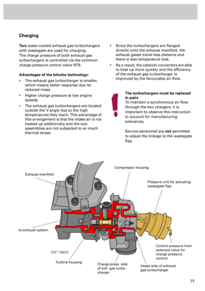
23
SSP 198/32
Charging
Two
water-cooled exhaust gas turbochargers
with wastegate are used for charging.
The charge pressure of both exhaust gas
turbochargers is controlled via the common
charge pressure control valve N75.
Advantages of the biturbo technology:
•
The exhaust gas turbocharger is smaller,
which means better response due its
reduced mass.
•
Higher charge pressure at low engine
speeds.
•
The exhaust gas turbochargers are located
outside the V-angle due to the high
temperatures they reach. This advantage of
this arrangement is that the intake air is not
heated up additionally and the sub-
assemblies are not subjected to so much
thermal stress.
•
Since the turbochargers are flanged
directly onto the exhaust manifold, the
exhaust gases travel less distance and
there is less temperature loss.
•
As a result, the catalytic converters are able
to heat up more quickly and the efficiency
of the exhaust gas turbocharger is
improved by the favourable air-flow.
Intake side of exhaust
gas turbocharger
Charge press. side
of exh. gas turbo-
charger
Exhaust manifold
to exhaust system
Pressure unit for actuating
wastegate flap
Control pressure from
solenoid valve for
charge pressure
control
The turbochargers must be replaced
in pairs
To maintain a synchronous air-flow
through the two chargers, it is
important to observe this instruction
to account for manufacturing
tolerances.
Service personnel are
not
permitted
to adjust the linkage to the wastegate
flap.
Turbine housing
Compressor housing
Page 23 of 72
.")
24
SSP 198/33
Engine
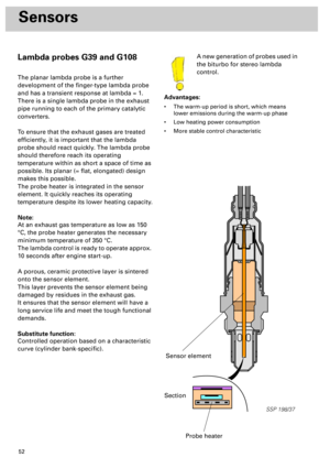
A new generation of probes is used
in this engine.
The “planar lambda probe“ is an
improvement on the finger-type
lambda probe (refer to chapter on
“Sensors”).
Advantage:
•
Short warm-up time
•
Less heating energy demand
•
Long service life
•
More stable control
characteristic
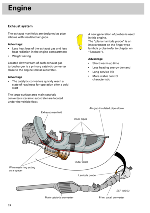
Exhaust system
The exhaust manifolds are designed as pipe
elbows with insulated air gaps.
Advantage:
•
Less heat loss of the exhaust gas and less
heat radiation in the engine compartment
•
Weight saving
Located downstream of each exhaust gas
turbocharger is a primary catalytic converter
close to the engine (metal substrate) .
Advantage
•
The catalytic converters quickly reach a
state of readiness for operation after a cold
start
The large-surface area main catalytic
converters (ceramic substrate) are located
under the vehicle floor.
Lambda probe
Prim. catal. converterMain catalytic converter
Exhaust manifold
Wire mesh ring acting
as a spacer
Air-gap-insulated pipe elbow
Outer shell
Inner pipes
Page 24 of 72

25
SSP 198/31
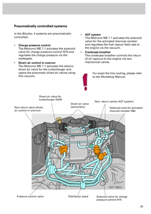
Pneumatically controlled systems
In the Biturbo, 4 systems are pneumatically
controlled:
•
Charge pressure control
The Motronic ME 7.1 activates the solenoid
valve for charge pressure control N75 and
regulates the charge pressure via the
wastegate.
•
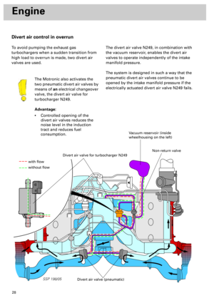
Divert air control in overrun
The Motronic ME 7.1 activates the electric
divert air valve for the turbocharger and
opens the pneumatic divert air valves using
this vacuum.
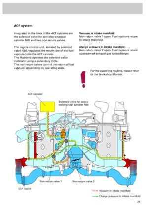
•
ACF system
The Motronic ME 7.1 activates the solenoid
valve for the activated charcoal canister
and regulates the fuel vapour feed rate to
the engine via the vacuum.
•
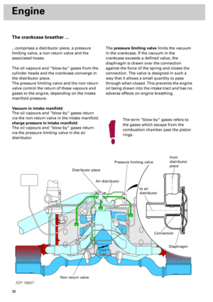
Crankcase breather
The crankcase breather controls the return
of oil vapours to the engine via two
mechanical valves.
Solenoid valve for charge
pressure control N75
Solenoid valve for activated
charcoal canister N80
Divert air valve for
turbocharger N249
Non- return valves (ACF system)
Distributor piecePressure control valve
Non-return valve (divert
air control in overrun)
Divert air valve
(pneumatic)
For exact the line routing, please refer
to the Workshop Manual.