Page 1153 of 1680

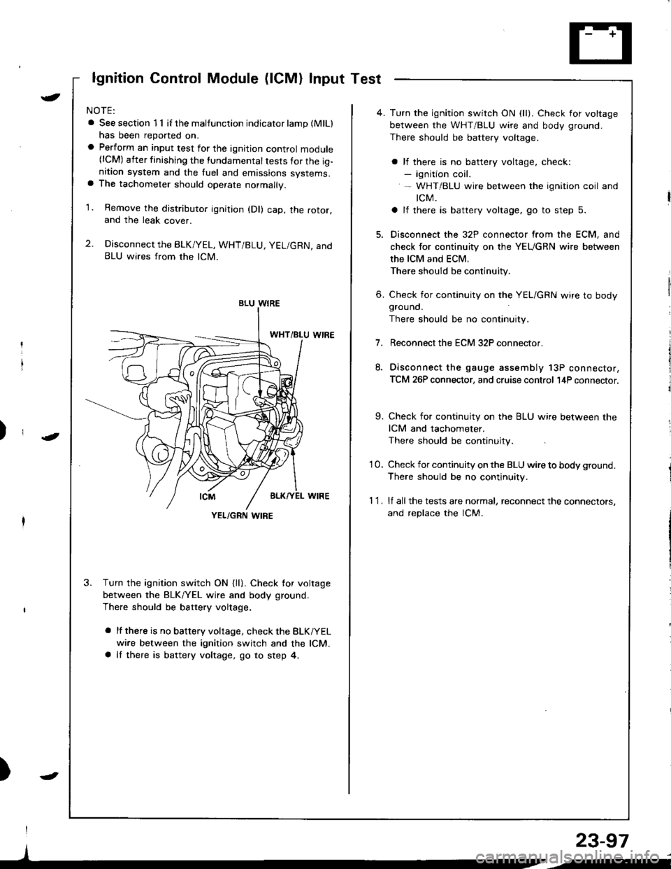
lgnition Control Module (lCM) Input Test
NOTE:
a See section 1 1 if the malfunction indicator lamp (MlLl
has been reported on.a Perform an input test for the ignition control module(lCM) after finishing the fundamental tests for the ig-nition system and the fuel and emissions systems.a The tachometer should operate normally.
1. Remove the distributo. ignition (Dl) cap, the rotor,and the leak cover.
2. Disconnect the BLK/YEL, WHT/BLU, YEL/GRN, andBLU wires from the lCM.
3. Turn the ignition switch ON {ll}. Check for voltage
between the BLK/YEL wire and body ground.
There should be battery voltage.
a lf there is no battery voltage, check the BLKiYEL
wire between the ignition switch and the lCM.a It there is battery voltage, go to step 4,
)
I
)
BLU WIRE
YEL/GRN I,\'IRE
4. Turn the ignition switch ON (ll). Check for voltage
between the WHT/BLU wire and body ground.
There should be battery voltage.
a lf there is no battery voltage, check:- ignition coil.- WHT/BLU wire between the ignition coil and
tcM.
a lf there is battery voltage, go to step 5.
5. Disconnect the 32P connector from the ECM, and
check for continuity on the YEUGRN wire between
the ICM and ECM.
There should be continuity.
6. Check for continuity on the YEL/GRN wire to bodygrouno.
There should be no continuity.
7.Reconnect the ECM 32P connector.
Disconnect the gauge assembly 13P connector,
TCM 26P connector, and cruise control l4P connector.
9. Check for continuity on the BLU wire between the
ICM and tachometer.
There should be continuity.
'10. Check for continuity on the BLU wire to body ground.
There should be no continuity.
1 1 . lf all the tests are normal, reconnect the connectors,
and replace the lCM.
23-97
/i
Page 1179 of 1680
UNDER.DASHFUSE/RELAY 8OX
No.l5 (7.54)
No 2s (7 5A)
Gircuit Diagram
WHTiGRN
| $il,�4,
V
MODULE(ICM)
ru{no unrno I(To pase 23 12s)
|BtU
No.rs (10A)FUSE
V
I
GAUGE ASSEMBLY
YEUBLU
t,,
| ,,J,,
1l
|;;il'-II SPEED II SENSoBIVSS) |-t-
. MAINTENANCEREMINDER UNIT' TCM' ECM' CRUISECONTROT UNlT
f7
I-oRN
BLKMHT
I
G501
I'YEUGRN YE
ln
tl
P**,,,'
ffirxl-"
louRED/BLU
.J'-
CRUISECONTROLUNIT
BLK
I
G10l
23-123
-/
UNDEF HOOD FUSE/RELAY BOX
Page 1234 of 1680
Dash Lights Brightness Control
Circuit Diagram
UNDER-HOOO FUSgRELAY 8OXUNDEN.DASHFUSE/RELAYEOXtX"f -.------^-;^*;;ilLrcrTswrc.
ffiwHT-lf-FEDGaN
, &TGEAN POSITION INOICATOROIMMING CIFCUIT.ATTGEAB POSITION CONSOLE LIGHT
. CRUISE COI,{TROL DIMMING CIRCUIT.CRUISE CONTHOT MAIN SWITCH LIGHT.GAUGE LIGHTS.HAZAFDWABN NG SWITCH LIGHT. HEATER CONTROL PANEL LIGHTS. REAR WINDOW DEFOGGER SWITCH LIGHT
23-178
Page 1246 of 1680
Brake
Brake
Lights
Switch TestHigh Mount Brake Light Replacement
\
t
2.
t.
3.
lf the brake lights do not go on. check the No. 52
{20 A) fuse in the under-hood fuse/relay box, and
the brake light bulbs in the taillight assembly and
high mount brake light.
lf the fuse and bulbs are OK, disconnect the 2P or
4P connector from the brake switch.
Without c.uisecontrol syst€mWilh cruisecontrol sYstem
Check for continuity between the B and C terminals.
There should be continuity with the brake pedal
pusneo.
a lf there is no continuity, replace the switch or ad-just pedal height (see section '19).
o It there is continuity, but the brake lights do not
go on, inspect for:
Poor ground (G5O3)
An open in the wire
AB
FS-A
lt--Ltl, t!,Z-\CD
-/Branl-ltl
tLatl\c
(LED typel
1. Remove the tour screws and the high mount brake
light, then disconnect the connectors.
TAILGATE SPOILER
HIGH MOUNT BRAKE LIGHT {tED TYPE}
23-190
Page 1264 of 1680
UNOEF.HOODFUSARELAYBOX
CRUISE CONTROISET/RESUME SWTCH($/-ih c.ute conrol)
23-208
Page 1307 of 1680
Cruise Control
)
Component LocationIndex
CRUISE LIGHT{Built into gauge assembly)Bulb Locations, page 23 122MAIN SWITCHTest, page 23-261Replacement, page 23-261SET/RESUME SWITCHTest, page 23 259Feplacement, page 23'259
BRAKE SwlTCHTest, page 23-262
CLUICH SWITCH IM/T)Test, page 23 262
cRutsEA/T GEAR POSITIONswtTcHTest, page 23-144,263Input Test, page 23 257
(cont'd)
23-253
Page 1308 of 1680
Cruise Control
Component Location Index (cont'd)
ACTUATOR ASSEMBLYTest, page 23-264Cable adjustment, page 23-264
23-254
Page 1310 of 1680

t
t;
i'l
I
dil
Gruise Gontrol
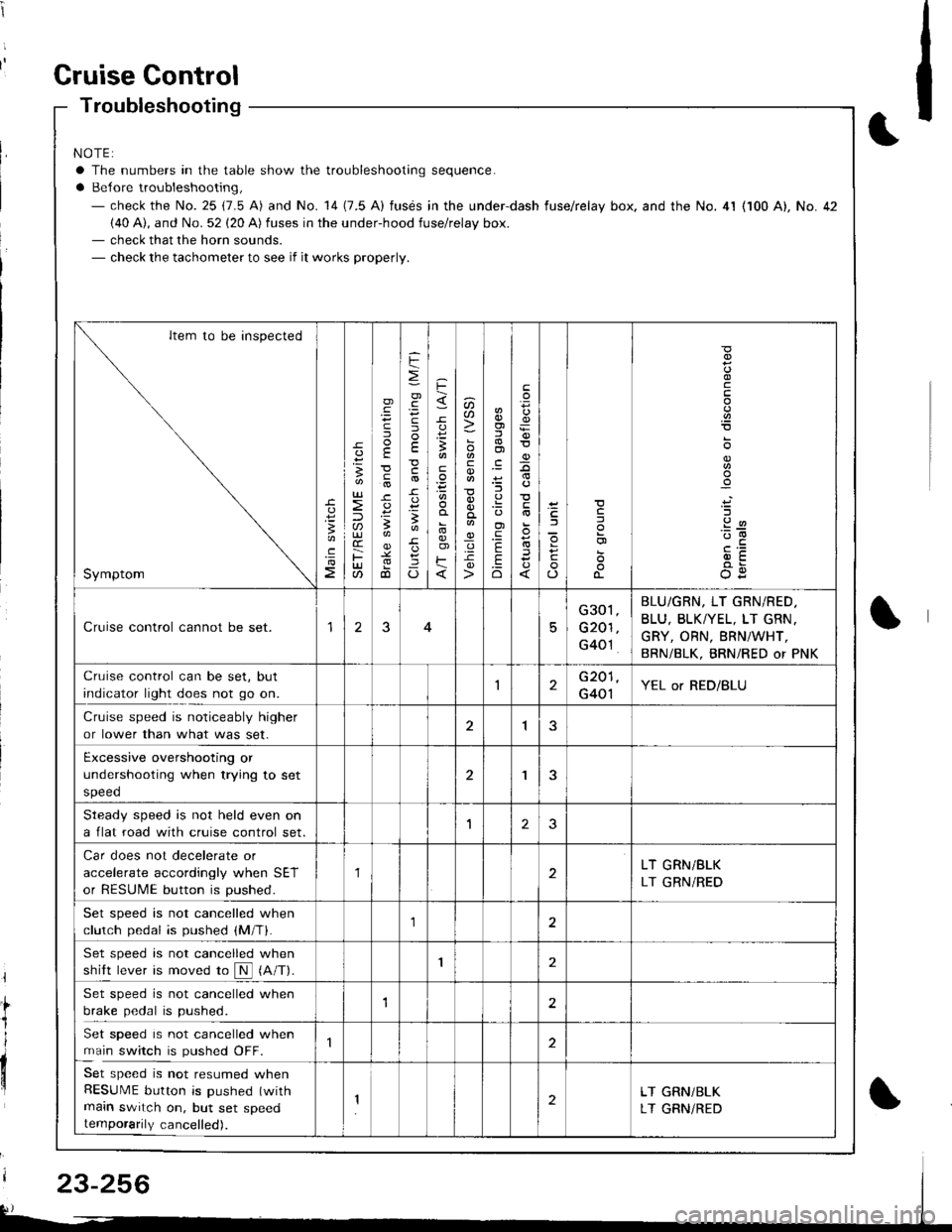
Troubleshooting
NOTE:
a The numbers in the table show the troubleshooting sequence.
a Belore troubleshooting,- check the No. 25 (7.5 A) and No. 14 (7.5 A) fusds in the under-dash fuse/relay box. and the No. 4l (100 A), No. 42(40 A), and No. 52 (20 A) fuses in the under-hood fuse/relay box.- check that the horn sounds.- check the tachometer to see if it works properly.
Item to be inspected
Symptom
c
:3
UJ
lU)(r
F(t
)
E
c
.
F
=
.g
E
-c
!-
Io
F
3
E
o)F
u)U'
co
_q.9-c
o)f,
ol
;l
E
.Eo
F
E
_9
)a
o
o-
o
c
.2
'::-c
OE
Cruise control cannot be set.15
G301
G201
G40't
BLU/GRN, LT GRN/RED.
BLU, BLKTYEL, LT GRN.
GRY, ORN, BRNiWHT,
BRN/BLK, BRNi RED or PNK
Cruise control can be set, but
indicator light does not go on.1G201
G401YEL or RED/BLU
Cruise speed is noticeably higher
or lower than what was set.1
Excessive overshooting or
undershooting when trying to set
speed
'I
Steadv soeed is not held even on
a flat road with cruise control set.1J
Car does not decelerate or
accelerate accordingly when SET
or RESUME button is pushed.
1LT GRN/BLK
LT GRN/RED
Set speed is not cancelled when
clutch pedal is pushed (M/T).1
Set speed is not cancelled when
shift lever is moved ro N (A/T).I
Set speed is not cancelled when
brake pedal is pushed.12
Set speed is not cancelled when
main switch is pushed OFF.
Set speed is not resumed whenRESUME button is pushed (with
main switch on, but set speedtemporarily cancelled).
2LT GRN/BLK
LT GRNiRED
23-256