1998 ACURA INTEGRA valve
[x] Cancel search: valvePage 1011 of 1680
Heater Control Panel
Replacement
J
2.
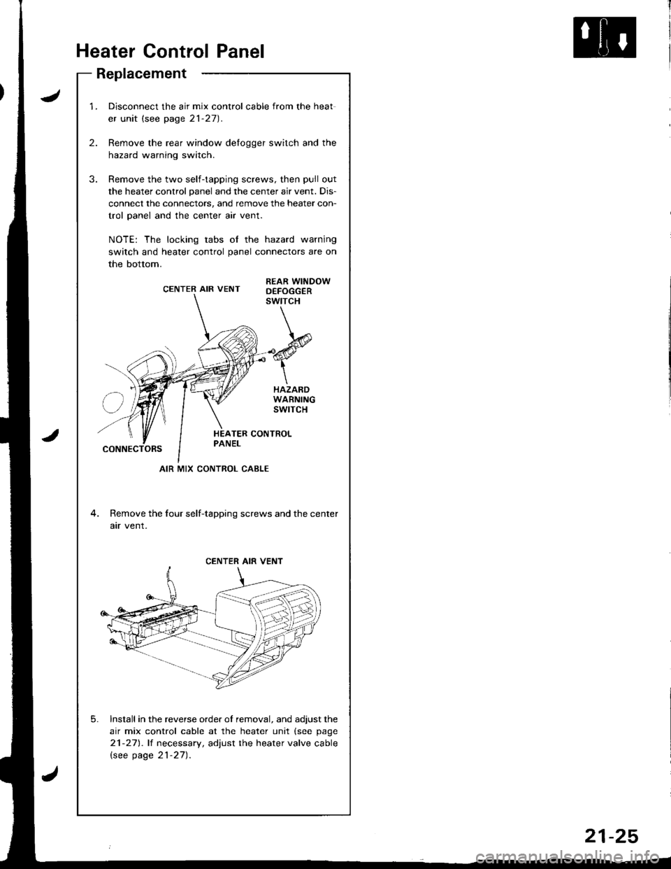
1.Disconnect the air mix control cable from the heat
er unit (see page 21-27).
Remove the rear window delogger switch and the
hazard warning switch.
Remove the two self-tapping screws, then pull out
the heater control panel and the center air vent. Dis-
connect the connectors, and remove the heater con-
trol panel and the center air vent.
NOTE: The locking tabs of the hazard warning
switch and heater control panel connectors are on
the bottom.
CENTER AIR VENTREAR WINDOWD€FOGGERswtrcH
HAZARDWARNINGswrTcH
CONNECTORS
4. Remove the four self-tapping screws and the center
atr vent.
Install in the reverse order of removal, and adjust the
air mix control cable at the heater unit (see page
21-271.lt necessary, adjust the heater valve cable
lsee page 21-27).
5.
AIR MIX CONTROL CABLE
CENTER AIR VENT
21-25
Page 1013 of 1680
Heater Valve Cable
Adjustment
Air Mix Control Cable
Adjustment
lnri
I
I
I
I
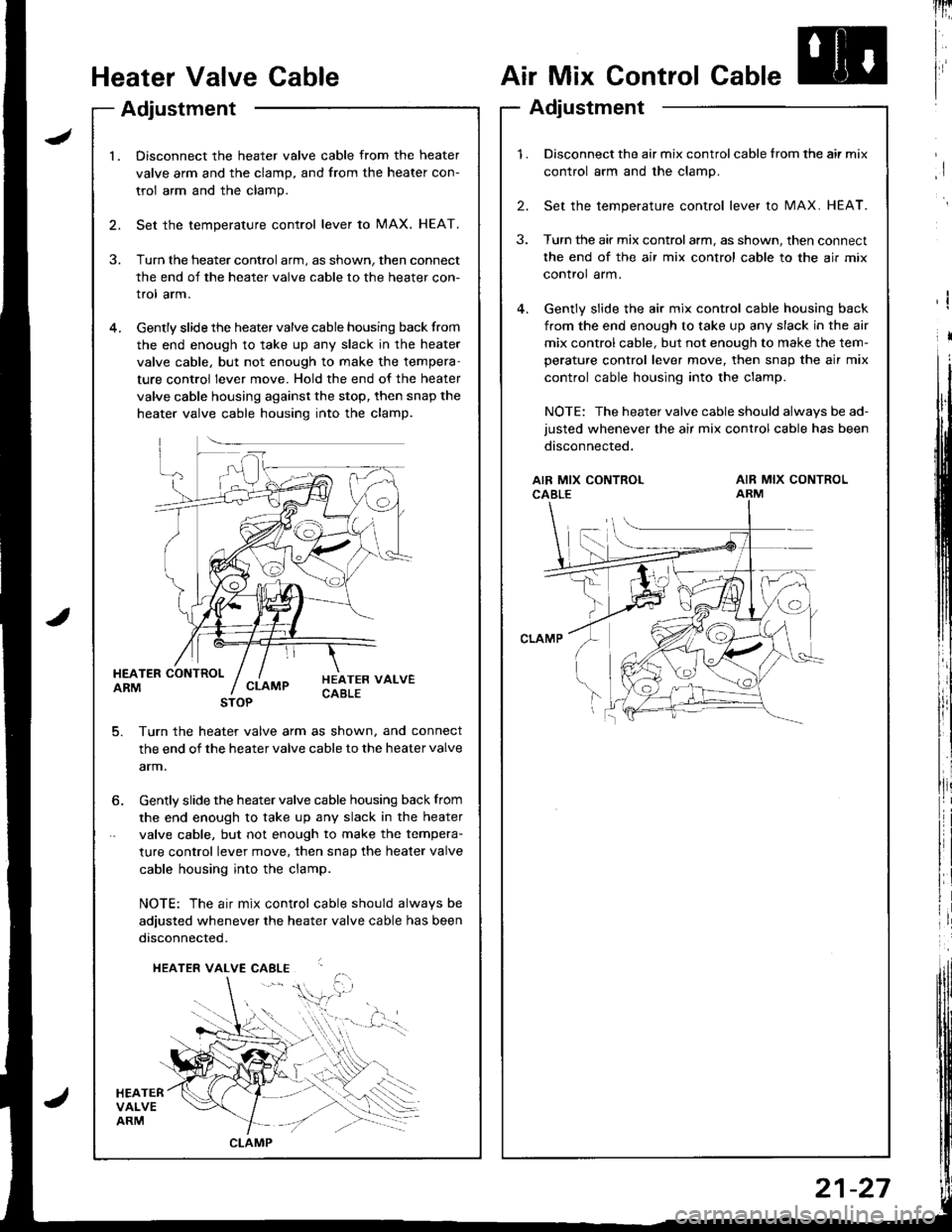
l.Disconnect the heater valve cable from the heater
valve arm and the clamp, and from the heater con-
trol arm and the clamp.
Set the temperature control lever to MAX. HEAT.
Turn the heater control arm, as shown, then connect
the end of the heater valve cable to the heater con-
trol arm.
Gently slide the heater valve cable housing back from
the end enough to take up any slack in the heater
valve cable, but not enough to make the tempera-
ture control lever move. Hold the end of the heater
valve cable housing against the stop, then snap the
heater valve cable housing into the clamp.
HEATER CONTROLARM
HEATERVALVEARM
HEATER VALVECABLECLAMP
5. Turn th€ heater valve arm as shown, and connect
the end of the heater valve cable to the heater valve
arm.
STOP
6. Gently slide the heater valve cable housing back from
the end enough to take up any slack in the heater
valve cable, but not enough to make the tempera-
ture control lever move. then snap the heater valve
cable housing into the clamp.
NOTE: The air mix control cable should alwavs be
adjusted whenever the heater valve cable has been
disconnected.
HEATER VALVE CABLE
,i$.
CLAMP
1.Disconnect the air mix control cable from the air mix
control arm and the clamp.
Set the temperature control lever to MAX. HEAT.
Turn the air mix controlarm, as shown, then connect
the end of the air mix control cable to the air mix
control arm.
Gently slide the air mix control cable housing back
from the end enough to take up any slack in the air
mix control cable, but not enough to make the tem-
perature control lever move, then snap the air mix
control cable housing into the clamp.
NOTE: The heater valve cable should always be ad-
justed whenever the air mix control cable has been
disconnected.
2.
3.
AIR MIX CONTROLCABLEAIR MIX CONTROLARM
21-27
Page 1020 of 1680
lllustrated Index
JSRS components are located in this area. Review the SRS component locations, precautions, and procedures in the SRS
section (23) before performing repairs or service.
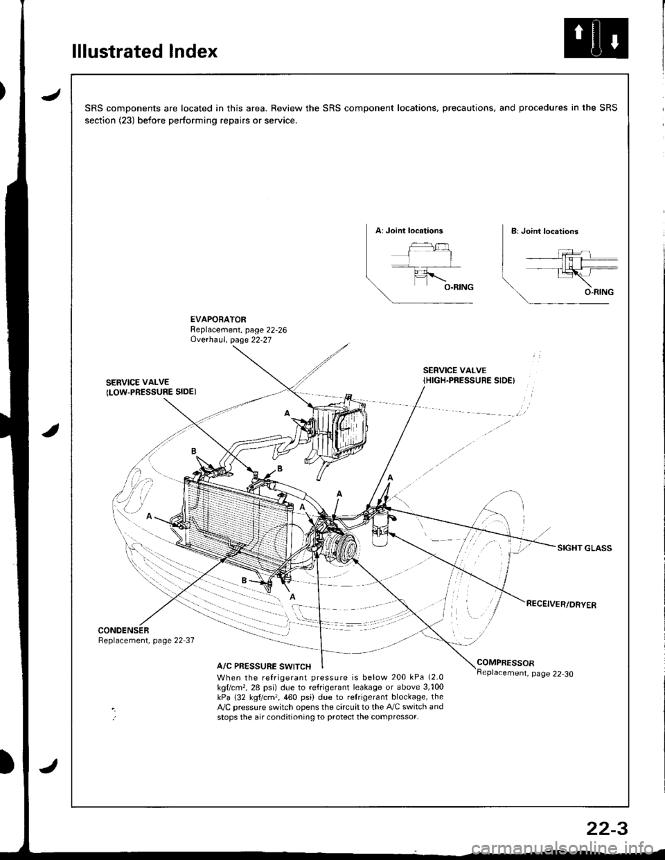
EVAPORATORReplacement, page 22,26Ove.haul. page 22-27
SERVICE VAI-VE
ILOW.PRESSURE SIDE)
SERVICE VALVE{HIGH.PRESSUEE SIDE}
SIGHT GLASS
CONOENSERReplacement, page 22 37
A/C PRESSURE SWITCHCOMPRESSOR
When the refrigerant pressure is below 200 kPa (2.0
kgllcm,, 28 psi) due to refrigerant leakage or above 3,'100kPa (32 kgtcm,,460 psi) due to relrigerant blockage, theA,/C pressure sw;tch opens the circuit to the A,/C switch andstops the air conditioning to protect the compressor.
page 22-30
22-3
Page 1023 of 1680
Description
Outline
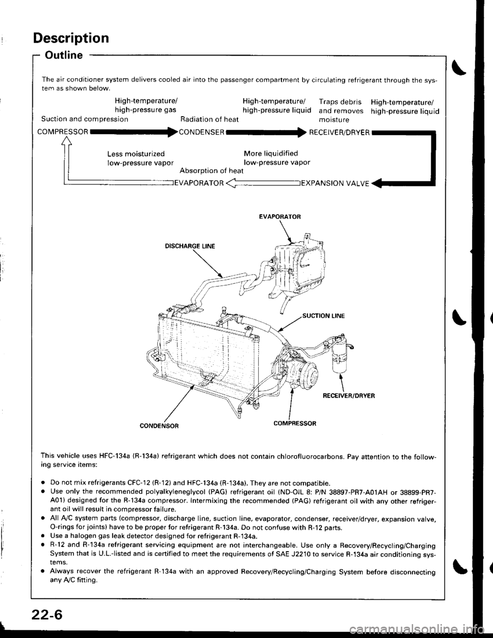
The air conditioner system delivers cooled air into the passenger companment by circulating retrigerant through the sys-
tem as shown below.
High-temperature/ H ig h-tem peratu rel Traps debris High-temperature/high-pressure gas high-pressure liquid and removes high-pressure liquidSuction and compression Radiation of heat moisture
covpnEsson -tl4con oetsen -rr{ REcEIvER/DRvER
More liqu idified
low-pressure vapor
Absorption of heat
Less moisturized
low-pressure vapor
EVAPORATOR -TEXPANS|ON VALVE
EVAPORATOR
CONDENSOR
This vehicle uses HFC-134a (R-134a) refrigerant which does not contain chlorofluorocarbons. Pay attention to the follow-ing service items:
. Do not mix refrigerants CFC-12 (R-12) and HFC-134a (R-134a). They are not compatible.. Use only the recommended polyalkyleneglycol (PAG) refrigerant oil (ND-OIL 8: P/N 38897-PR7-A01AH or 38899-PR7-A01) designed for the R-134a compressor. Intermixing the recommended (PAG) refrigerant oil with any other refriger-ant oil will result in compressor failure.
. All AVC system parts (compressor, discharge line, suction line. evaporator, condenser, receiver/dryer, expansion valve.O-rings for joints) have to be proper for refrigerant R-134a. Do not confuse with R-12 parts.
. Use a halogen gas leak detector designed for refrigerant R-134a.. R-12 and R-134a refrigerant servicing equipment are not interchangeable. Use only a Recovery/Recycling/ChargingSystem that is U.L.-listed and is certified to meet the requirements of SAE J2210 to service R-134a air conditioning sys-tems.
. Always recover the refrigerant R-134a with an approved Recovery/Recycling/Charging System before disconnectingany Ay'C fitting.
22-6
Page 1040 of 1680
J
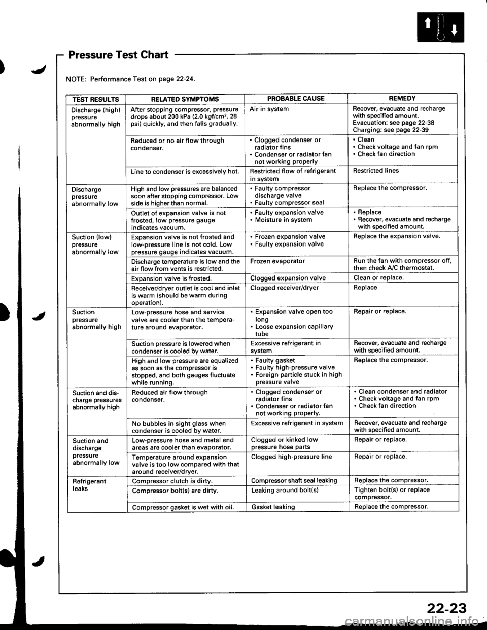
Pressure Test Chart
Performance Test on page 22.24.
TEST RESULTSRELATED SYMPTOMSPROBABLE CAUSEREMEDY
Discharge (highlpressure
abnormally high
After stopping compressor, pressure
drops about 200 kPa (2.0 kgflcm'�,28psi) quickly, and then falls gradually.
Air in systemRecover, evacuate and rechargewith specified amount.Evacuation: see pag€ 22-38Charging: see page 22-39
Reduced or no air tlow throughconoenser.
. Clogged condenser orradiator fins. Condenser or radialor fannot working proPerly
CleanCheck voltage and fan rpmCheck fan direction
Line lo condenser is excessively hot.Restricted flow of felrigerantin systemRestricted lines
Dischargepressureabnormally low
High and low pressures are balancedsoon after stopping compressor. Lowside is higherthan normal.
. Faulty compressordischarge valve. Faulty compressor seal
Replace the compressor.
Outlet of expansion valve is notfrosted, low pressure gauge
indicates vacuum.
. Faulty expansion valve. lvloisture in system
. Replace. Recover, evacuate and rechargewith specified amount.
Suction (low)pressure
abnormally low
Expansion valve is not frosted andlow-pressure line is not cold. Lowpressure gauge indicates vacuum.
Frozen expansion valveFaulty expansion valveReplace the expansion valve.
Discharge temperature is low and theairflow from vents is restricted.Frozen evaporatorRun the fan with compressor off,then check A,/C thermostat.
Expansion valve is frosted.Clogged expansion valveClean or replace.
Receiver/dryer outlet is cool and inletis warm (should be warm duringoperal|onJ.
Clogged receiver/dryerReplace
Suctionpressureabnormally high
Low-pressure hose and seryicevalve are cooler than the temPera-ture around evaporator.
Expansion valve open toolongLoose expansion capillarytube
Repair or replace.
Suction pressure is lowered whencondenser is cooled by water.Excessive refrigerant insystemRecover. evacuate and rechargewith specified amount.
High and low pressure are equalizedas soon asthe compressor asstopped, and both gauges fluctuatewhile running.
Faulty gasket
Faulty high-pressure valveForeign panicle stuck in highpressure valve
Reolace the comDressor.
Suction and dis-charge pr€ssuresabnormally high
Reduced air flow throughcondenser.
. Clogged condenser orradiator fins. Condenser or radiator lannot working properly.
Clean condenser and radiatorCheck voltage and fan rpmCheck fan direction
No bubbles in sight glass whencondenser is cooled bv water.Excessive refrigerant in systemRecover. evacuate and rechargewith specified amount.
Suction anddischargepfessure
abnormally low
Low-pressure hose and metal endareas are cooler than evaDorator.Clogged or kinked lowpressure hose partsRepair or replace.
TemP€rature around expansionvalve is too low compared with thataround receiv€r/dryer.
Clogged high-pressure lineRepair or replace.
RetrigerantleaksCompressor clutch is dirty.Compressor shaft seal leakingReplace the compressor.
Comoressor bolt(s) are dirty.Leaking around bolt(s)Tighten bolt{s) or replacecompressor.
Compressor gasket is wet with oil.Gasket leakingReolace the comoressor.
22-23
Page 1044 of 1680
J
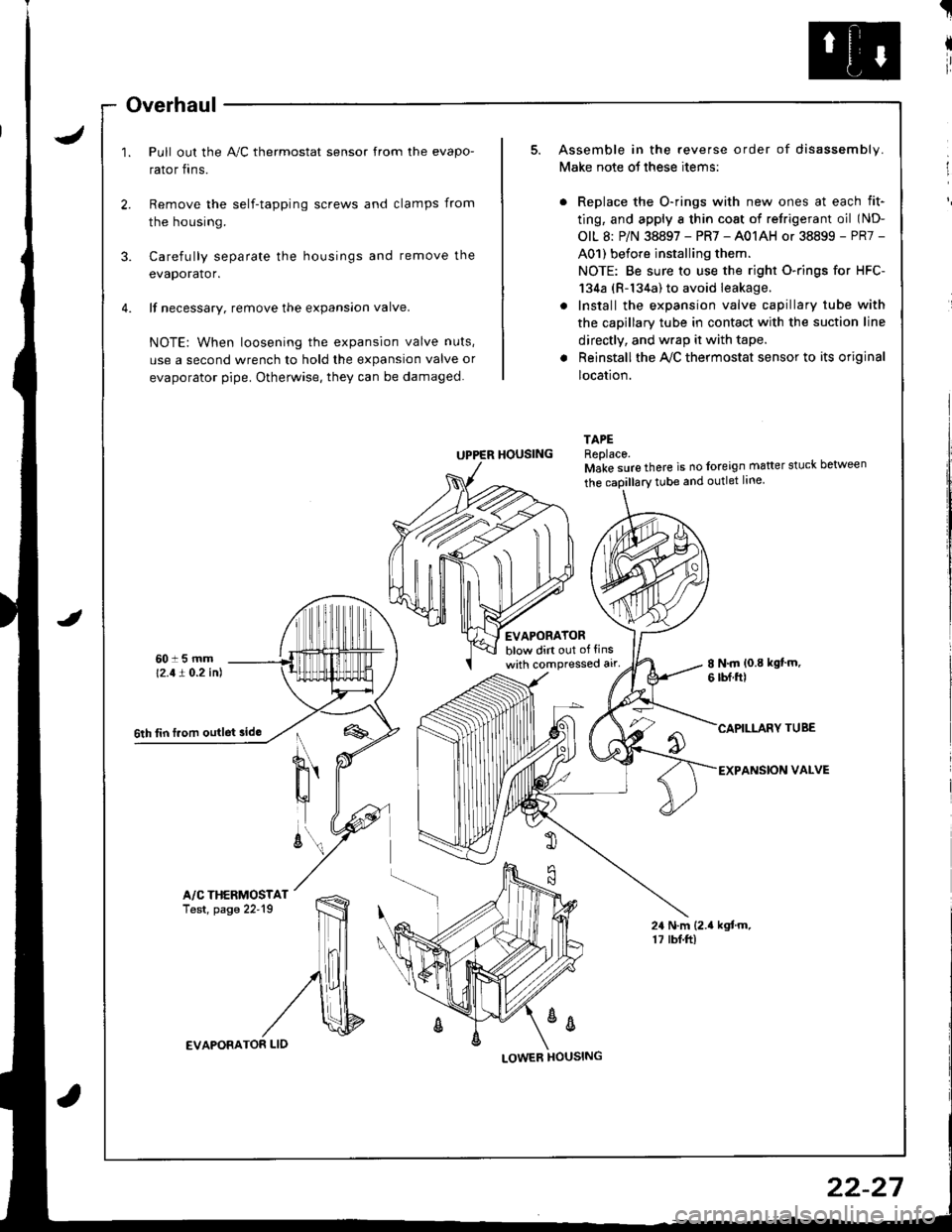
Overhaul
Pull out the A,/C thermostat sensor from the evapo-
rator fins.
t
I
ir
I
Remove the self-tapping screws and clamps from
the housing.
3. Carefully separate the housings and remove the
evaporator.
4. lf necessary. remove the expansion valve.
NOTE: When loosening the expansion valve nuts,
use a second wrench to hold the expansion valve or
evaporator pipe. Otherwise, they can be damaged.
Assemble in the reverse order of disassembly.
Make note ot these items:
Replace the O-rings with new ones at each fit-
ting, and apply a thin cost of retrigerant oil (ND-
OIL 8: P/N 38897 - PR7 - A01AH or 38899 - PR7 -
A01) before installing them.
NOTE: Be sure to use the right O-rings for HFC-
134a (R-134a) to avoid leakage.
Install the expansion valve capillary tube with
the capillary tube in contact with the suction line
directly, and wrap it with tape.
Reinstall the Ay'C thermostat sensor to its original
location.
TAPEReplace.Make sure there is no foreign matter stuck between
tEVAPORATORblow dirt out of tinswith compressed alr'8 N.m {0.8 kgt'm.6 rbf.ftl
CAPILLARY TUBE
EXPANSION VALVE
24 N.m (2.{ kgtm.17 rbf.ftl
UPPER HOUSING
%
6th tin f.om outlet sido
A/C THERMOSTATTest, page 22'19
EVAPORATOR LID
22-27
Page 1046 of 1680
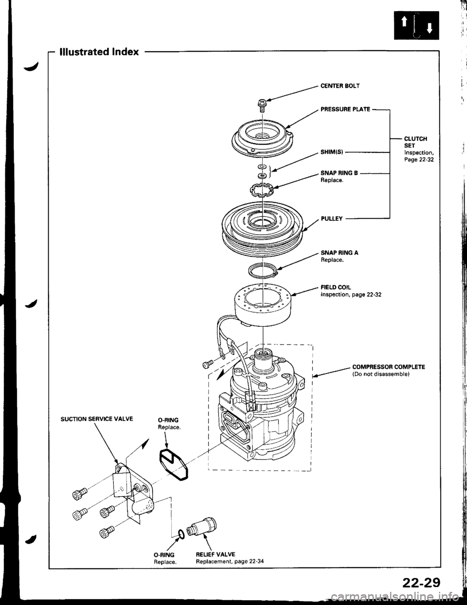
lllustratedlndex
CLUTCHSETlnspection,Page 22-32
SNAP RING AReplace.
FIELD COILInspection, page 22-32
I / COMPRESSOR COMPLETE
.-- lDo not disassemble)
SUCTION SERVICE VALVEO.RINGReplace.
I
S..-
VX
I
I ^.-{\
I.ory
O.RINGReplace.RELICF VALVER€placement. page 22-34
22-29
Page 1048 of 1680
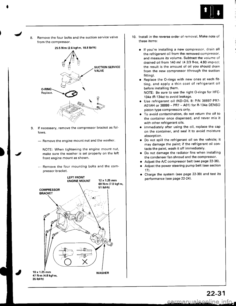
J8. Remove the four bolts and the suction servtce valve
from the compressor.
25.s18.8 tbf.ft)N.m {2.6 kgt.m,
A\
-/ l=\'zI
i:-
9.
SUCTION SERVICEVALVE
O-RING \Benrace. --'.l4p
lf necessary, remove the compressor bracket as fol
- Remove the engine mount nut and the washer'
NOTE: When tightening the engane mount nut,
make sure the washer is set properly on the left
front engine mount as shown.
- Remove the four mounting bolts and the com-
pressor bracket.
LEFT FRONTENGTNE MOUNT 12 x 1.25 mm
I
69 N.m {7.0 kg{.m.s1 rbt.ft)
10 x 1.25 mm47 N.m (4.8 kgf.m.35 rbf.ftt
10. lnstall in the reverse order of removal. Make note of
these rtems:
) lf you're installing a new compressor, drain all
the refrigerant oil from the removed compressor,
and measure its volume, Subtract the volume of
drained oil from 140 m{ 14 2/3ll.oz,4.93 imp.oz);
the result is the amount of oil you should drain
from the new compressor (through the suction
{itting).
r Replace the O-rings with new ones at each fit-
ting, and apply a thin coat of refrigerant oil
before installing them.
NOTE: Be sure to use the right O-rings for HFC-'t34a (R-134a) to avoid leakage.
. use refrigerant oil (ND-OlL 8: P/N 38897 PR7-
A0IAH or 38899 - PR7 - A01) for R-'134a DENSO
piston type compressors onlY.
. To avoid contamination, do not return the oil to
the container once dispensed, and never mix it
with other refrigerant oils.
. lmmediately after using the oil, replace the cap
on the container, and seal it to avoid moisture
aDsorDt|on.
. Do not spill the refrigerant oil on the vehicle; it
may damage the paint; if the refrigerant oil con-
tacts the Daint, wash it off immediately.
. Do not damage the radiator fins when installing
the condenser fan shroud and the compressor.
. Adjust the Ay'C compressoi belt {see page 22-36J
. Adjust the power steering pump belt (see section
17J.
. Charge the system (see page 22-39) and test its
performance {see Page 22-24).
WASHER
22-31