Page 891 of 1680
Moonroof
lndex
Hatchback
CAELE ASSEMBLYReplacement, page 20-81SUNSHAOEReplacement, page
MOTOBReplacement, page 20-80
GLASS BRACKETReplacement, page 20 81
SUNSHADE RAIL
FRONT DRAINCHANNELDRAIN CHANNEL
FRAME SEAL
FRONT DRAIN TUBE
V,
/
SLIDE STOPPERLINK
FRAMEReplacement, page 20 80
FRONT RAILHOLDER
REAR DRAIN TUSE
GUIDE RAILReplacement, page 20 81
(@
II RIGHT REARllj DRA|N vaLVE.fr/
,rr, ^*^/& IDRAIN VALVE I
[il
ir/l
@'\'FRoNT DRATNVALVE
20-77
Page 894 of 1680

Moonroof
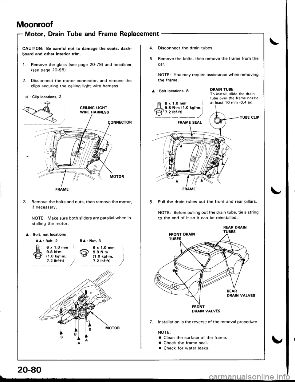
Motor, Drain Tube and Frame Replacement
CAUTION: Be careful not to damage the seats, dash-
boa.d and other interior trim.
1. Remove the glass (see page 20-79) and headliner
{see page 2O-98}.
2. Disconnect the motor connector, and remove the
clips securing the ceiling light wire harness.
Remove the bolts and nuts, then remove the motor,
if necessary.
NOTE: Make sure both sliders are parallel when in-
stalling the motor.
3.
: Bolt, nut locations
A
: 8olt, 2
6x 1.0mm I9.8Nm L
Nut, 3
6 x 1.0 mm I9.4 N.m
BA:
6@{1.0 kgf7 .2 tbl:!)(1.O kgf m, I
1'�lIltl /
< : Clip locations, 2
4,
FRAME
Oisconnect the drain tubes.
Remove the bolts, then remove the lrame from the
car.
NOTE: You may require assistance when removing
the trame.
A : Bolt locations, 8
TUBE CLIP
FRAME SEAL
Pull the drain tubes out the front and rear pillars.
NOTE: Before pulling out the drain tube, tie a string
to the end of it so it can be reinstalled.
REAR DRAINTUBES
7. Installation is lhe reverse of the removal procedure.
NOTE:
a Clean the surtace of the frame.
a Check the lrame seal.
a Check tor water leaks.
DRAIN TUBETo install, slide the draintube over the {rame nozzleat least 10 mm i0.4 in).
-'
6 x 1.0 mm9.8 N.m 11.0 kgt m,7.2 tbf.fr)
FRAME
FRONTDRAIN VALVES
!
\"
20-80
\
v
Page 898 of 1680
Moonroof
lndex
Sedan
GLASS BRACKETReplacement, page 20 88
SUNSHADEBeplacement, page
MOTORReplacement, page 20 87
FRONT DRAINCHANNEL
SUNSHADE RAIL
GUIOE RAILReplacemenl, page 20-88
REAR RAILHOLDER
SEAL
FRONT DRAIN TUBE
\,r,
r
/
REAR DRAIN TUBE
RIGHT REARORAIN VALVE
A FRONT ORAINq!-vawe
20-84
z=2,>
ORAIN CHANNEL
HoR I
v#,o**,"*
%bYP
FRAMEReplacement, page 20-87
\u 51-'--q€ \"
I
Page 901 of 1680

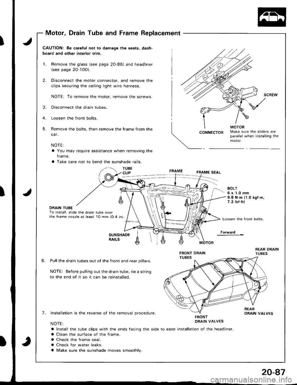
Motor, Drain Tube and Frame Replacement
J
J
CAUTION: Be ca.eful not to damage the seats, dash-
board and other interior trim,
1. Remove the glass (see page 2O-86) and headliner(see page 20- 1OO).
2. Disconnect the motor connector, and remove the
clips securing the ceiling light wire harness.
NOTE: To remove the motor, remove the screws.
3. Disconnect the drain tubes.
4. Loosen the front bolts.
5. Remove the bolts, then remove the frame from the
car.
NOTE:
a You may require assistance when removing the
f rame.
a Take care not to bend the sunshade rails.
TUBECLIP
CONNECTORMake sure the sliders areparallel when installing themotor.
FRAMEFRAME SEAL
DRAIN TUBETo Install, slide the drain tube overthe frame nozzle at least 10 mm (0.4 in).
EOLT6 x 1.0 mm9.8 N.m l1.O kgf .m,
7 .2 tbt.ltl
Loosen the front bolts,
Fo.ward
6.
7.
SUNSHADERAILS
Pull the drain tubes out of the front and rear pillars.
NOTE: Before pulling out the drain tube, rie a string
to the end oI it so it can be reinstalled.
Installation is the reverse ol the removal procedure.
NOTE:
a Install the tube clips with the ends {acing the side to ease
a Clean the surface of the frame.
a Check the frame seal.
a Check lor water leaks.
a Make sure the sunshade moves smoothly.
FRONTDRAIN VALVES
installation of the headliner.
Page 987 of 1680

iii
i
I
J
Heater
fffustrated Index ............. ......'..21-2
Heater Door Positions '....'........ 21-3
Circuit Diagram ....................... 21-6
Troubleshooting
Symptom Chart ............. '.....21-8
Flowcharts
Blower Motor Speed ...............'......'........ 21 -9
Blower Motor ............'......21-11
Mode Controf Motor ............ ............'... "' 21 -14
Recirculation Control Motor ......'...... "'.,.,. 21 -1 7
Heater Control Panel Input/
Output Signals ...'.......... 21-19
Blower Unit
Replacement ........ '....... ',..,.. 21-2O
Overhaul ",',..21-21
*Heater Unit
Repf acement .....'.....'........'.. 21'22
Overhaul .......21-24
Heater Control Panel
Repfacement ....... '..... '......... 21-25
Overhaul .......21-26
Heater Valve Cable
Adjustment '.. 21'27
Air Mix Control Cable
Adiustment ... 21-27
Mode Control Motor
Test .............. ..................... 21'24
Repfacement ....................... 21-24
Recirculation Control Motor
Test .............. ..................... 21-29
Repf acement .........'........ " ". 21-29
Relay
Test .............. ..................... 21-3O
Heater Fan Switch
Test .............. ....................' 21-30
Mode Control Switch
Test .............' "'..............'... 21-31
Recirculation Control Switch
Test .............. ..................... 21-31
*: Read SRS precautions before working in this area.
Page 988 of 1680
lllustrated Index
SRS components are located in this area. Review the SRS component locations. precautions, and procedures in the SRSsection (23) before performing repairs or service.
BLOWER UNITReplacement, page 21-2OOverhaul, page 21.21
HEATER VALVE CABLEAdiustment, page 21-27
HEATER UNITReplacement, page 21-22Overhaul, page 21-24RECIRCULATION CONTROL MOTORIest, page 21,29Seplacement, page 21-29
BLOWER RESISTORTest, page 21-9
AIR MIX CONTROLCABLEAdjustment, page 21-27Replacement, page 21-26
A/C SWTTCH{with A/clTest, page 22-20
RECIRCULATIONCONTROL SWITCHTest, page 21,31
HEATER FANswrTcHTest, page 21-30
MODE CONTROL MOTORTest, page 21-28Replacement, page 2 l -28CONTROL SWITCHTest, page 21-3'l
HEATER CONTROL PANELReplacement, page 21,25Overhaul, page 21-26
TEMPERATURE CONTROLLEVERlAdjustment: Soe AIR MIXCONTROL CABLEI
21-2
Page 994 of 1680

SYMPTOMREMEDY
Hot air tlow is low.Blower motor runs, but one or more
speeds are inoperative.
Follow the flowchart (see page 21-9).
Blower runs propetly.Check for the following:. Clogged heater duct
. Clogged heater outlet
. Incorrect door Position
No hot air tlowBlower motor does not run at all.Follow the flowchart {see page 21-11}
Blower motor runs.Check for the following:
. clogged heater duct
. Clogged blower outlet. Clogged heatet valve
. Faultv air mix door
. Heater valve cable adjustment lsee page 21-27].
. Air mix control cable adiustment {see page 21-27)
. Faulty thermostat (see section 10)
. Clogged evsporator (with air conditioning)
. Frozen evaDorator (with air conditioning)
Mode control motor does not run, or one or more mooes are
inoDeratave.
Follow the flowchart (see page 21-14).
Recirculation control door does not change between FRESH
and RECIRCULATE.
Follow the flowchart {see page 21-17).
Troubleshooting
Symptom Chart
NOTE: Check the engin€ coolant level and allow the engine to warm up before troubleshooting'
21-8
v
Page 1008 of 1680

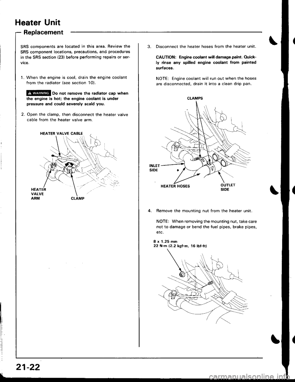
Heater Unit
Replacement
SRS components are located in this area. Review the
SRS component locatio.s, precautions, and procedures
in the SRS section (23) before performing repairs or ser-
vtce.
1. When the engine is cool, drain the engine coolant
from the radiator (see section 1O).
@ oo not remove the radiator cap when
the engine is hot; the engine coolant is undol
prsssure and could sevdely scald you.
2. Ooen the clamD, then disconnect the heater valve
cable from the heater valve arm.
HEATER VALVE CABI-E
I
i
21-22
3. Disconnect the heater hoses lrom the heater unit.
CAUTION: Engine coolant will damaga paint. Ouick-
ly rinse any spilled engine coolant from painted
sudaces.
NOTE: Engine coolant will run out when the hoses
are disconnected, drain it into a clean drip pan.
4. Remove the mounting nut from the heater unit.
NOTE: When removing the mounting nut, take care
not to damage or bend the fuel pipes, brake pipes,
etc.
8 x 1.25 mm22 N'llt. 12.2 kgl'm, 16 lbl.tl)
CLAMPS
HEATER HOSES