1998 ACURA INTEGRA valve
[x] Cancel search: valvePage 706 of 1680

Power Steering Gearbox
Reassembly (cont'dl
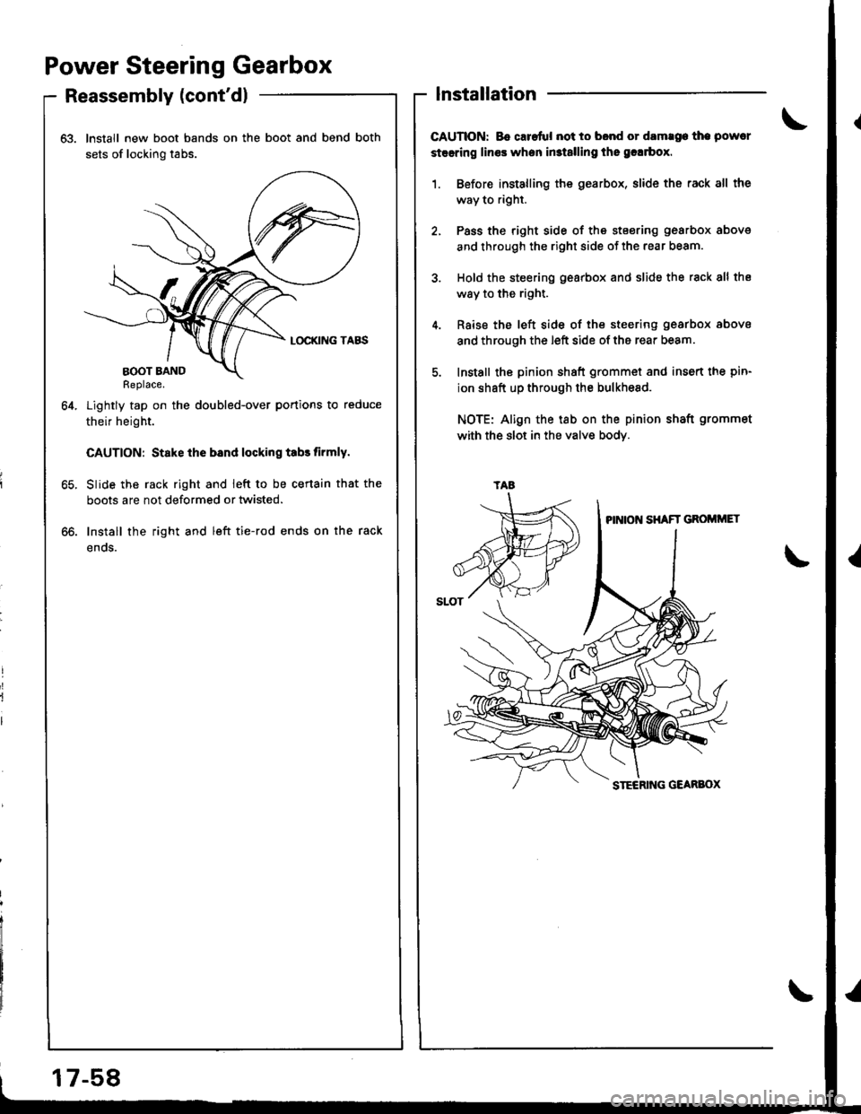
63. Install new boot bands on the boot and bend both
sets of locking tabs.
Lightly tap on the doubled-over portions to reduce
their height.
CAUTION: Stake ihe bsnd locking tabs tirmly.
Slide the rack right and ieft to be certain that the
boots are not deformed or twisted.
Install the right and left tie-rod ends on the rack
enos.
64.
lnstallation
CAUTION: Bo caretul not to bond or damrge the powcr
steering lines when in3t8lling the grlrbox.
1. Before installing the gearbox, slide the rack all the
way to right.
2, Pass the right side of the stsering gearbox above
and through the right side of the rear beam.
3. Hold the steering gearbox and slide the rack 8ll the
way to the right.
4. Rsise the left side of the steering gearbox above
and through the left side of the rear beam.
5. Install the pinion shaft grommet and insert the pin-
ion shaft up through the bulkhesd.
NOTE: Align the tab on the pinion shaft grommet
with the slot in the valve bodY.
oo.
tAa
17-58
Page 707 of 1680

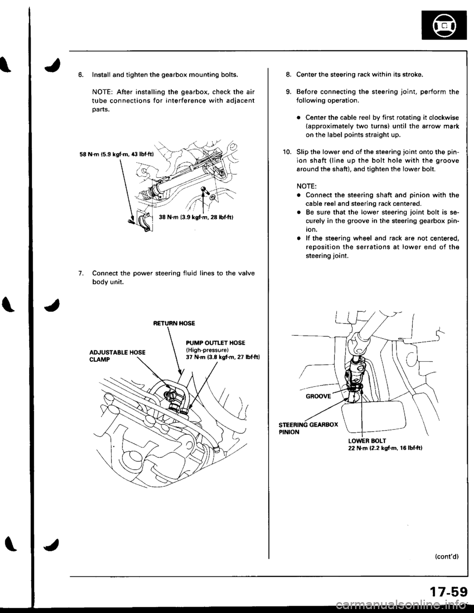
Install and tighten the gearbox mounting bolts.
NOTE: After installing the gearbox, check the air
tube connections for interference with adjacent
parts.
58 N.m 15.9 kgl.m, 43 lbf.ftl
Connect the power steering fluid lines to the valve
body unit.
7.
38 N.m {3.9 kgt m, 28 lbf.ftl
RETURN HOSE
PUMP OUTI.TY HOSE(High-pressure)
37 N.m (3.8 kgf.m, 27 lbt.ftl
Center the steering rack within its stroke.
Before connecting the steering joint, perform the
lollowing operation.
. Center the cable reel by first rotating it clockwise(approximately two turns) until the arrow mark
on the label points straight up,
Slip the lower end of the steering ioint onto the pin-
ion shaft {line up the bolt hole with the groove
around the shaft), and tighten the lower bolt.
NOTE:
. Connect the steering shaft and pinion with the
cable reel and steering rack centered.
. Be sure that the lower steering joint bolt is se-
curely in the groove in the steering gearbox pin-
ion.
o lf the steering wheel and rack are not centered,
reoosition the serrations at lower end of the
steering joint.
(cont'd)
LOWER BOLT22 N.m {2.2 kgf.m, 16 lbf.ft,
17-59
Page 766 of 1680

1.
8.
NOTE: lf the clearance between the gauge body
and adjusting nut is 0.4 mm (0.02 in), the pushrod-
to-piston clearance is 0 mm. However, if the clear-
ance between the gauge body and adjusting nut is
0 mm, the pushrod-to-piston clearance is 0.4 mm(0.02 in) or more. Therefore it must be adjusted and
rechecked.
lf clearance is incorrect, loosen the star locknut and
turn the adjuster in or out to adjust.
NOTE:
. Adjust the clearance while the specified vacuum
is applied to the booster.
. Hold the clevis while adjusting.
Tighten the star Iocknut securely.
Remove the special tool.
0 - o.il mm l0 - 0.02 inl
Brake Booster Inspection
Functions Tgst
1. With the engine stopped, depress the brake pedal
several times to deplete the vacuum reservoir, then
depress the pedal hard and hold it for 15 seconds. ll
the pedal sinks, either the master cylinder is
bypassing internally; or the brake system (master
cylinder, lines, modulator proportioning valve, orcaliper) are leaking.
Start the engine with the pedal depressed. lf thepedal sinks slightly, the vacuum booster is operat-
ing normally. lf the pedal height does not vary, the
booster or check valve is faulty.
With the engine running, depress the brake pedal
lightly. Apply just enough pressure to hold back
automatic transmission creep, lf the brake pedal
sinks more than 25 mm (1.0 in.) in three minutes,
the master cylinder is faulty. A slight change inpedal height when the A,,/C compressor cycles on
and off is normal. (The A/C compressor load
changes the vacuum available to the booster.)
Leak Test
1. Depress the brake pedal with the engine running,
then stop the engine. lf the pedal height does not
vary while depressed for 30 seconds, the vacuum
booster is OK. lf the pedal rises, the booster is
fau lty.
2. With the engine stopped, depress the brake pedal
several times using normal pressure. When thepedal is first depressed, it should be low. On con-
secutive applications, the pedal height should grad-
ually rise. lf the pedal position does not vary, check
the booster check valve.
Boostor Ch€ck Valve T6st
1. Disconnect the brake booster vacuum hose at the
booster,
Start the engine and let it idle. There should be vac-
uum available. It no vacuum is available. the check
valve is not working properly. Replace the brake
booster vacuum hose and check valve, and retest.
VACUUM HOSE(Check valve built-in)
STAR LOCKNUT22 t{.m12.2 ksl.m, 16lbf.ftl
cLEVtS
ADJUSTER
ADJUSTMENT GAUGE07JAG - SD40t00
9. Adjust the pushrod length as shown if the booster
is removed.
1161 0.5 mm14.61 0.02 inl
PUSHRODLOCKNUT15 N m 11.5 kgf m, 11 lbf'ftl
10. Instali the master cylinder.
Page 778 of 1680

IABS Control
The ABS control unit detects the wheel speed based on the wheel sensor signal it received, then it calculates the vehiclespeed based on the detected wheel speed. The control unit detects the vehicle speed during deceleration based on therate of deceleration.
The ABS control unit calculates the slip rate of each wheel, and it transmits the control signal to the modulator unitsolenoid valve when the slip rate is high.
The pressure reduction control has three-modes: pressure reduction, pressure retaining, and pressure intensifying.
Self-diagnosis Function
The CPUS in the ABS control unit check the circuit of the system.
The self-diagnosis can be classifield into two categories.. Initial diagnosis: Performed right after the engine starts and until the ABS indicator gose off.. Regular diagnosis: Performed right after the initial diagnosis until the ignition switch isturnedoff.
On-board Diagnosis Function
The ABS control unit is connected to the data link connector fi6p).The ABS system can be diagnosed with the Honda PGM Tester.
(cont'd)
19-27
Page 779 of 1680

Anti-lock Brake System (ABS)
Features/Construction (cont'd)
ABS Modulatol
The ABS modulator consists of the inlet solenoid valve, outlet solenoid valve, reservoir, pump, pump motor and the
damping chamber.
The modulator reduces the caliper fluid pressure directly. lt is a circulating-type modulator because the brake fiuid circulates
through the caliper, reservoir and the master cylinder.
The hydraulic control has three modes: pressure reduction, pressure retaining and pressure intensiiying
The hvdraulic circuit is the independent four channel-type, one channel tor each wheel'
L-__
RF LR
Pressure intensifying mode: Inlet valve open, outlet valve closed
Master cvlinder fluid is pumped out to the caliper.
Inlet valve closed, outlet valve closed
Caliper fluid is retained by the inlet valve and outlet valve.
lnlet valve closed, outlet valve open
Caliper fluid flows through the outlet valve to the reservolr'
When starting the pressure reduction mode, the pump motor is ON.
When stopping ABS operation, the pump motor is OFF.
The reservoir fluid is pumped out by the pump, through the damping chamber, to the master
cylinder.
\
Pressure retaining mode:
Pressure reduction mode:
Motor operation mode:
sott orD vALvE
@@-@@
TASIEF CYLI'OEF
19-24
Page 780 of 1680

Wheel Speed and Modulator Control
OUTLETVALVE oN
OFF
INLETVALVE ON
OFF
MOTOR
ON
OFF
When the wheel speed drops sharply below the vehicle speed, the inlet valve closes to retain the caliper fluid pressure.
When the wheel speed drops further, the outlet valve opens momentarily to reduce the caliper fluid pressure. The pump
motor starts at this time.
As the wheel speed is restored, the inlet valve opens momentarily to increase the caliper fluid pressure.
Wheel Sensor
The four wheel sensors are the magnetic contactless type. As the gear pulser teeth rotate past the wheel sensor's magnetic
coil, AC current is generated. The AC frequency changes in accordance with the wheel speed. The ABS control unit detects
the wheel sensor signalfrequency and thereby detects the wheel speed.
rr LOW SPEED
5
GEAR PUTSER
19-29
Page 785 of 1680

ABS Control Unit Terminal Arrangement
ABS CONTROL UNIT 12P CONNECTOR
Wire side of female terminals
Terminal
number
Wire
colot
Terminal sign
(Tsrminal
name,
Doscription
Measuromgnt
TerminalConditions
{lgnhion switch ON {ll)}Voltage
BLU/RED(Warning
ramp,
Drives ABS indicator
1.GNDABS indicatorON3-6V
OFFBelow 0.3 V
,BLKGNDl
{Ground 1)
Ground2-GNDBelow 0.3 V
BLI(ORN
RR-OUT(Rear-right
outlet)
Drives right-rear outlet
solenoid valve3-GND
a
OFFBattery voltage
YEUBLU
FL.OUT(Front-left
outlet)
Drives left-front outlet
solenoid valve4-GND
YEL/WHT
RL-OUT(Rearleft
outlet)
Drives left-rear outlet
solenoid valve5.GND
ONBelow 0.3 V
YEUBLK
FR-OUT
(Front-right
outlet)
Drives right-front outlet
solenoid valve6-GND
7BLKGND2
(Ground 2)
G rou nd7-GNDBelow 0.3 V
8YEL
RR-IN(Rear-right
inlet)
Drives right-rear inlet
solenoid valve8.GND
.9
-@
OFFBattery voltage
IRED/B LU
FL-IN(Front-left
inlet)
Drives left-front inlet
solenoid valve9-GND
l0RED/WHT
RL-IN
{Rearleft
inlet)
Drives left-rear inlet
solenoid valve1O-GND
ONBelow 0.3 V
11RED/BLK
FR] N(Front-right
inlet)
Drives right-front inlet
solenoid valve11-GND
't2YEURED
PMR
{Pump motor
retay)
Drives pump motor relay
12-GND.9
.EU'@
OFFdE
ONBelow 1.0 V
OFFBattery voltage
ONBelow 0.3 V
19-34
Page 786 of 1680

Troubleshooting Precautions
ABS lndicator
1. lf the system is OK. the ABS indicator goes off two seconds after turning the ignition switch ON (ll) without starting
the engine, and then comes on again and goes off after two seconds. This occurs because the ABS control unit is
turned on bv the lG2 oower source.
2. The ABS indicator comes on when the ABS control unit detects a problem in the system. However, even though the
system is operating properly, the ABS indicator will come on under the following conditions.. Onlv drive wheels rotate
. One drive wheel is stuck
. Vehicle spin
. ABS continues to operate for a long time
. Signal disturbance
To determine the actual cause of problem. question the customer about the problem, taking these conditions into
consideration.
3. When a problem is detected and the ABS indicator comes on, there are cases when the indicator stays on until the
ignition switch is turned OFF, and cases when the indicator goes off automatically when the system returns to nor-
mal. For DTCS 61 and 62, the indicator goes off automatically when the system returns normal. For all other codes.
the indicator stays on until the ignition switch is turned OFF.
4. For DTCS 12, 14, 16, '18, 2'1,22, 23, 24,51,52 and 53, the indicator goes off when the vehicle is driven again and the
system is OK after the ignition switch is turned from OFF to ON (ll). However, if the DTC is erased, the CPU is reset
and the indicator goes off right after the engine is started if the system is OK.
Diagnostic Trouble Code (DTC)
1. lf the CPU cannot be actlvated and the indicator comes on, the DTC is not memorized.
2. The memory can hold any number of DTCS. However, when the same DTC is detected more than once, the later one
is written over the old one. Therefore, when the same problem is detected repeatedly, it is memorized as one DTC.
3. The DTCs are indicated in the order of ascending number, not in the order they occur.
4, The DTCS are memorized in the EEPROM (non-volatile memory). Therefore, the memorized DTCS cannot be canceled
by disconnecting the battery. Perform the specified procedures to erase the DTCS,
S6lt-dirgnosis
1. Self-diagnosis can be classifield into two categories.
. Initial diagnosis: Performed right afterthe enginestansand untiltheABS indicator goes off.. Regular diagnosis: Performed rightafterthe initial diagnosis untilthe ignition switch isturned OFF.
2. When a problem is detected by self-diagnosis, the system
. Turns the fail-safe relay OFF
. Turns the solenoid valve OFF
. Turns the oumo motor OFF
. Turns the ABS indicator ON