1998 ACURA INTEGRA valve
[x] Cancel search: valvePage 566 of 1680
Glutch
Reassembly
NOTE:
a Clean all parts thoroughly in solvent or carburetor
cleaner, and dry them with compressed alr.
a Blow out all passages.
a Lubricate all parts with ATF belore reassembly.
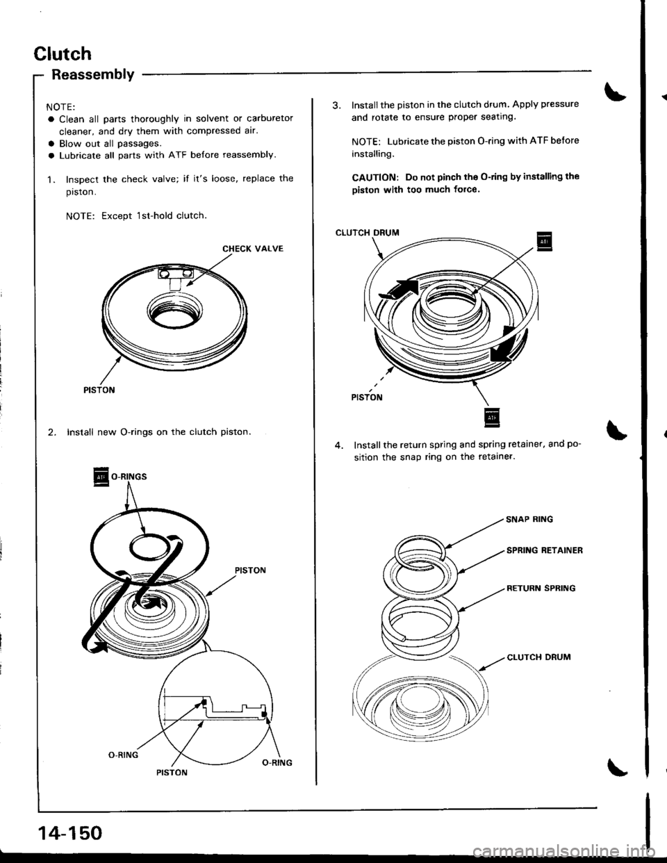
1. Inspect the check valve; if it's loose, replace the
prston.
NOTE: Except 1sr-hold clutch
CHECK VALVE
PISTON
14-150
3. Installthe Diston in the clutch drum. Apply pressure
and rotate to ensure proper seating.
NOTE: Lubricate the piston O-ring with ATF before
installing.
CAUTION: Do not pinch tho O-ring by installing the
piston with too much force'
CLUTCH DRUM
Installthe return spring and spring retainer. and po-
sition the snap ring on the retaine..
CLUTCH DRUM
Page 575 of 1680
Transmission
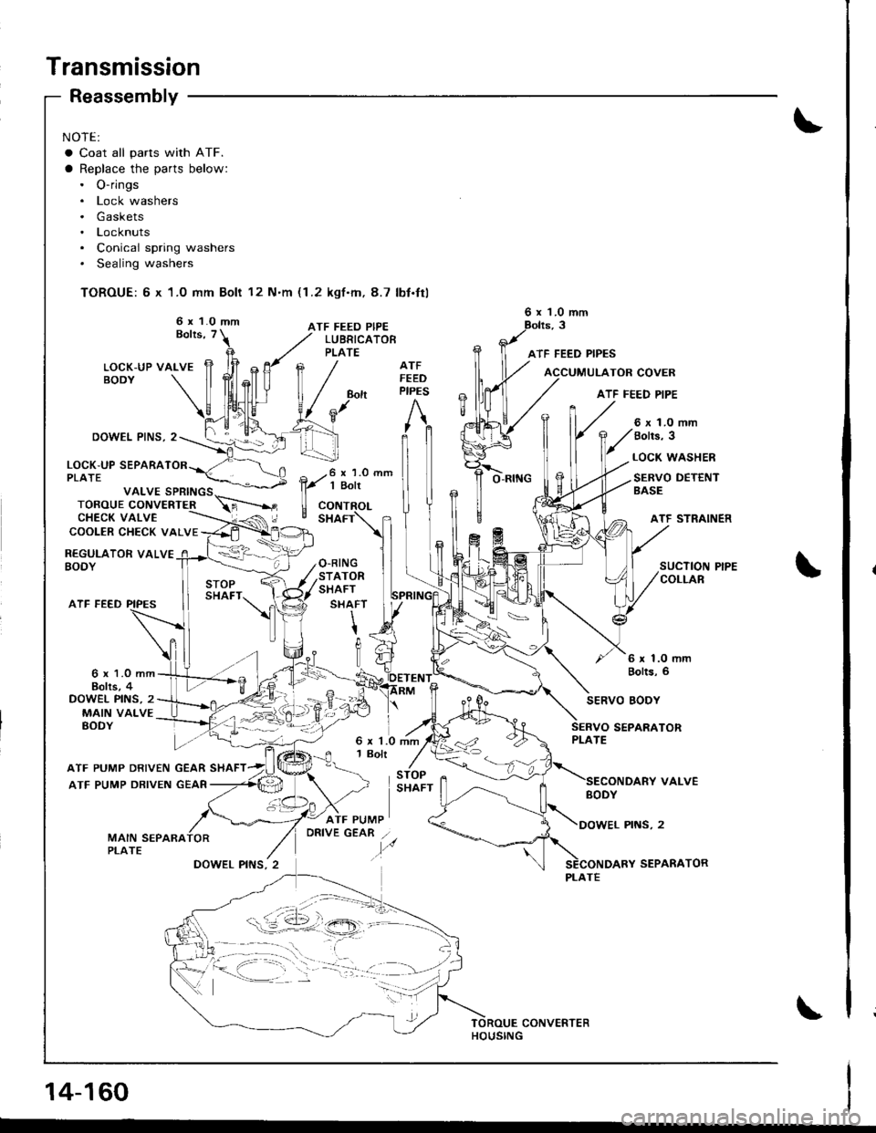
NOTE:
a Coat all parts with ATF.
a Replace the parts below:. O-rings. Lock washers. Gaskets. Locknuts. Conical spring washers. Sealing washers
TOROUE: 6 x 1.0 mm Bolt 12 N'm (1.2 kgf.m, 8.7 lbt.ttl
6 x 1.0 mmATF FEED PIPEBolts, T
Reassembly
DOWEL PINS, 2
ATF FEED
LUBRICATOBPLATE
6 x 1.0 mm
ATF FEED PIPES
O.RINGSTATORSHAFT
SHAFT
\tIt]U
ATFFEEDPIPES
STOPSHAFT
6 x 1.0 mmBolts, 6
TOR COVER
ATF FEED PIPE
VALVE SPRINGSTOROUE CONVERTERCHECK VALVECOOLER CHECK VALVE
LOCK-UP SEPARATPLATE
REGULATOR VALVEBODY
6 x 1.0 mm8olls, 3
LOCK WASHER
SERVO DETENTBASE
ATF STRAINER
SUCTION PIPECOLLAR
6 x 1.0 mmBohs, 4DOWEL PINS, 2MAIN VALVEBODY
SERVO EODY
SEPARATOR
VALVE
PINS,2
SEPARATOR
6 x 1.0 mm1 Bolt
ATF PUMP DRIVEN GEAR SHAFT
ATF PUMP DRIVEN GEAR
GEAR /.
.,,o
{--==,.-,,..;;,,, :_ :,_11,
PLATE
14-160
CONVERTER
Page 576 of 1680
)
)
A
1.
ATF PUMP DRIVENGEAR SHAFT
ATF PUMPDRIV€N GEAR
J.
6
Grooved and ch6mleredside faces separatorplate.
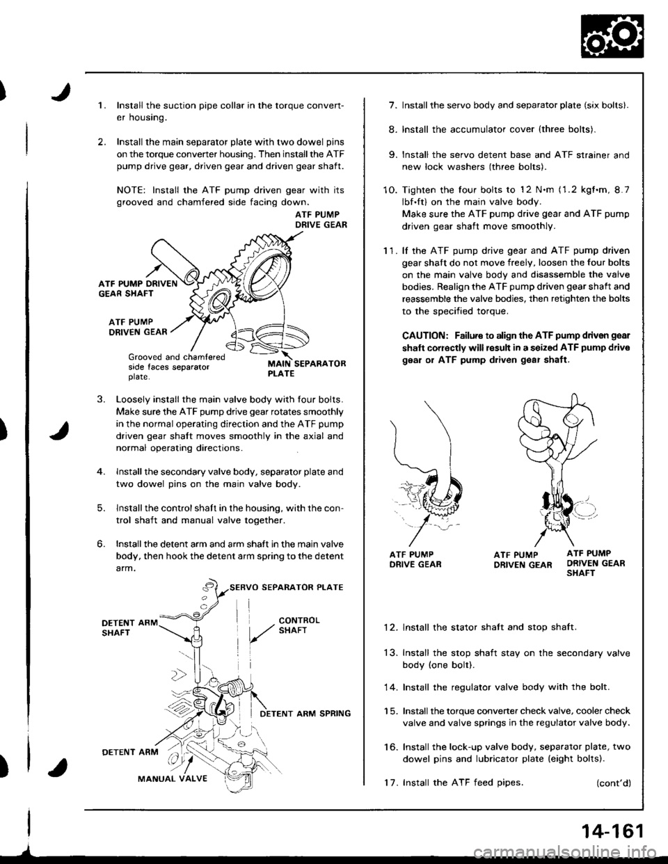
Install the suction pipe collar in the torque conven-
er housing.
Install the main separator plate with two dowel pins
on the torque convener housing. Then install the ATF
pump drive gear, driven gear and driven gear shaft.
NOTE: Install the ATF pump driven gear with its
grooved and chamfered side facing down.
ATF PUMPDRIVE GEAR
Loosely install the main valve body with four bolts.
Make sure the ATF pump drive gear rotates smoothly
in the normal operating direction and the ATF pump
driven gear shalt moves smoothly in the axial and
normal operating directions.
Install the secondary valve body, separator plate and
two dowel pins on the main valve body.
lnstallthe control shaft in the housing, with the con-
trol shaft and manual valve together.
Installthe detent arm and arm shaft in the main valve
body, then hook the detent arm spring to the detent
arm.
SERVO SEPARATOR PLATE
I
DETENT ARM SPRING
'17. Install the ATF feed oipes.
14-161
7. Install the servo body and separator plate (six bolts|.
8. Install the accumulator cover (three bolts).
9. Install the servo detent base and ATF strainer and
new lock washers (three bolts).
1O. Tighten the four bolts to '12 N.m (1.2 kgt.m, 8.7
Ibf.ft) on the main valve body.
Make sure the ATF pump drive gear and ATF pump
driven gear shaft move smoothly.
11. lf the ATF pump drive gear and ATF pump driven
gear shaft do not move freely, loosen the four bolts
on the main valve bodv and disassemble the valve
bodies. Realign the ATF pump driven gear shaft and
reassemble the valve bodies, then retighten the bolts
to the soecified toroue.
CAUTION: Failure to align the ATF pump ddven gear
shaft corr€ctly will result in a seized ATF pump driv€
gear or ATF pump dliven g€ar shatt,
ATF PUMP ATF PUMP
DRtvEN GEAR ORIVEN GEARSHAFT
12. lnstall the stator shatt and stop shaft.
13. Inslall the stop shaft stay on the secondary valve
body (one bolt).
14. Install the regulator valve body with the bolt.
1 5. Install the torque converter check valve, cooler check
valve and valve springs in the regulator valve body.
16. Install the lock-up valve body, separator plate, two
dowel pins and lubricator plate (eight bolts).
(cont'd)
Page 586 of 1680

I20.Connect the vehicle speed sensor (VSS), mainshaft
speed sensor, and countershaft sDeed sensor con-
nectors.
VEHICLE SPEED SENSORCONNECTOB
)
k/
t"J
21. Connect the lock-up control solenoid valve connec-
tor and shift control solenoid valve conneclor, then
clamp the lock-up control solenoid harness with the
harness bracket.
22. Connect the transmission ground cable.
SPEED SENSOR
LOCK-UP CONTROLSOLENOID VALVECONNECTOR
23.Connect the starter cable to the starter motor, and
install the cable holder.
NOTE: When installing the starter motor cable,
make sure that the crimped side ol the ring terminal
is facing out (see section 23).
6 x 1.0 mm12 N.m {1 .2 kgf.m, 8.7 lbl.ft)
9 N.m(0.9 kgf.m, 7 lbt.ttl
STARTER CABLETERMINAL
STARTER CABLE
24.Install the air cleaner housing assembly and intake
arr oucl.
AIR CLEANER HOUSINGINTAKE AIRASSEMBLY
27.
Refill the transmission with ATF {see page 14-98).
Connect the battery positive (+ ) and negative { - }cables to the battery.
Start the engine. Set the parking brake, and shift the
transmission through all gears three times.
Check shilt cable adjustment as described on page
14-176.
Check the front wheel alignment (see section 18).
Let the engine reach operating temperature (the cool-ing fan comes onl with the transmission in S or @position, then turn it off and check the fluid level.
31. Road test as described on page 14-94 and 96.
25.
26.
24.
29.
30.
14-171
Page 587 of 1680
Transmission
Cooler Flushing
S@ to pttvont iniury to face and syes' always
w6ar safety glassos or a face shield when using the trans-
mission flusher.
NOTE: This procedure should be performed before rein-
stalling the transmission.
1. Check tool and hoses for wear and cracks before
using. lf wear or cracks are found, replace the hoses
before using.
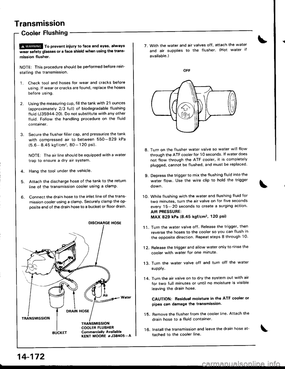
2. Using the measuring cup, fill the tank with 21 ounces
(approximately 2/3 full) of biodegradable tlushing
fluid {J35944-20). Do not substitute with any orher
tluid. Follow the handling procedure on the tluid
contalner.
3. Secure the flusher filler cap, and pressurize the tank
with compressed air to between 550-829 kPa
{5.6-8.45 kgf /cm'�, 80- 120 Psi}.
NOTE: The air line should be equipped with a water
trap to ensure a dry air system.
4. Hang the tool under the vehicle
5. Attach the discharge hose of the tank to the return
line oI the transmission cooler using a clamp
6. Connect the drain hose to the inlet line of the trans-
mission coolel using a clamp. Securely clamp the op-
oosite end of the drain hose to a bucket or tloor drain.
DRAIN HOSE
TRANSMISSION
TRANSMISSIONCOOLER FLUSHERComm6rci.llY Av.ilabloKENT MOORE #J3A/O5_A
DISCHARGE HOSE
14-172
BUCKET
7. With the water and air valves ofl, atach the water
and air supplies to the flusher. (Hot water if
available.)
8. Turn on the flusher water valve so water will flow
through the ATF cooler for 10 seconds. lf water does
not flow through the ATF cooler, it is completely
plugged, cannot be flushed, and must be replaced
9. Depress the trigger to mix the flushing fluid into the
water flow. Use the wire clip to hold the trigger
oown.
1O. While tlushing with the water and llushing f luid for
two minutes. turn the air valve on for five seconds
everv 15-20 seconds to create a surglng actlon.
AIR PRESSURE:
MAX 829 kP8 18.45 kgf/cm'�, 120 Psil
1 1. Turn the water valve off. Release the trigger. then
reverse the hoses to the cooler so you can flush in
the ooDosite direction. Repeat steps 8 through 1O.
12, Release the trigger and allow water only to rinse the
cooler with water for one minute.
13. Turn the water valve oJf and turn off the water
supply.
'14. Turn the air valve on to dry the system out with air
for two full minutes or until no moisture is visible
leaving the drain hose.
CAUTION: Residual moisture in the ATF coolei 01
pipos can damage the transmission.
15. Remove the flusher {rom the cooler line. Attach the
drain hose to a fluid contaaner.
16. Installthe transmission and leave the drain hose a1-
tached to the cooler line.
Page 650 of 1680
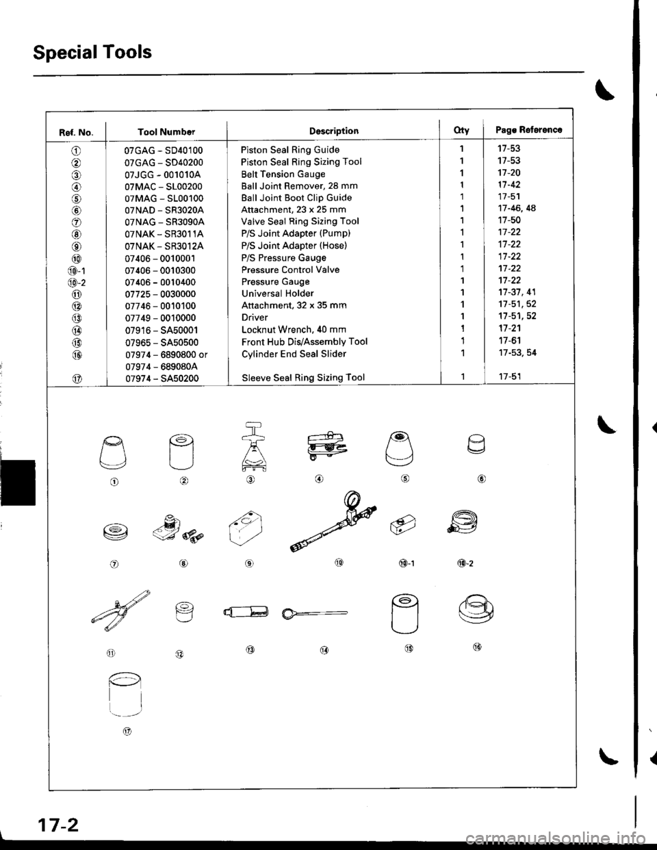
SpecialTools
{
\
\
17-2
Ref. No. I Tool NumberDsscriptionOty I Pags Reterenc.
o
@
@
o
@
@
@
@
@
@-1
@-2
o6:^
@
@
@
@
@
07GAG - SD40100
07GAG - SD40200
07JGG - 001010A
07MAC - S100200
07MAG - S100100
07NAD - SR3020A
OTNAG _ SR3OgOA
OTNAK - SR3O11A
OTNAK - SR3O12A
07406 - 0010001
07406 - 0010300
07406 - 0010400
07725 - 0030000
07746 - 0010100
07749 - 0010000
07916 - SA50001
07965 - SA50500
07974 - 6890800 or
07974 - 6890804
07974 - SA50200
Piston Seal Ring Guide
Piston Seal Ring Sizing Tool
Belt Tension Gauge
Ball Joint Remover, 28 mm
Ball Joint Boot Clip Guide
Attachment, 23 x 25 mm
Valve Seal Ring Sizing Tool
P/S Joint Adapter (Pump)
P/S Joint Adapter (Hose)
P/S Pressure Gauge
Pressure Control Valve
Pressure Gauge
Universal Holder
Attachment, 32 x 35 mm
Driver
Locknut Wrench. 40 mm
Front Hub Dis/Assembly Tool
Cylinder End Seal Slider
Sleeve Seal Ring Sizing Tool
'I
1
1
1
1'|
1,l
I
1
1
1'I
'l
1
1
1
1
1
't7-53
17-53't]-20
11-42
17 -51
17 -46, 4A
17-50
17-37, 41
11-51,52't1-51,52
17 -2'�1
17 -6'l
17-53. 54
17-51
o
L'4,
o
€)
-g)c-J 8p
@
@
6i
(9')\E/'
@-t
a
6
ffi
@-z
d--E ia*=-
o
l-l
t..-_-.r
A)
@@@
\
Page 652 of 1680

System Description
Fluid Flow Diagram
The system is a compact rotary-valve-type power steering, connected to the steering gearbox. The fluid pressure is pro-
vided by a vane-type pump which is driven by the engine crank pulley. The amount of fluid and pressure is regulated by
the flow control valve built into the pump. The fluid pressure from the pump is delivered to the valve body unit around the
pinion of the steering gearbox. The valve inside the valve body unit controls the hydraulic pressure and changes the direc-
tion of the tlow. The fluid then flows to the power cylinder, where rack thrust is generated. Fluid returning from the power
cylinder flows back to the reservoir, where the fluid is "filtered" and supplied to the pump again
li
I
VALVE BODY UNIT
GEARBOXFLOW CONTROL VALVEPOWER CYLINDER
17-4
Page 653 of 1680
Steering Pump
Construc'tion
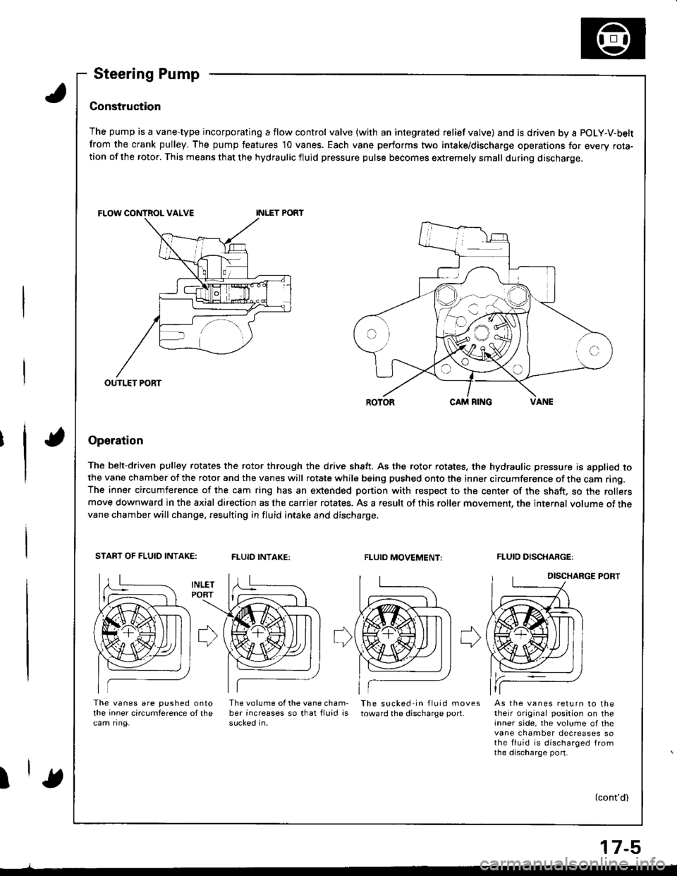
The pump is a vane-type incorporating a flow control valve (with an integrated relief valve) and is driven by a POLY-V-belt
from the crank pulley. The pump features 10 vanes. Each vane performs two intake/discharge operations for every rota-tion of the rotor. This means that the hydraulic fluid pressure pulse becomes extremely small during discharge.
Operation
The belt-driven pulley rotates the rotor through the drive shaft. As the rotor rotates. the hydraulic pressure is applied tothe vane chamber of the rotor and the vanes will rotate while being pushed onto the inner circumference of the cam ring.The inner circumference of the cam ring has an extended portion with respect to the center of the shaft, so the rollersmove downward in the axial direction as the carrier rotates. As a result of this roller movement, the internal volume of thevane chamber will change. resulting in fluid intake and discharge.
START OF FLUID INTAK€:FLUID INTAKE:FLUIO MOVEMENT:FLUID DISCHARGE:
DISCHARGE PORT
The vanes are pushed onlothe inner circumference of thecam ring.
The volume of the vane cham-ber increases so that fluid issucked in.
The sucked in fluid movestoward the discharge port.As the vanes return to thetheir original position on theinner side, the volume of thevane chamber decreases sothe fluid is discharged fromthe discharge port-
I(cont'd)
OUTLET PORT
17-5