Page 362 of 1807
BR1AY-01
W02804
- BRAKEABS ACTUATOR (2JZ-GTE)
BR-75
1875 Author�: Date�:
1997 SUPRA (RM502U)
COMPONENTS
Page 363 of 1807
W02805
BR-76
- BRAKEABS ACTUATOR (2JZ-GTE)
1876 Author�: Date�:
1997 SUPRA (RM502U)
Page 364 of 1807
BR0HV-02
W02793
SST
- BRAKEABS ACTUATOR (2JZ-GTE)
BR-77
1877 Author�: Date�:
1997 SUPRA (RM502U)
REMOVAL
1. REMOVE CRUISE CONTROL ACTUATOR
(a) Disconnect the connector from the cruise control actua-
tor.
(b) Remove the 3 bolts and cruise control actuator.
Torque: 19 N´m (195 kgf´cm, 14 ft´lbf)
2. DISCONNECT BRAKE LINES
Using SST, disconnect the 6 brake lines from the ABS actuator.
SST 09023-00100
Torque: 15 N´m (155 kgf´cm, 11 ft´lbf)
3. DISCONNECT CONNECTORS
Disconnect the 2 connectors and wire harness clamp from the
bracket.
4. REMOVE ABS ACTUATOR ASSEMBLY
Remove the bolt, 2 nuts and ABS actuator assembly.
Torque: 19 N´m (195 kgf´cm, 14 ft´lbf)
5. REMOVE ABS ACTUATOR
(a) Remove the 2 nuts and actuator from bracket.
Torque: 5.4 N´m (55 kgf´cm, 48 in.´lbf)
(b) Remove the 2 cushion bolts and 3 cushions.
Page 365 of 1807
BR0HX-02
R15984
Grease Cap
Front Speed Sensor RotorFront Speed Sensor
� O-ring
Front Fender Splash Shield
� Non-reusable part
- BRAKEFRONT SPEED SENSOR
BR-79
1879 Author�: Date�:
1997 SUPRA (RM502U)
FRONT SPEED SENSOR
COMPONENTS
Page 366 of 1807
BR0HY-01
R07259
R07261
BR-80
- BRAKEFRONT SPEED SENSOR
1880 Author�: Date�:
1997 SUPRA (RM502U)
REMOVAL
1. DISCONNECT CONNECTOR
(a) Remove the front fender splash shield.
(b) Disconnect the speed sensor connector.
2. REMOVE SPEED SENSOR
(a) Remove the 3 clamp bolts holding the sensor harness to
the body and upper suspension arm.
Torque: 5.4 N´m (55 kgf´cm, 48 in.´lbf)
(b) Remove the speed sensor from the steering knuckle.
Torque: 7.8 N´m (80 kgf´cm, 69 in.´lbf)
(c) Remove the O-ring from the speed sensor.
Page 367 of 1807
BR0I0-02
W02669
Rear Speed Sensor
Rear Speed Sensor Rotor BR-82
- BRAKEREAR SPEED SENSOR
1882 Author�: Date�:
1997 SUPRA (RM502U)
REAR SPEED SENSOR
COMPONENTS
Page 368 of 1807
BR0I1-01
R07264
R05712
- BRAKEREAR SPEED SENSOR
BR-83
1883 Author�: Date�:
1997 SUPRA (RM502U)
REMOVAL
1. DISCONNECT SPEED SENSOR CONNECTOR
(a) Remove the rear seat cushion and seatback.
(b) Remove the quarter trim panel.
(c) Disconnect the speed sensor connector, and pull out the
sensor wire harness with the grommet.
2. REMOVE SPEED SENSOR
(a) Remove the nut holding the sensor wire harness to the
body.
Torque: 5.4 N´m (55 kgf´cm, 48 in.´lbf)
(b) Remove the clamp from the upper arm.
(c) Remove the speed sensor from the axle carrier.
Torque: 7.8 N´m (80 kgf´cm, 69 in.´lbf)
Page 376 of 1807

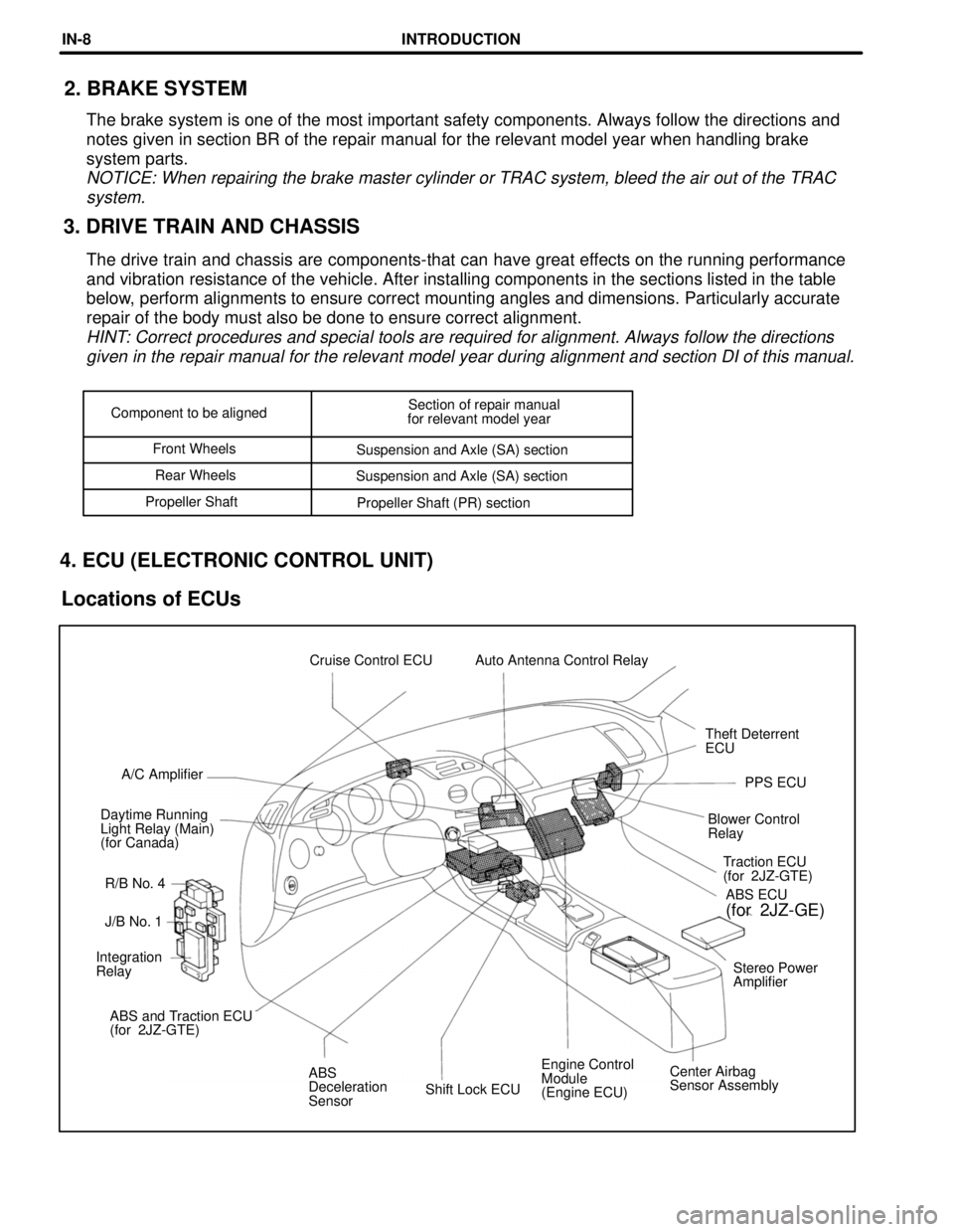
Shift Lock ECUEngine Control
Module
(Engine ECU)Center Airbag
Sensor Assembly ABS
Deceleration
Sensor ABS and Traction ECU
(for 2JZ-GTE)Stereo Power
Amplifier Integration
RelayJ/B No. 1Traction ECU
(for 2JZ-GTE)
R/B No. 4 Daytime Running
Light Relay (Main)
(for Canada)Blower Control
RelayPPS ECU A/C AmplifierTheft Deterrent
ECU Cruise Control ECU Auto Antenna Control Relay
ABS ECU
(for 2JZ-GE)
Component to be alignedSection of repair manual
for relevant model year
Front Wheels
Suspension and Axle (SA) section
Rear Wheels
Suspension and Axle (SA) section
Propeller Shaft
Propeller Shaft (PR) section
3. DRIVE TRAIN AND CHASSIS2. BRAKE SYSTEM
The brake system is one of the most important safety components. Always follow the directions and
notes given in section BR of the repair manual for the relevant model year when handling brake
system parts.
NOTICE: When repairing the brake master cylinder or TRAC system, bleed the air out of the TRAC
system.
The drive train and chassis are components-that can have great effects on the running performance
and vibration resistance of the vehicle. After installing components in the sections listed in the table
below, perform alignments to ensure correct mounting angles and dimensions. Particularly accurate
repair of the body must also be done to ensure correct alignment.
HINT: Correct procedures and special tools are required for alignment. Always follow the directions
given in the repair manual for the relevant model year during alignment and section DI of this manual.
4. ECU (ELECTRONIC CONTROL UNIT)
Locations of ECUs
INTRODUCTIONIN-8