Page 136 of 1807
AC0QQ-01
I03525
N08724
N08893
No. 5 Air Hose
- AIR CONDITIONINGCONDENSER
AC-43
2191 Author�: Date�:
1997 SUPRA (RM502U)
REMOVAL
1. DISCHARGE REFRIGERANT FROM REFRIGERATION
SYSTEM
HINT:
At the time of installation, please refer to the following item.
Evacuate air from refrigeration system.
Charge system with refrigerant and inspect for leakage of refrig-
erant.
Specified amount: 700 ± 50 g (24.96 ± 1.76 oz.)
2. REMOVE BATTERY
3. REMOVE AIR CLEANER DUCT
Remove the bolt and the air cleaner duct.
4. REMOVE AIR CLEANER
(a) Remove the air cleaner cover.
(b) Remove the air cleaner hose.
(c) 2JZ-GTE Engine Models:
Remove the No.1 air hose.
(d) Remove the 3 bolts and screw.
(e) Remove the air cleaner.
5. 2JZ-GTE Engine Models:
REMOVE No.5 AIR HOSE CLAMP
(a) Remove the 2 bolts and clamp.
(b) Remove the air cleaner.
Page 157 of 1807

BODY ELECTRICAL SYSTEM
PRECAUTION
Take care to observe the doing precautions when performing inspection")
BE0DL-01
- BODY ELECTRICALBODY ELECTRICAL SYSTEM
BE-1
1979 Author�: Date�:
1997 SUPRA (RM502U)
BODY ELECTRICAL SYSTEM
PRECAUTION
Take care to observe the doing precautions when performing inspections or removal and replacement of
body electrical related parts.
1. HEADLIGHT SYSTEM
Halogen bulbs have pressurized gas inside and require special handling. They can burst if scratched or
dropped. Hold a bulb only by its plastic or metal case.
Don't touch the glass part of a bulb with bare hands.
2. SRS (SUPPLEMENTAL RESTRAINT SYSTEM)
The SUPRA is equipped with an SRS (Supplemental Restraint System) such as the driver airbag and front
passenger airbag. Failure to carry out service operation in the correct sequence could cause the SRS to
unexpectedly deploy during servicing, possibly leading to a serious accident. Before servicing (including re-
moval or installation of parts, inspection or replacement), be sure to read the precautionary notices in the
RS section.
3. AUDIO SYSTEM
�If the negative (-) terminal cable is disconnected from the battery, the preset AM, FM 1 and FM 2 sta-
tions stored in memory are erased, so be sure to note the stations and reset them after the battery
terminal is reconnected.
�If the negative (-) terminal cable is disconnected from the battery, the ºANTI-THEFT SYSTEMº will
operate when the cable is reconnected, but the radio, tape player and CD player will not operate. Be
sure to input the correct ID number so that the radio, tape player and CD player can be operated again.
4. MOBILE COMMUNICATION SYSTEM
If the vehicle is equipped with a mobile communication system, refer to precautions in the IN section.
Page 169 of 1807
BE1L3-01
Z09193
Z14750
OFF
ON
N16845
- BODY ELECTRICALIGNITION SWITCH AND KEY UNLOCK WARNING
SWITCHBE-13
1991 Author�: Date�:
1997 SUPRA (RM502U)
INSPECTION
1. INSPECT IGNITION SWITCH CONTINUITY
Switch positionTester connectionSpecified condition
LOCK-No continuity
ACC5 - 7Continuity
ON4 - 5 - 7, 2 - 3Continuity
START4 - 7 - 8, 1 - 2 - 3Continuity
If continuity is not as specified, replace the switch.
2. INSPECT KEY UNLOCK WARNING SWITCH CONTI-
NUITY
ConditionTester connectionSpecified condition
SW OFF
(Key removed)-No continuity
SW ON (Key set)1 - 2Continuity
If continuity is not as specified, replace the switch.
3. Key Unlock Warning System:
INSPECT INTEGRATION RELAY OPERATION
(a) Connect the positive (+) lead from the battery to terminal
1, the negative (-) lead to terminals 5 and 10..
(b) Check the buzzer sounds when the negative (-) lead from
the battery is connected to terminal 6..
If operation is not as specified, replace the relay.
Page 170 of 1807

4. INSPEC")
Z07373
Junction Block Side
Connector ºAº
Wire Harness Side
Connector ºBº BE-14
- BODY ELECTRICALIGNITION SWITCH AND KEY UNLOCK WARNING
SWITCH
1992 Author�: Date�:
1997 SUPRA (RM502U)
4. INSPECT RELAY CIRCUIT
Light Auto Turn Off System:
Remove the relay from junction block and inspect the connec-
tors on the wire harness and junction block side, as shown in
the chart.
Tester connectionConditionSpecified condition
A6 - GroundDriver's door courtesy switch OFFNo continuity
A6 - GroundDriver's door courtesy switch ONContinuity
A10 - GroundConstantContinuity
B1 - GroundLight control switch position OFF or TAILNo continuity
B1 - GroundLight control switch position HEADContinuity
B4 - GroundLight control switch position OFFNo continuity
B4 - GroundLight control switch position TAIL or HEADContinuity
A1 - GroundConstantBattery positive voltage
A7 - GroundIgnition switch position LOCK or ACCNo voltage
A7 - GroundIgnition switch position ONBattery positive voltage
B2 - GroundConstantBattery positive voltage
B3 - GroundConstantBattery positive voltage
If the circuit is as specified, try replacing the relay with a new
one.
If the circuit not as specified, inspect the circuits connected to
other parts.
Page 174 of 1807

6. INSPECT DOOR COURTESY SWITCH CONTINUITY
(See page BE-28")
Z07503
Wire Harness Side
Z09181
34
2 143
12 BE-18
- BODY ELECTRICALHEADLIGHT AND TAILLIGHT SYSTEM
1996 Author�: Date�:
1997 SUPRA (RM502U)
6. INSPECT DOOR COURTESY SWITCH CONTINUITY
(See page BE-28)
7. CANADA models only:
INSPECT D.R.L. MAIN RELAY CIRCUIT
Disconnect the connector from relay and inspect the connector
on wire harness side, as shown.
Tester connectionConditionSpecified condition
5 - GroundHeadlight dimmer switch position Low beam or
high beamNo continuity
5 - GroundHeadlight dimmer switch position FlashContinuity
8 - GroundParking brake switch position OFFNo continuity
8 - GroundParking brake switch position ONContinuity
16 - GroundHeadlight dimmer switch position Low beamNo continuity
16 - GroundHeadlight dimmer switch position Flash or High
beamContinuity
13 - GroundConstantContinuity
18 - GroundConstantContinuity
2 - GroundIgnition switch position LOCK or ACCNo voltage
2 - GroundIgnition switch position ONBattery positive voltage
11 - GroundEngine StopNo voltage
11 - GroundEngine RunningBattery positive voltage
15 - Ground
17 - GroundConstantBattery positive voltage
If the circuit is as specified, try replacing the relay with a new
one.
If the circuit is not as specified, inspect the circuit connected to
other parts.
8. INSPECT D.R.L. NO.2 RELAY CONTINUITY
ConditionTester connectionSpecified condition
Constant3 - 4Continuity
Apply B+ between
terminals 3 and 4.1 - 2Continuity
If continuity is not as specified, replace the relay.
Page 175 of 1807
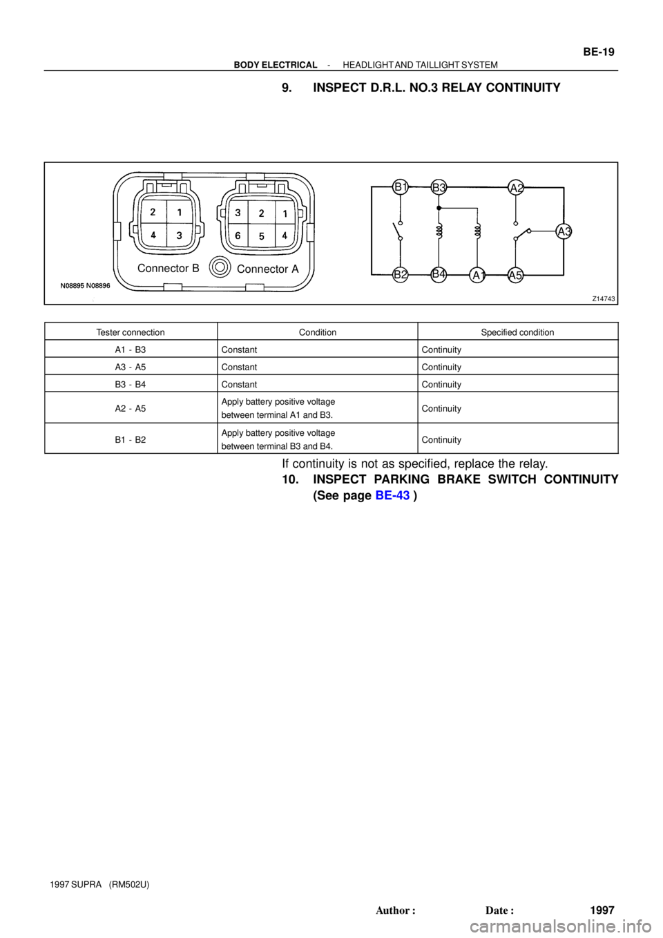
Z14743
Connector B
Connector AB1
B3
B2B4
A1 A5A3 A2
- BODY ELECTRICALHEADLIGHT AND TAILLIGHT SYSTEM
BE-19
1997 Author�: Date�:
1997 SUPRA (RM502U)
9. INSPECT D.R.L. NO.3 RELAY CONTINUITY
Tester connectionConditionSpecified condition
A1 - B3ConstantContinuity
A3 - A5ConstantContinuity
B3 - B4ConstantContinuity
A2 - A5Apply battery positive voltage
between terminal A1 and B3.Continuity
B1 - B2Apply battery positive voltage
between terminal B3 and B4.Continuity
If continuity is not as specified, replace the relay.
10. INSPECT PARKING BRAKE SWITCH CONTINUITY
(See page BE-43)
Page 182 of 1807
13
Z09334
BE-26
- BODY ELECTRICALTURN SIGNAL AND HAZARD WARNING SYSTEM
2004 Author�: Date�:
1997 SUPRA (RM5")
BE0DY-02
Z09367
Right Turn
Left Turn
Connector ºAº
BE1843
2
Turn Signal Light Bulbs (21W)13
Z09334
BE-26
- BODY ELECTRICALTURN SIGNAL AND HAZARD WARNING SYSTEM
2004 Author�: Date�:
1997 SUPRA (RM502U)
INSPECTION
1. INSPECT TURN SIGNAL SWITCH CONTINUITY
Switch positionTester connectionSpecified condition
Left turnA1 - A5Continuity
Neutral-No continuity
Right turnA1 - A8Continuity
If continuity is not as specified, replace the switch.
2. INSPECT TURN SIGNAL FLASHER OPERATION
(a) Connect the terminal 2 to battery positive (+) terminal and
the terminal 3 to battery negative (-) terminal.
(b) Connect the 2 turn signal light bulbs parallel to each other
to terminals 1 and 3, check that the bulbs flash.
HINT:
The turn signal lights should flash between 60 and 120 times
per minute.
3. INSPECT HAZARD WARNING SWITCH CONTINUITY
ConditionTester connectionSpecified condition
Switch OFF7 - 10Continuity
Switch ON7 - 8
4 - 5 - 6 - 9Continuity
Illumination circuit2 - 3Continuity
If continuity is not as specified, replace the switch.
BE3QR-01
Page 185 of 1807
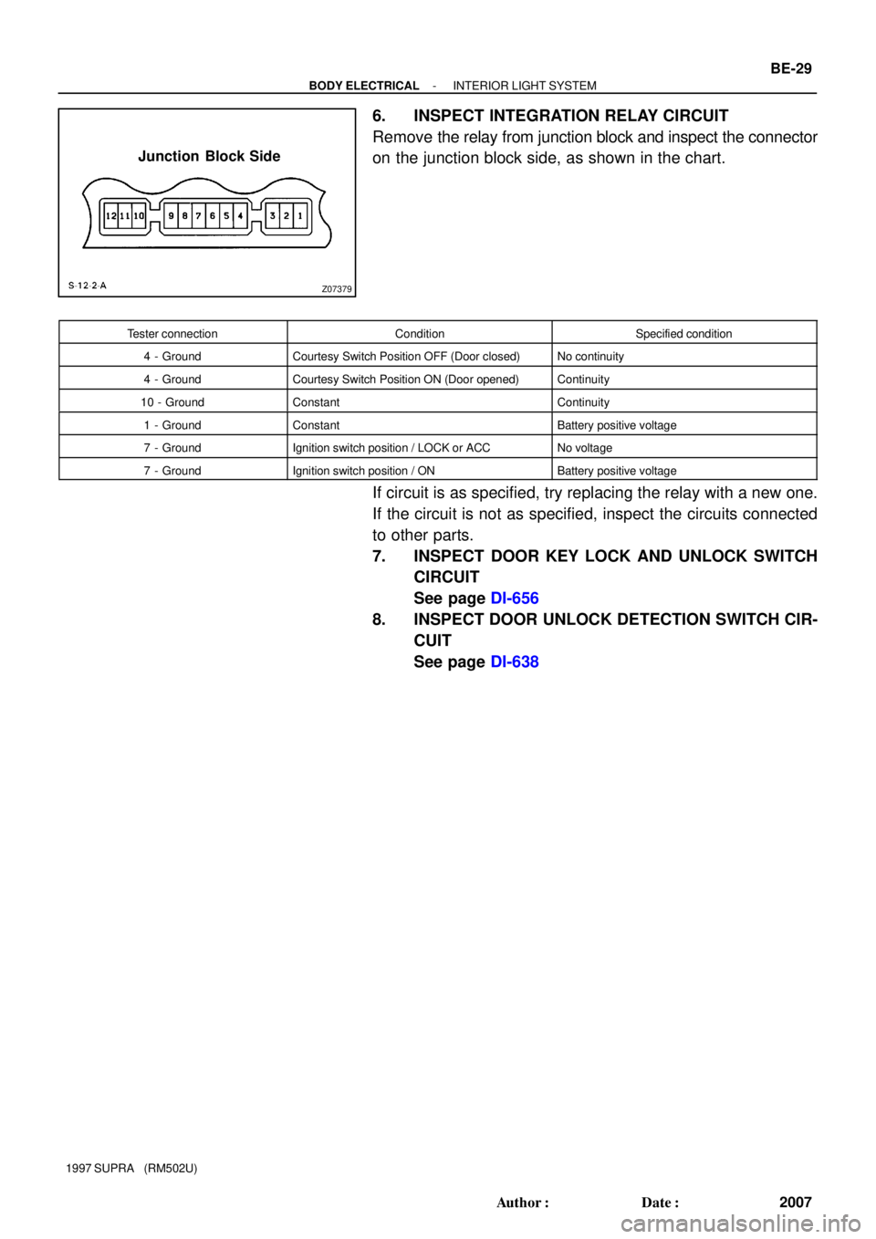
Z07379
Junction Block Side
- BODY ELECTRICALINTERIOR LIGHT SYSTEM
BE-29
2007 Author�: Date�:
1997 SUPRA (RM502U)
6. INSPECT INTEGRATION RELAY CIRCUIT
Remove the relay from junction block and inspect the connector
on the junction block side, as shown in the chart.
Tester connectionConditionSpecified condition
4 - GroundCourtesy Switch Position OFF (Door closed)No continuity
4 - GroundCourtesy Switch Position ON (Door opened)Continuity
10 - GroundConstantContinuity
1 - GroundConstantBattery positive voltage
7 - GroundIgnition switch position / LOCK or ACCNo voltage
7 - GroundIgnition switch position / ONBattery positive voltage
If circuit is as specified, try replacing the relay with a new one.
If the circuit is not as specified, inspect the circuits connected
to other parts.
7. INSPECT DOOR KEY LOCK AND UNLOCK SWITCH
CIRCUIT
See page DI-656
8. INSPECT DOOR UNLOCK DETECTION SWITCH CIR-
CUIT
See page DI-638