Page 460 of 3342
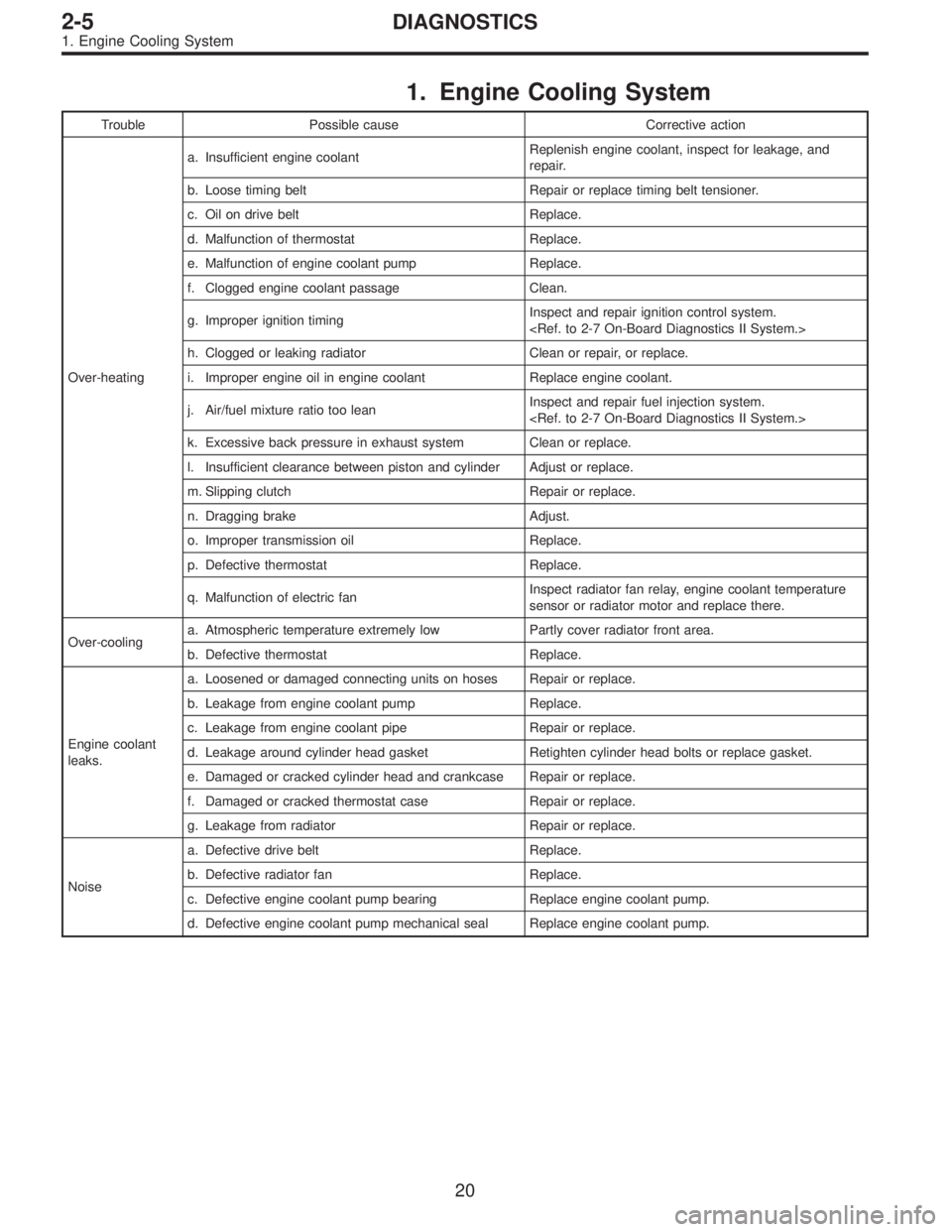
1. Engine Cooling System
Trouble Possible cause Corrective action
Over-heatinga. Insufficient engine coolantReplenish engine coolant, inspect for leakage, and
repair.
b. Loose timing belt Repair or replace timing belt tensioner.
c. Oil on drive belt Replace.
d. Malfunction of thermostat Replace.
e. Malfunction of engine coolant pump Replace.
f. Clogged engine coolant passage Clean.
g. Improper ignition timingInspect and repair ignition control system.
h. Clogged or leaking radiator Clean or repair, or replace.
i. Improper engine oil in engine coolant Replace engine coolant.
j. Air/fuel mixture ratio too leanInspect and repair fuel injection system.
k. Excessive back pressure in exhaust system Clean or replace.
l. Insufficient clearance between piston and cylinder Adjust or replace.
m. Slipping clutch Repair or replace.
n. Dragging brake Adjust.
o. Improper transmission oil Replace.
p. Defective thermostat Replace.
q. Malfunction of electric fanInspect radiator fan relay, engine coolant temperature
sensor or radiator motor and replace there.
Over-coolinga. Atmospheric temperature extremely low Partly cover radiator front area.
b. Defective thermostat Replace.
Engine coolant
leaks.a. Loosened or damaged connecting units on hoses Repair or replace.
b. Leakage from engine coolant pump Replace.
c. Leakage from engine coolant pipe Repair or replace.
d. Leakage around cylinder head gasket Retighten cylinder head bolts or replace gasket.
e. Damaged or cracked cylinder head and crankcase Repair or replace.
f. Damaged or cracked thermostat case Repair or replace.
g. Leakage from radiator Repair or replace.
Noisea. Defective drive belt Replace.
b. Defective radiator fan Replace.
c. Defective engine coolant pump bearing Replace engine coolant pump.
d. Defective engine coolant pump mechanical seal Replace engine coolant pump.
20
2-5DIAGNOSTICS
1. Engine Cooling System
Page 640 of 3342
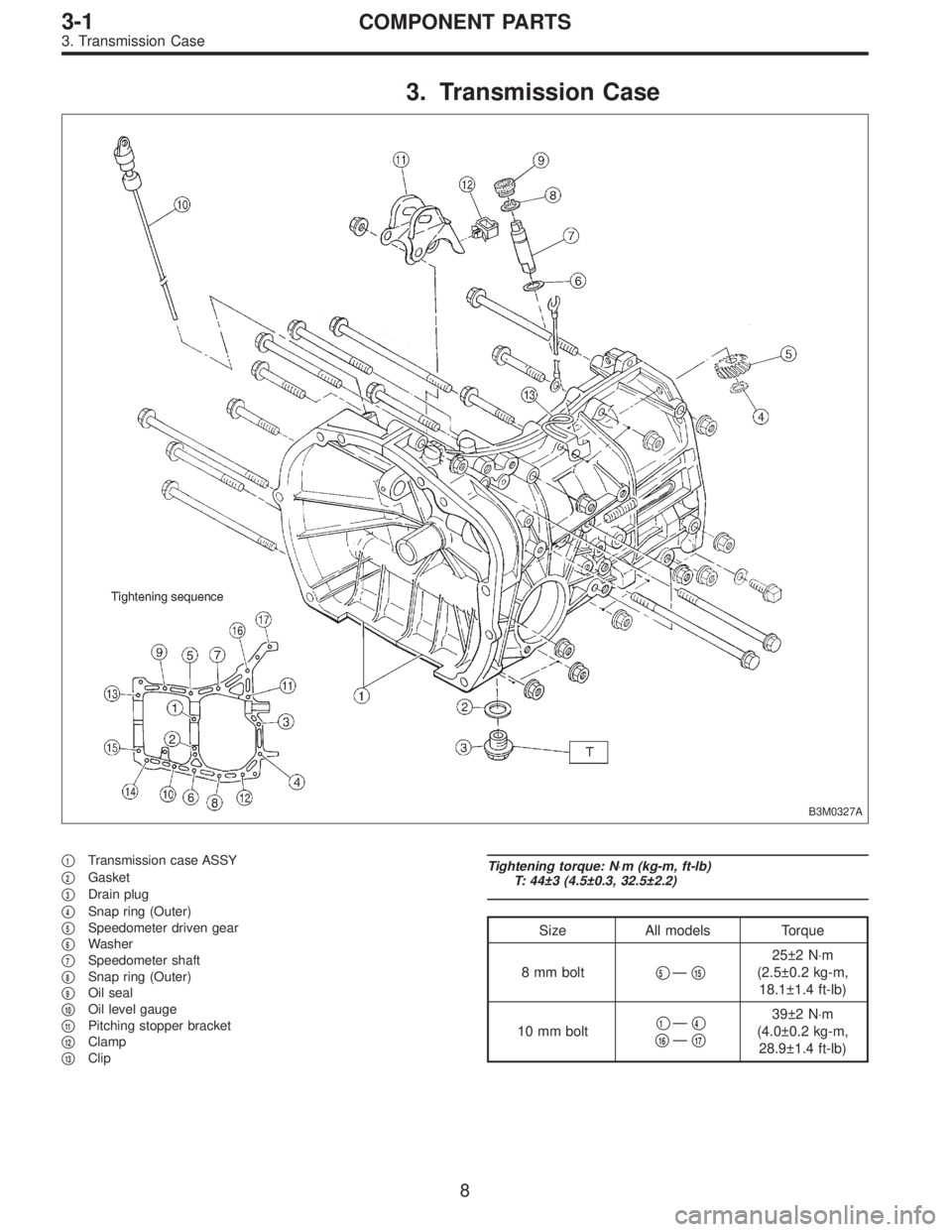
3. Transmission Case
B3M0327A
�1Transmission case ASSY
�
2Gasket
�
3Drain plug
�
4Snap ring (Outer)
�
5Speedometer driven gear
�
6Washer
�
7Speedometer shaft
�
8Snap ring (Outer)
�
9Oil seal
�
10Oil level gauge
�
11Pitching stopper bracket
�
12Clamp
�
13Clip
Tightening torque: N⋅m (kg-m, ft-lb)
T: 44±3 (4.5±0.3, 32.5±2.2)
Size All models Torque
8 mm bolt�
5—�15
25±2 N⋅m
(2.5±0.2 kg-m,
18.1±1.4 ft-lb)
10 mm bolt�
1—�4
�16—�17
39±2 N⋅m
(4.0±0.2 kg-m,
28.9±1.4 ft-lb)
8
3-1COMPONENT PARTS
3. Transmission Case
Page 648 of 3342
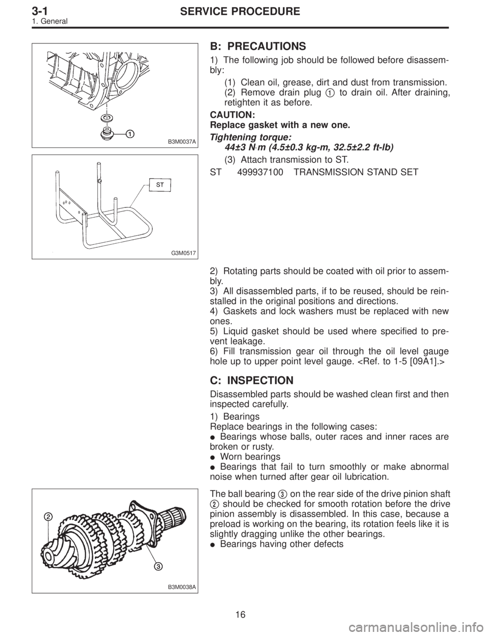
B3M0037A
B: PRECAUTIONS
1) The following job should be followed before disassem-
bly:
(1) Clean oil, grease, dirt and dust from transmission.
(2) Remove drain plug�
1to drain oil. After draining,
retighten it as before.
CAUTION:
Replace gasket with a new one.
Tightening torque:
44±3 N⋅m (4.5±0.3 kg-m, 32.5±2.2 ft-lb)
G3M0517
(3) Attach transmission to ST.
ST 499937100 TRANSMISSION STAND SET
2) Rotating parts should be coated with oil prior to assem-
bly.
3) All disassembled parts, if to be reused, should be rein-
stalled in the original positions and directions.
4) Gaskets and lock washers must be replaced with new
ones.
5) Liquid gasket should be used where specified to pre-
vent leakage.
6) Fill transmission gear oil through the oil level gauge
hole up to upper point level gauge.
C: INSPECTION
Disassembled parts should be washed clean first and then
inspected carefully.
1) Bearings
Replace bearings in the following cases:
�Bearings whose balls, outer races and inner races are
broken or rusty.
�Worn bearings
�Bearings that fail to turn smoothly or make abnormal
noise when turned after gear oil lubrication.
B3M0038A
The ball bearing�3on the rear side of the drive pinion shaft
�
2should be checked for smooth rotation before the drive
pinion assembly is disassembled. In this case, because a
preload is working on the bearing, its rotation feels like it is
slightly dragging unlike the other bearings.
�Bearings having other defects
16
3-1SERVICE PROCEDURE
1. General
Page 670 of 3342
3) Install reverse arm fork spring, ball and interlock
plunger (5.56 x 19.6) to reverse fork rod arm�
5. Insert
reverse fork rod�
6into hole in reverse fork rod arm�5, and
hold it with outer snap ring�
7using ST.
ST 399411700 ACCENT BALL INSTALLER
CAUTION:
Apply grease to plunger to prevent it from falling.
4) Position ball�
8(7.1438), spring�9and gasket�10in
reverse shifter rod hole, on left side transmission case, and
tighten checking ball plug�
11.
CAUTION:
Replace gasket with a new one.
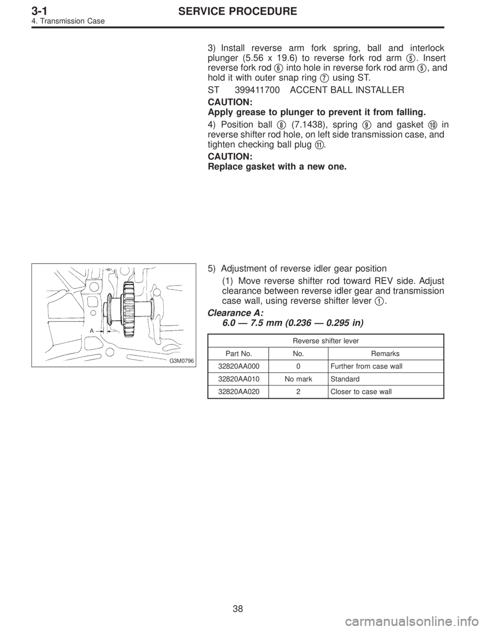
G3M0796
5) Adjustment of reverse idler gear position
(1) Move reverse shifter rod toward REV side. Adjust
clearance between reverse idler gear and transmission
case wall, using reverse shifter lever�
1.
Clearance A:
6.0—7.5 mm (0.236—0.295 in)
Reverse shifter lever
Part No. No. Remarks
32820AA000 0 Further from case wall
32820AA010 No mark Standard
32820AA020 2 Closer to case wall
38
3-1SERVICE PROCEDURE
4. Transmission Case
Page 672 of 3342
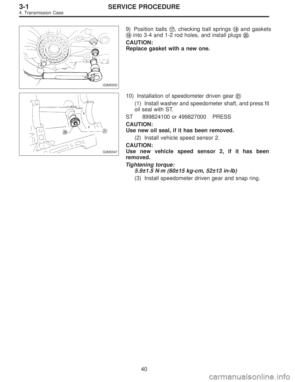
G3M0552
9) Position balls�17, checking ball springs�18and gaskets
�
19into 3-4 and 1-2 rod holes, and install plugs�20.
CAUTION:
Replace gasket with a new one.
G3M0547
10) Installation of speedometer driven gear�21
(1) Install washer and speedometer shaft, and press fit
oil seal with ST.
ST 899824100 or 499827000 PRESS
CAUTION:
Use new oil seal, if it has been removed.
(2) Install vehicle speed sensor 2.
CAUTION:
Use new vehicle speed sensor 2, if it has been
removed.
Tightening torque:
5.9±1.5 N⋅m (60±15 kg-cm, 52±13 in-lb)
(3) Install speedometer driven gear and snap ring.
40
3-1SERVICE PROCEDURE
4. Transmission Case
Page 677 of 3342
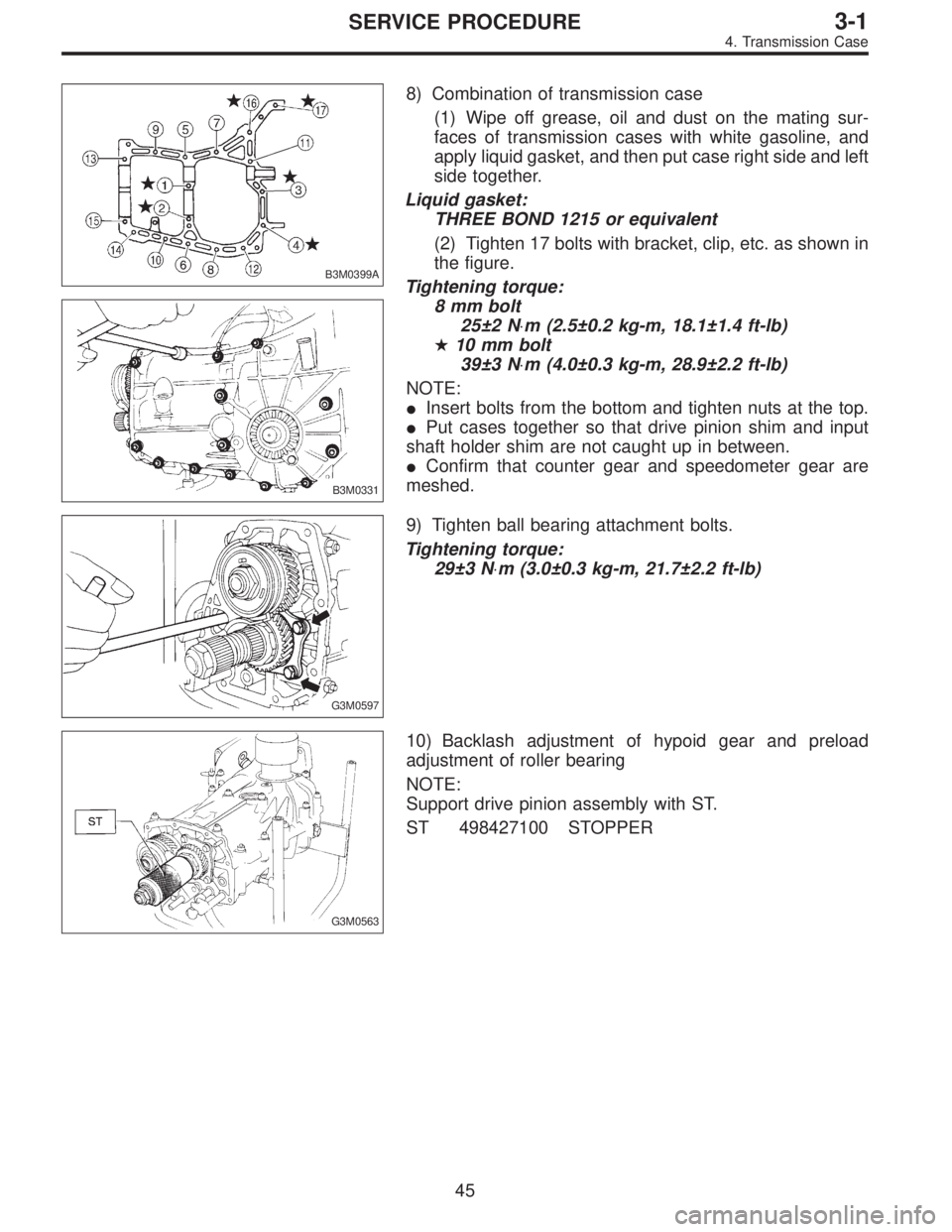
B3M0399A
B3M0331
8) Combination of transmission case
(1) Wipe off grease, oil and dust on the mating sur-
faces of transmission cases with white gasoline, and
apply liquid gasket, and then put case right side and left
side together.
Liquid gasket:
THREE BOND 1215 or equivalent
(2) Tighten 17 bolts with bracket, clip, etc. as shown in
the figure.
Tightening torque:
8 mm bolt
25±2 N⋅m (2.5±0.2 kg-m, 18.1±1.4 ft-lb)
�10 mm bolt
39±3 N⋅m (4.0±0.3 kg-m, 28.9±2.2 ft-lb)
NOTE:
�Insert bolts from the bottom and tighten nuts at the top.
�Put cases together so that drive pinion shim and input
shaft holder shim are not caught up in between.
�Confirm that counter gear and speedometer gear are
meshed.
G3M0597
9) Tighten ball bearing attachment bolts.
Tightening torque:
29±3 N⋅m (3.0±0.3 kg-m, 21.7±2.2 ft-lb)
G3M0563
10) Backlash adjustment of hypoid gear and preload
adjustment of roller bearing
NOTE:
Support drive pinion assembly with ST.
ST 498427100 STOPPER
45
3-1SERVICE PROCEDURE
4. Transmission Case
Page 719 of 3342
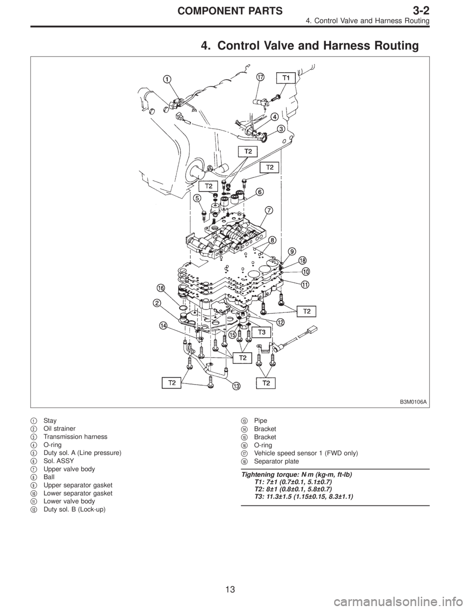
4. Control Valve and Harness Routing
B3M0106A
�1Stay
�
2Oil strainer
�
3Transmission harness
�
4O-ring
�
5Duty sol. A (Line pressure)
�
6Sol. ASSY
�
7Upper valve body
�
8Ball
�
9Upper separator gasket
�
10Lower separator gasket
�
11Lower valve body
�
12Duty sol. B (Lock-up)�
13Pipe
�
14Bracket
�
15Bracket
�
16O-ring
�
17Vehicle speed sensor 1 (FWD only)
�
18Separator plate
Tightening torque: N⋅m (kg-m, ft-lb)
T1: 7±1 (0.7±0.1, 5.1±0.7)
T2: 8±1 (0.8±0.1, 5.8±0.7)
T3: 11.3±1.5 (1.15±0.15, 8.3±1.1)
13
3-2COMPONENT PARTS
4. Control Valve and Harness Routing
Page 721 of 3342
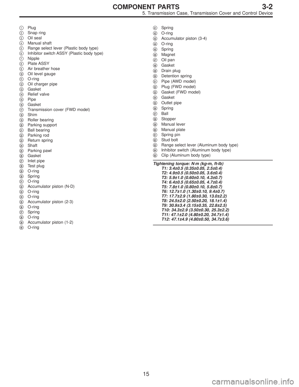
�1Plug
�
2Snap ring
�
3Oil seal
�
4Manual shaft
�
5Range select lever (Plastic body type)
�
6Inhibitor switch ASSY (Plastic body type)
�
7Nipple
�
8Plate ASSY
�
9Air breather hose
�
10Oil level gauge
�
11O-ring
�
12Oil charger pipe
�
13Gasket
�
14Relief valve
�
15Pipe
�
16Gasket
�
17Transmission cover (FWD model)
�
18Shim
�
19Roller bearing
�
20Parking support
�
21Ball bearing
�
22Parking rod
�
23Return spring
�
24Shaft
�
25Parking pawl
�
26Gasket
�
27Inlet pipe
�
28Test plug
�
29O-ring
�
30Spring
�
31O-ring
�
32Accumulator piston (N-D)
�
33O-ring
�
34O-ring
�
35Accumulator piston (2-3)
�
36O-ring
�
37Spring
�
38O-ring
�
39Accumulator piston (1-2)
�
40O-ring�
41Spring
�
42O-ring
�
43Accumulator piston (3-4)
�
44O-ring
�
45Spring
�
46Magnet
�
47Oil pan
�
48Gasket
�
49Drain plug
�
50Detention spring
�
51Pipe (AWD model)
�
52Plug (FWD model)
�
53Gasket (FWD model)
�
54Gasket
�
55Outlet pipe
�
56Spring
�
57Ball
�
58Stopper
�
59Manual lever
�
60Manual plate
�
61Spring pin
�
62Stud bolt
�
63Range select lever (Aluminum body type)
�
64Inhibitor switch (Aluminum body type)
�
65Clip (Aluminum body type)
Tightening torque: N⋅m (kg-m, ft-lb)
T1: 3.4±0.5 (0.35±0.05, 2.5±0.4)
T2: 4.9±0.5 (0.50±0.05, 3.6±0.4)
T3: 5.9±1.0 (0.60±0.10, 4.3±0.7)
T4: 6.4±0.5 (0.65±0.05, 4.7±0.4)
T5: 7.8±1.0 (0.80±0.10, 5.8±0.7)
T6: 12.7±1.0 (1.30±0.10, 9.4±0.7)
T7: 17.7±2.9 (1.80±0.30, 13.0±2.2)
T8: 24.5±2.0 (2.50±0.20, 18.1±1.4)
T9: 30.9±3.4 (3.15±0.35, 22.8±2.5)
T10: 34.3±2.9 (3.50±0.30, 25.3±2.2)
T11: 47.1±2.0 (4.80±0.20, 34.7±1.4)
T12: 47.1±4.9 (4.80±0.50, 34.7±3.6)
15
3-2COMPONENT PARTS
5. Transmission Case, Transmission Cover and Control Device