Page 422 of 3342
1. Lubrication System
A: SPECIFICATIONS
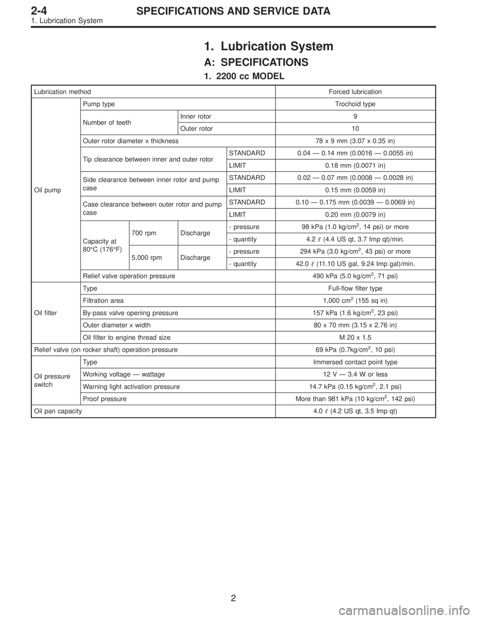
1. 2200 cc MODEL
Lubrication methodForced lubrication
Oil pumpPump typeTrochoid type
Number of teethInner rotor 9
Outer rotor 10
Outer rotor diameter x thickness 78x9mm(3.07 x 0.35 in)
Tip clearance between inner and outer rotorSTANDARD 0.04 — 0.14 mm (0.0016 — 0.0055 in)
LIMIT 0.18 mm (0.0071 in)
Side clearance between inner rotor and pump
caseSTANDARD 0.02 — 0.07 mm (0.0008 — 0.0028 in)
LIMIT 0.15 mm (0.0059 in)
Case clearance between outer rotor and pump
caseSTANDARD 0.10 — 0.175 mm (0.0039 — 0.0069 in)
LIMIT 0.20 mm (0.0079 in)
Capacity at
80°C (176°F)700 rpm Discharge- pressure 98 kPa (1.0 kg/cm
2, 14 psi) or more
- quantity 4.2�(4.4 US qt, 3.7 Imp qt)/min.
5,000 rpm Discharge- pressure 294 kPa (3.0 kg/cm
2, 43 psi) or more
- quantity 42.0�(11.10 US gal, 9.24 Imp gal)/min.
Relief valve operation pressure 490 kPa (5.0 kg/cm
2, 71 psi)
Oil filterTypeFull-flow filter type
Filtration area 1,000 cm
2(155 sq in)
By-pass valve opening pressure 157 kPa (1.6 kg/cm
2, 23 psi)
Outer diameter x width 80 x 70 mm (3.15 x 2.76 in)
Oil filter to engine thread size M 20 x 1.5
Relief valve (on rocker shaft) operation pressure 69 kPa (0.7kg/cm
2, 10 psi)
Oil pressure
switchTypeImmersed contact point type
Working voltage — wattage 12 V — 3.4 W or less
Warning light activation pressure 14.7 kPa (0.15 kg/cm
2, 2.1 psi)
Proof pressure More than 981 kPa (10 kg/cm
2, 142 psi)
Oil pan capacity4.0�(4.2 US qt, 3.5 Imp qt)
2
2-4SPECIFICATIONS AND SERVICE DATA
1. Lubrication System
Page 423 of 3342
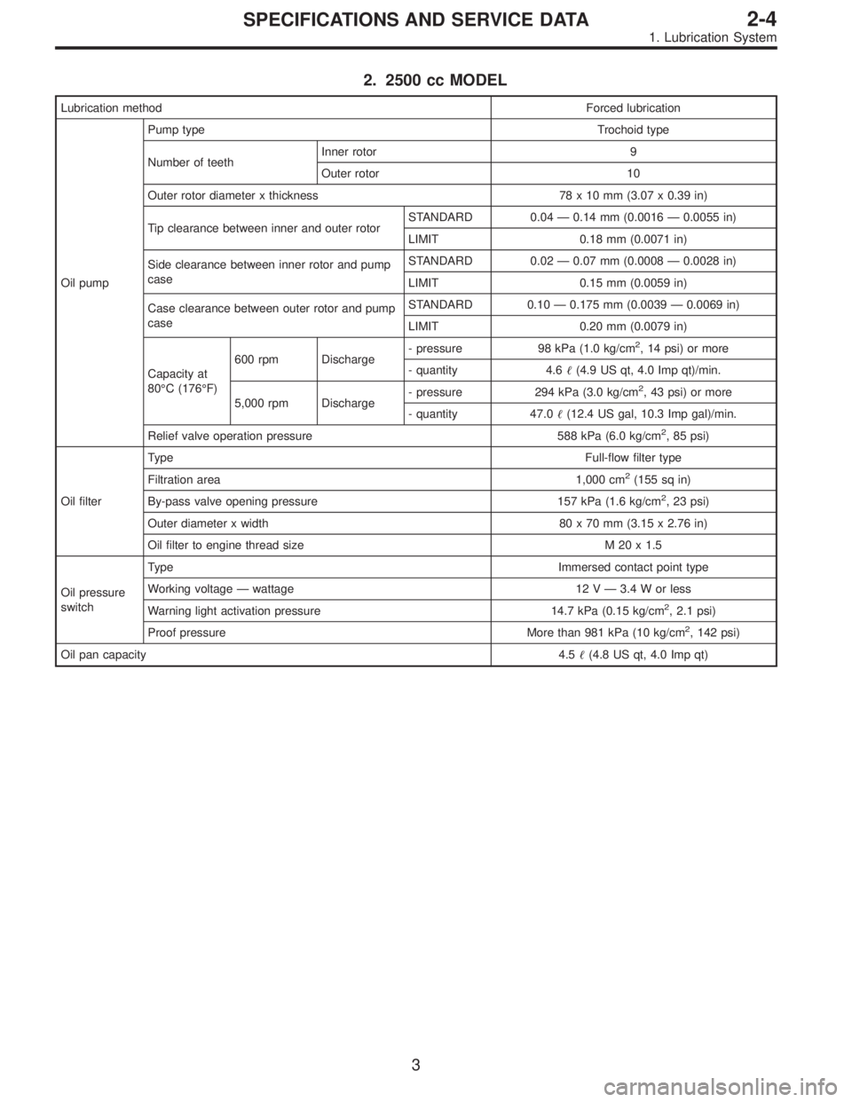
2. 2500 cc MODEL
Lubrication methodForced lubrication
Oil pumpPump typeTrochoid type
Number of teethInner rotor 9
Outer rotor 10
Outer rotor diameter x thickness 78 x 10 mm (3.07 x 0.39 in)
Tip clearance between inner and outer rotorSTANDARD 0.04—0.14 mm (0.0016—0.0055 in)
LIMIT 0.18 mm (0.0071 in)
Side clearance between inner rotor and pump
caseSTANDARD 0.02—0.07 mm (0.0008—0.0028 in)
LIMIT 0.15 mm (0.0059 in)
Case clearance between outer rotor and pump
caseSTANDARD 0.10—0.175 mm (0.0039—0.0069 in)
LIMIT 0.20 mm (0.0079 in)
Capacity at
80°C (176°F)600 rpm Discharge- pressure 98 kPa (1.0 kg/cm
2, 14 psi) or more
- quantity 4.6�(4.9 US qt, 4.0 Imp qt)/min.
5,000 rpm Discharge- pressure 294 kPa (3.0 kg/cm
2, 43 psi) or more
- quantity 47.0�(12.4 US gal, 10.3 Imp gal)/min.
Relief valve operation pressure 588 kPa (6.0 kg/cm
2, 85 psi)
Oil filterTypeFull-flow filter type
Filtration area 1,000 cm
2(155 sq in)
By-pass valve opening pressure 157 kPa (1.6 kg/cm
2, 23 psi)
Outer diameter x width 80 x 70 mm (3.15 x 2.76 in)
Oil filter to engine thread size M 20 x 1.5
Oil pressure
switchTypeImmersed contact point type
Working voltage—wattage 12 V—3.4 W or less
Warning light activation pressure 14.7 kPa (0.15 kg/cm
2, 2.1 psi)
Proof pressure More than 981 kPa (10 kg/cm
2, 142 psi)
Oil pan capacity4.5�(4.8 US qt, 4.0 Imp qt)
3
2-4SPECIFICATIONS AND SERVICE DATA
1. Lubrication System
Page 1141 of 3342
G4M0238
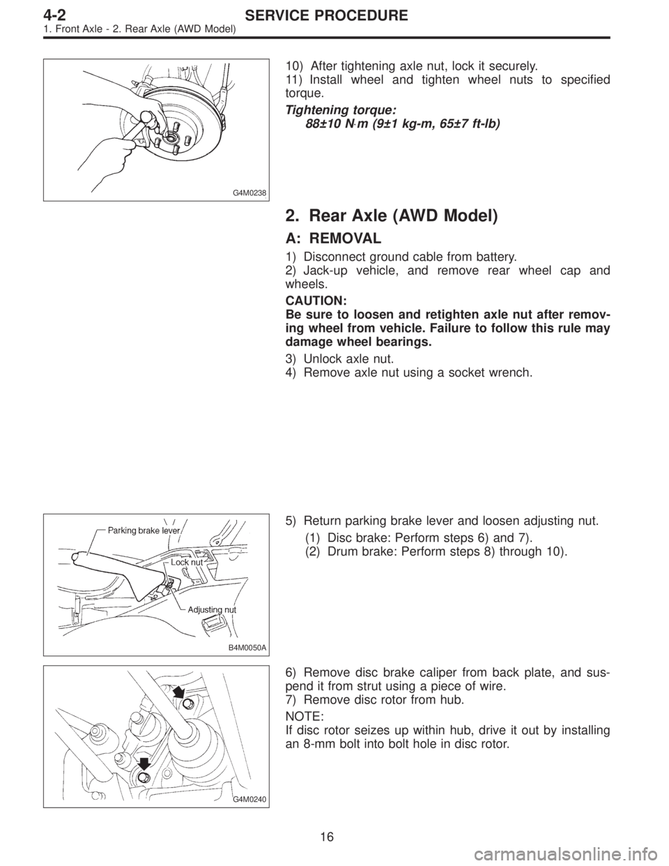
10) After tightening axle nut, lock it securely.
11) Install wheel and tighten wheel nuts to specified
torque.
Tightening torque:
88±10 N⋅m (9±1 kg-m, 65±7 ft-lb)
2. Rear Axle (AWD Model)
A: REMOVAL
1) Disconnect ground cable from battery.
2) Jack-up vehicle, and remove rear wheel cap and
wheels.
CAUTION:
Be sure to loosen and retighten axle nut after remov-
ing wheel from vehicle. Failure to follow this rule may
damage wheel bearings.
3) Unlock axle nut.
4) Remove axle nut using a socket wrench.
B4M0050A
5) Return parking brake lever and loosen adjusting nut.
(1) Disc brake: Perform steps 6) and 7).
(2) Drum brake: Perform steps 8) through 10).
G4M0240
6) Remove disc brake caliper from back plate, and sus-
pend it from strut using a piece of wire.
7) Remove disc rotor from hub.
NOTE:
If disc rotor seizes up within hub, drive it out by installing
an 8-mm bolt into bolt hole in disc rotor.
16
4-2SERVICE PROCEDURE
1. Front Axle - 2. Rear Axle (AWD Model)
Page 1142 of 3342
G4M0238
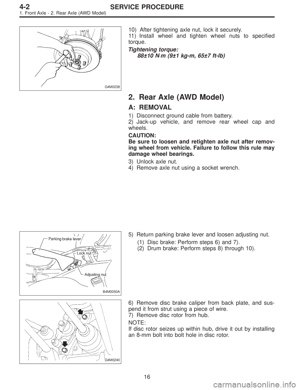
10) After tightening axle nut, lock it securely.
11) Install wheel and tighten wheel nuts to specified
torque.
Tightening torque:
88±10 N⋅m (9±1 kg-m, 65±7 ft-lb)
2. Rear Axle (AWD Model)
A: REMOVAL
1) Disconnect ground cable from battery.
2) Jack-up vehicle, and remove rear wheel cap and
wheels.
CAUTION:
Be sure to loosen and retighten axle nut after remov-
ing wheel from vehicle. Failure to follow this rule may
damage wheel bearings.
3) Unlock axle nut.
4) Remove axle nut using a socket wrench.
B4M0050A
5) Return parking brake lever and loosen adjusting nut.
(1) Disc brake: Perform steps 6) and 7).
(2) Drum brake: Perform steps 8) through 10).
G4M0240
6) Remove disc brake caliper from back plate, and sus-
pend it from strut using a piece of wire.
7) Remove disc rotor from hub.
NOTE:
If disc rotor seizes up within hub, drive it out by installing
an 8-mm bolt into bolt hole in disc rotor.
16
4-2SERVICE PROCEDURE
1. Front Axle - 2. Rear Axle (AWD Model)