Page 574 of 3342
 While pushing release lever�
3to pivot and twisting it to
both sides, fit retainer spring�
5onto the constricted portion
of pivot.
NOTE:
Confirm that retaine")
B2M0633A
1. MECHANICAL APPLICATION TYPE
1) While pushing release lever�
3to pivot and twisting it to
both sides, fit retainer spring�
5onto the constricted portion
of pivot.
NOTE:
Confirm that retainer spring is securely fitted by observing
it through the main case hole.
2) Install release bearing�
6and fasten it with two clips�2.
3) Install release lever seal�
4.
G2M0235
4) After remounting engine and transmission on body,
make adjustment of the clutch release lever end play.
CAUTION:
Take care not to twist the cable during adjustment.
5) Install release lever return spring (Models without hill
holder only).
NOTE:
Hook up the return spring to right side hole of the release
lever.
B2M1257C
2. HYDRAULIC APPLICATION TYPE
1) While pushing release lever�
1to pivot and twisting it to
both sides, fit retainer spring�
2onto the constricted portion
of pivot.
NOTE:
�Apply grease (SUNLIGHT 2: P/N 003602010) to contact
point of release lever and operating cylinder.
�Confirm that retainer spring is securely fitted by observ-
ing it through the main case hole.
2) Install release bearing�
3and fasten it with two clips�4.
3) Install release lever seal�
5.
4) Install operating cylinder�
6.
Tightening torque:
T: 37±3 N⋅m (3.8±0.3 kg-m, 27.5±2.2 ft-lb)
11
2-10SERVICE PROCEDURE
3. Release Bearing and Lever
Page 581 of 3342
B2M1179C
4) Installation is in the reverse order of removal.
NOTE:
Before installing operating cylinder, apply grease (SUN-
LIGHT 2: P/N 003602010) to contact point of release lever
and operating cylinder.
Tightening torque:
T1: 18±3 N⋅m (1.8±0.3 kg-m, 13.0±2.2 ft-lb)
T2: 37±3 N⋅m (3.8±0.3 kg-m, 27.5±2.2 ft-lb)
5) After bleeding air from operating cylinder, ensure that
clutch operates properly.
G2M0979
6. Master Cylinder and Reservoir Tank
A: REMOVAL
1) Remove snap pin�2, clevis pin�1and separate push
rod�
3of master cylinder from clutch pedal.
B2M1260A
2) Remove clutch hose from master cylinder.
CAUTION:
Plug up hose connection to prevent clutch fluid from
spilling out.
B2M1261A
3) Remove master cylinder with reservoir tank.
16
2-10SERVICE PROCEDURE
5. Operating Cylinder - 6. Master Cylinder and Reservoir Tank
Page 582 of 3342
B2M1179C
4) Installation is in the reverse order of removal.
NOTE:
Before installing operating cylinder, apply grease (SUN-
LIGHT 2: P/N 003602010) to contact point of release lever
and operating cylinder.
Tightening torque:
T1: 18±3 N⋅m (1.8±0.3 kg-m, 13.0±2.2 ft-lb)
T2: 37±3 N⋅m (3.8±0.3 kg-m, 27.5±2.2 ft-lb)
5) After bleeding air from operating cylinder, ensure that
clutch operates properly.
G2M0979
6. Master Cylinder and Reservoir Tank
A: REMOVAL
1) Remove snap pin�2, clevis pin�1and separate push
rod�
3of master cylinder from clutch pedal.
B2M1260A
2) Remove clutch hose from master cylinder.
CAUTION:
Plug up hose connection to prevent clutch fluid from
spilling out.
B2M1261A
3) Remove master cylinder with reservoir tank.
16
2-10SERVICE PROCEDURE
5. Operating Cylinder - 6. Master Cylinder and Reservoir Tank
Page 708 of 3342

1. Automatic Transmission and
Differential
A: SPECIFICATIONS
Torque
converter
clutchType Symmetric, 3 element, single stage, 2 phase torque converter clutch coupling
Stall torque ratio2200 cc 2.1 — 2.3
2500 cc 1.8 — 2.0
OUTBACK 2.2 — 2.4
Nominal diameter2200 cc 236 mm (9.29 in)
2500 cc 246 mm (9.69 in)
Stall speed (at sea level)2200 cc 2,200 — 2,600 rpm
2500 cc 2,200 — 2,600 rpm
OUTBACK 2,300 — 2,700 rpm
One-way clutch Sprague type one-way clutch
Automatic
transmissionTransmissionType 4-forward, 1-reverse, double-row planetary gears
Control elementMulti-plate clutch 4 sets
Multi-plate brake 1 set
Band brake 1 set
One-way clutch (sprague type) 2 sets
Gear ratio1st2200 cc 2.785
2500 cc 3.027
2nd2200 cc 1.545
2500 cc 1.619
3rd 1.000
4th 0.694
Reverse 2.272
Tooth number of
planetary gearFront sun gear 33
Front pinion 21
Front internal gear 75
Rear sun gear2200 cc 42
2500 cc 37
Rear pinion2200 cc 17
2500 cc 19
Rear internal gear 75
Clutch number of reverse
clutchDrive plate & driven plate 2
Clutch number of
high clutchDrive plate & driven plate2200 cc ... 4
2500 cc ... 5
Clutch number of forward
clutchDrive plate & driven plate 5
Clutch number of
overrunning clutchDrive plate & driven plate 3
Clutch number of low &
reverse brakeDrive plate & driven plateExcept OUTBACK ... 5
OUTBACK ... 6
Selector positionP (Park)Transmission in neutral, output member
immovable, and engine start possible
R (Reverse) Transmission in reverse for backing
N (Neutral) Transmission in neutral, and engine start possible
D (Drive) Automatic gear change 1st
+
,2nd+
,3rd+
,4th
3 (3rd) Automatic gear change 1st+
,2nd+
,3rd+4th
2 (2nd)2nd gear locked
(Deceleration possible 4th,3rd,2nd)
1 (1st)1st gear locked
(Deceleration possible 4th,3rd,2nd,1st)
Control method Hydraulic remote control
2
3-2SPECIFICATIONS AND SERVICE DATA
1. Automatic Transmission and Differential
Page 713 of 3342

No. Part Name Part Number Inside diameter Outside diameter Dimension Application
AThrust needle
bearing806530020 30 (1.18) 47 (1.85) 3.3 (0.130)A place of high
clutch
BThrust needle
bear")
Unit: mm (in)
No. Part Name Part Number Inside diameter Outside diameter Dimension Application
AThrust needle
bearing806530020 30 (1.18) 47 (1.85) 3.3 (0.130)A place of high
clutch
BThrust needle
bearing806537010 38 (1.50) 53 (2.09) 3.2 (0.126)A place of high
clutch hub
CThrust needle
bearing806537010 38 (1.50) 53 (2.09) 3.2 (0.126)A place of front
sun gear
DThrust needle
bearing806558020 58 (2.28) 78 (3.07) 4.0 (0.157)A place of front
planetary carrier
EThrust needle
bearing806535120 35 (1.38) 53 (2.09) 4.8 (0.189)A place of rear
sun gear
FThrust needle
bearing806534010 34 (1.34) 53 (2.09) 3.37 (0.1327)A place of rear
internal gear
GThrust needle
bearing806558020 58 (2.28) 78 (3.07) 4.0 (0.157)A place of
overrunning clutch
hub
HThrust needle
bearing806542010 42 (1.65) 59 (2.32) 3.6 (0.142)A place of low &
reverse brake
IThrust needle
bearing806536020
806535030
36 (1.42) 53 (2.09)3.8, 4.0, 4.2, 4.4,
4.6, 4.8, 5.0
(0.150, 0.157,
0.165, 0.173,
0.181, 0.189,
0.197)Adjusting end
play of transfer
clutch
∼
806535070
806535090
7
3-2SPECIFICATIONS AND SERVICE DATA
1. Automatic Transmission and Differential
Page 723 of 3342
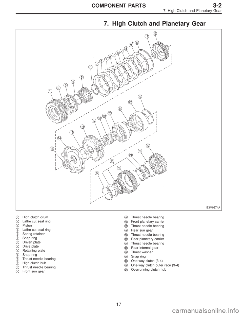
7. High Clutch and Planetary Gear
B3M0374A
�1High clutch drum
�
2Lathe cut seal ring
�
3Piston
�
4Lathe cut seal ring
�
5Spring retainer
�
6Snap ring
�
7Driven plate
�
8Drive plate
�
9Retaining plate
�
10Snap ring
�
11Thrust needle bearing
�
12High clutch hub
�
13Thrust needle bearing
�
14Front sun gear�
15Thrust needle bearing
�
16Front planetary carrier
�
17Thrust needle bearing
�
18Rear sun gear
�
19Thrust needle bearing
�
20Rear planetary carrier
�
21Thrust needle bearing
�
22Rear internal gear
�
23Thrust washer
�
24Snap ring
�
25One-way clutch (3-4)
�
26One-way clutch outer race (3-4)
�
27Overrunning clutch hub
17
3-2COMPONENT PARTS
7. High Clutch and Planetary Gear
Page 760 of 3342
G3M0875
16) Take out the high clutch hub and the thrust bearing.
G3M0876
17) Take out the front sun gear and the thrust bearing.
G3M0877
18) Take out the front planetary carrier and the thrust bear-
ing.
G3M0878
19) Take out the rear planetary carrier, rear sun gear and
the thrust bearing.
G3M0879
20) Take out the rear internal gear and the thrust bearing.
54
3-2SERVICE PROCEDURE
4. Overall Transmission
Page 775 of 3342
G3M0409
13) Install the one-way clutch outer race.
NOTE:
Make sure the forward clutch splines are engaged cor-
rectly.
B3M0117A
14) Assemble the rear internal gear.
(1) Join the thrust needle bearing and thrust washer to
the gear with vaseline, and install the gear while rotat-
ing it.
(2) Securely engage the bearing with the dog of the
overrunning clutch hub.
CAUTION:
Install thrust needle bearing in the correct direction.
NOTE:
Installation is complete when the snap ring top surface of
the forward clutch drum recedes approximately 3.5 mm
(0.138 in).
G3M0890
15) Install the rear planetary carrier.
Attach the thrust needle bearing to the inside of the carrier
with vaseline. Then install the carrier while rotating slowly.
CAUTION:
Install thrust needle bearing in the correct direction.
G3M0891
16) Install the rear sun gear.
NOTE:
Install the gear with the oil groove facing up.
69
3-2SERVICE PROCEDURE
4. Overall Transmission
 Installation is in the reverse order of removal.
NOTE:
Before installing operating cylinder, apply grease (SUN-
LIGHT 2: P/N 003602010) to contact point of release lever
and operating cyli")
 Installation is in the reverse order of removal.
NOTE:
Before installing operating cylinder, apply grease (SUN-
LIGHT 2: P/N 003602010) to contact point of release lever
and operating cyli")
 Take out the high clutch hub and the thrust bearing.
G3M0876
17) Take out the front sun gear and the thrust bearing.
G3M0877
18) Take out the front planetary carrier and the thrust bear-
i")
 Install the one-way clutch outer race.
NOTE:
Make sure the forward clutch splines are engaged cor-
rectly.
B3M0117A
14) Assemble the rear internal gear.
(1) Join the thrust needle bearing")