Page 248 of 3342
 Before checking idle speed, check the following:
(1) Ensure that air cleaner element is free from
clogging, ignition timing is correct, spark plugs are in
good c")
3. Engine Idle Speed
A: MEASUREMENT
1) Before checking idle speed, check the following:
(1) Ensure that air cleaner element is free from
clogging, ignition timing is correct, spark plugs are in
good condition, and that hoses are connected properly.
(2) Ensure that malfunction indicator light (CHECK
ENGINE light) does not illuminate.
2) Warm-up the engine.
G2M0096
3) Connect Subaru Select Monitor or the OBD-II general
scan tool to data link connector.
CAUTION:
When connecting Subaru Select Monitor, turn ignition
switch to OFF.
4) Start the engine and measure engine speed.
NOTE:
Engine speed is indicated on Subaru Select Monitor by
selecting “MODE F04”.
G2M0097
NOTE:
�When using the OBD-II general scan tool, carefully read
its operation manual.
�When Subaru Select Monitor is not used, attach the
pickup sensor on tachometer (Secondary pickup type) to
#1 cylinder spark plug cord.
�This ignition system provides simultaneous ignition for
#1 and #2 plugs. It must be noted that some tachometers
may register twice that of actual engine speed.
5) Check idle speed when unloaded. (With headlights,
heater fan, rear defroster, radiator fan, air conditioning, etc.
OFF)
Idle speed (No load and gears in neutral (MT) or N or
P (AT) position):
700±100 rpm
6) Check idle speed when loaded. (Turn air conditioning
switch to “ON” and operate compressor for at least one
minute before measurement.)
Idle speed [A/C“ON”, no load and gears in neutral
(MT) or N or P (AT) position]:
850±50 rpm
CAUTION:
Never rotate idle adjusting screw. If idle speed is out
of specifications, refer to General On-board Diagnosis
Table under “2-7 On-Board Diagnostics II System”.
3
2-2
3. Engine Idle Speed
Page 1387 of 3342
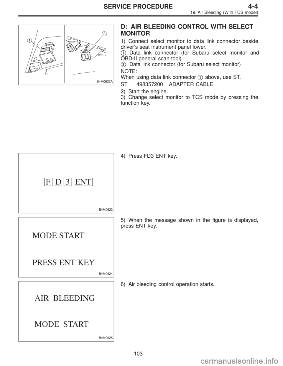
B4M0622A
D: AIR BLEEDING CONTROL WITH SELECT
MONITOR
1) Connect select monitor to data link connector beside
driver’s seat instrument panel lower.
�
1Data link connector (for Subaru select monitor and
OBD-II general scan tool)
�
2Data link connector (for Subaru select monitor)
NOTE:
When using data link connector�
1above, use ST.
ST 498357200 ADAPTER CABLE
2) Start the engine.
3) Change select monitor to TCS mode by pressing the
function key.
B4M0623
4) Press FD3 ENT key.
B4M0624
5) When the message shown in the figure is displayed,
press ENT key.
B4M0625
6) Air bleeding control operation starts.
103
4-4SERVICE PROCEDURE
19. Air Bleeding (With TCS model)
Page 1853 of 3342
 system detects and
indicates a fault in various inputs and outputs of the com-
plex electronic control. CHECK ENGINE malfunction indi-")
1. General
1. GENERAL DESCRIPTION
�The on-board diagnostics (OBD) system detects and
indicates a fault in various inputs and outputs of the com-
plex electronic control. CHECK ENGINE malfunction indi-
cator lamp (MIL) in the combination meter indicates occur-
rence of a fault or trouble.
�Further, against such a failure or sensors as may disable
the drive, the fail-safe function is provided to ensure the
minimal driveability.
�The OBD system incorporated with the vehicles within
this engine family complies with Section 1968.1, California
Code of Regulations (OBD-II regulation). The OBD system
monitors the components and the system malfunction
listed in Engine Section which affects on emissions.
�When the system decides that a malfunction occurs, MIL
illuminates. At the same time of the MIL illumination or
blinking, a diagnostic trouble code (DTC) and a freeze
frame engine conditions are stored into on-board com-
puter.
�The OBD system stores freeze frame engine condition
data (engine load, engine coolant temperature, fuel trim,
engine speed and vehicle speed, etc.) into on-board com-
puter when it detects a malfunction first.
�If the OBD system detects the various malfunctions
including the fault of fuel trim or misfire, the OBD system
first stores freeze frame engine conditions about the fuel
trim or misfire.
�When the malfunction does not occur again for three
consecutive driving cycles, MIL is turned off, but DTC
remains at on-board computer.
�The OBD-II system is capable of communication with a
general scan tool (OBD-II general scan tool) formed by ISO
9141 CARB.
�The OBD-II diagnostics procedure is different from the
usual diagnostics procedure. When troubleshooting OBD-II
vehicles, connect Subaru select monitor or the OBD-II gen-
eral scan tool to the vehicle.
A: ENGINE
1. ENGINE AND EMISSION CONTROL SYSTEM
�The Multipoint Fuel Injection (MFI) system is a system
that supplies the optimum air-fuel mixture to the engine for
all the various operating conditions through the use of the
latest electronic technology.
With this system fuel, which is pressurized at a constant
pressure, is injected into the intake air passage of the cyl-
inder head. The injection quantity of fuel is controlled by an
intermittent injection system where the electro-magnetic
injection valve (fuel injector) opens only for a short period
of time, depending on the quantity of air required for one
cycle of operation. In actual operation, the injection quan-
2
2-7ON-BOARD DIAGNOSTICS II SYSTEM
1. General
Page 1856 of 3342

�
2Ignition coil
�
3Ignitor
�
4Crankshaft position sensor
�
5Camshaft position sensor
�
6Throttle position sensor
�
7Fuel injectors
�
8Pressure regulator
�
9Engine coolan")
�1Engine control module (ECM)
�
2Ignition coil
�
3Ignitor
�
4Crankshaft position sensor
�
5Camshaft position sensor
�
6Throttle position sensor
�
7Fuel injectors
�
8Pressure regulator
�
9Engine coolant temperature sensor
�
10Mass air flow sensor
�
11Idle air control solenoid valve
�
12Purge control solenoid valve
�
13Fuel pump
�
14PCV valve
�
15Air cleaner
�
16Canister
�
17Main relay
�
18Fuel pump relay
�
19Fuel filter
�
20Front catalytic converter
�
21Rear catalytic converter
�
22EGR valve (AT vehicles only)
�
23EGR control solenoid valve (AT vehicles only)
�
24Radiator fan�
25Radiator fan relay
�
26Pressure sources switching solenoid valve
�
27Knock sensor
�
28Back-pressure transducer (AT vehicles only)
�
29Front oxygen sensor
�
30Rear oxygen sensor (2200 cc Federal spec. vehicles)
�
31Pressure sensor
�
32A/C compressor
�
33Inhibitor switch
�
34CHECK ENGINE malfunction indicator lamp (MIL)
�
35Tachometer
�
36A/C relay
�
37A/C control module
�
38Ignition switch
�
39Transmission control module (TCM) (AT vehicles only)
�
40ABS/TCS control module (TCS equipped models)
�
41Vehicle speed sensor
�
42Data link connector (For Subaru select monitor)
�
43Data link connector (For Subaru select monitor and OBD-II
general scan tool)
�
44Two way valve
�
45Rear oxygen sensor (2200 cc California spec. vehicles)
�
46Filter
5
2-7ON-BOARD DIAGNOSTICS II SYSTEM
1. General
Page 1858 of 3342

�
2Ignition coil
�
3Ignitor
�
4Crankshaft position sensor
�
5Camshaft position sensor
�
6Throttle position sensor
�
7Fuel injectors
�
8Pressure regulator
�
9Engine coolan")
�1Engine control module (ECM)
�
2Ignition coil
�
3Ignitor
�
4Crankshaft position sensor
�
5Camshaft position sensor
�
6Throttle position sensor
�
7Fuel injectors
�
8Pressure regulator
�
9Engine coolant temperature sensor
�
10Mass air flow sensor
�
11Idle air control solenoid valve
�
12Purge control solenoid valve
�
13Fuel pump
�
14PCV valve
�
15Air cleaner
�
16Canister
�
17Main relay
�
18Fuel pump relay
�
19Fuel filter
�
20Front catalytic converter
�
21Rear catalytic converter
�
22EGR valve (AT vehicles only)
�
23EGR control solenoid valve (AT vehicles only)
�
24Radiator fan
�
25Radiator fan relay
�
26Pressure sources switching solenoid valve�
27Front oxygen sensor
�
28Rear oxygen sensor (2200 cc Federal spec. vehicles)
�
29Pressure sensor
�
30A/C compressor (With A/C models)
�
31Inhibitor switch
�
32CHECK ENGINE malfunction indicator lamp (MIL)
�
33Tachometer
�
34A/C relay (With A/C models)
�
35A/C control module (With A/C models)
�
36Ignition switch
�
37Transmission control module (TCM)
�
38Vehicle speed sensor
�
39Data link connector (For Subaru select monitor)
�
40Data link connector (For Subaru select monitor and OBD-II
general scan tool)
�
41Rear oxygen sensor (2200 cc California spec. vehicles)
�
42Knock sensor
�
43Back-pressure transducer (AT vehicles only)
�
44Filter
�
45Fuel tank pressure sensor
�
46Pressure control solenoid valve
�
47Fuel temperature sensor
�
48Fuel level sensor
�
49Vent control solenoid valve
�
50Air filter
7
2-7ON-BOARD DIAGNOSTICS II SYSTEM
1. General
Page 1860 of 3342

�
2Ignition coil
�
3Ignitor
�
4Crankshaft position sensor
�
5Camshaft position sensor
�
6Throttle position sensor
�
7Fuel injectors
�
8Pressure regulator
�
9Engine coolan")
�1Engine control module (ECM)
�
2Ignition coil
�
3Ignitor
�
4Crankshaft position sensor
�
5Camshaft position sensor
�
6Throttle position sensor
�
7Fuel injectors
�
8Pressure regulator
�
9Engine coolant temperature sensor
�
10Mass air flow sensor
�
11Idle air control solenoid valve
�
12Purge control solenoid valve
�
13Fuel pump
�
14PCV valve
�
15Air cleaner
�
16Canister
�
17Main relay
�
18Fuel pump relay
�
19Fuel filter
�
20Front catalytic converter
�
21Rear catalytic converter
�
22EGR valve�
23EGR control solenoid valve
�
24Radiator fan
�
25Radiator fan relay
�
26Pressure sources switching solenoid valve
�
27Knock sensor
�
28Back-pressure transducer
�
29Front oxygen sensor
�
30Rear oxygen sensor
�
31Pressure sensor
�
32A/C compressor
�
33Inhibitor switch
�
34CHECK ENGINE malfunction indicator lamp (MIL)
�
35Tachometer
�
36A/C relay
�
37A/C control module
�
38Ignition switch
�
39Transmission control module (TCM)
�
40Vehicle speed sensor
�
41Data link connector (Subaru select monitor)
�
42Data link connector (OBD-II general scan tool)
�
43Two way valve
�
44Filter
9
2-7ON-BOARD DIAGNOSTICS II SYSTEM
1. General
Page 1863 of 3342
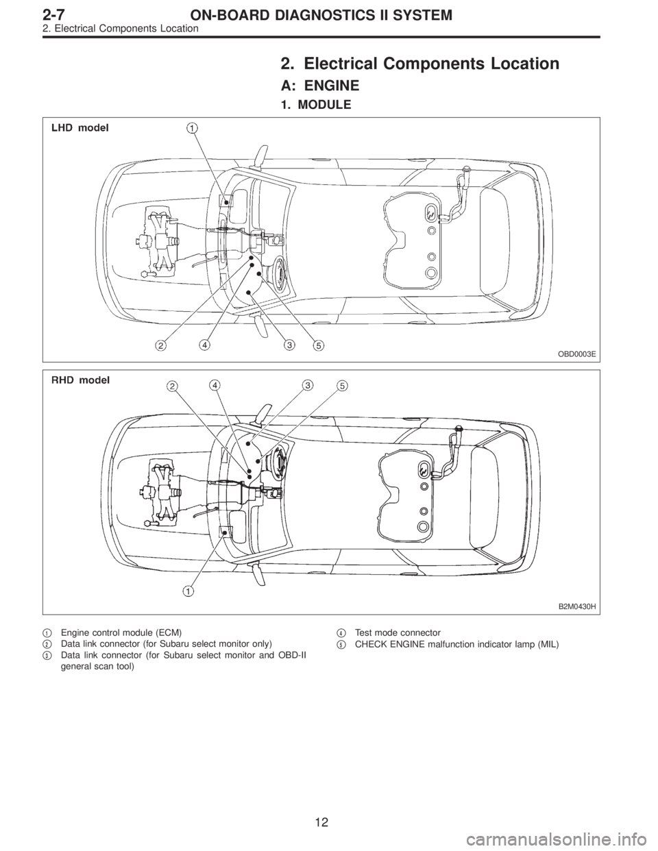
2. Electrical Components Location
A: ENGINE
1. MODULE
OBD0003E
B2M0430H
�1Engine control module (ECM)
�
2Data link connector (for Subaru select monitor only)
�
3Data link connector (for Subaru select monitor and OBD-II
general scan tool)�
4Test mode connector
�
5CHECK ENGINE malfunction indicator lamp (MIL)
12
2-7ON-BOARD DIAGNOSTICS II SYSTEM
2. Electrical Components Location
Page 1864 of 3342
OBD0004BB2M0431B
OBD0005GB2M0432C
OBD0006EB2M0433C
B2M0470A
13
2-7ON-BOARD DIAGNOSTICS II SYSTEM
2. Electrical Components Location