Page 277 of 3342
3. Timing Belt
A: REMOVAL
1. CRANKSHAFT PULLEY AND BELT COVER
G2M0107
G2M0108
1) Remove V-belt and A/C belt tensioner.
2) Remove pulley bolt. To lock crankshaft use ST.
ST 499977000 CRANKSHAFT PULLEY WRENCH
3) Remove crankshaft pulley.
4) Remove left side belt cover.
5) Remove right side belt cover.
6) Remove front belt cover.
15
2-3SERVICE PROCEDURE
3. Timing Belt
Page 278 of 3342
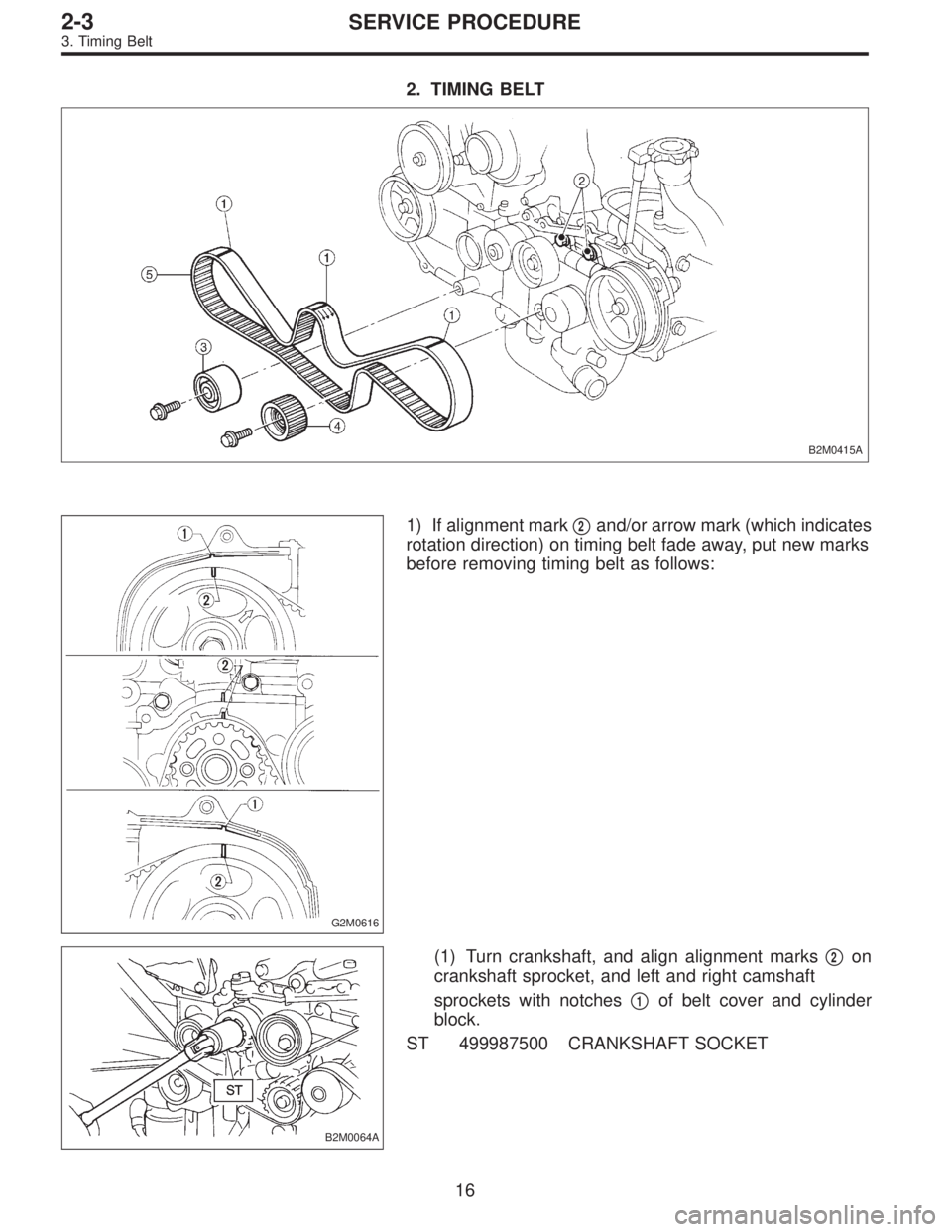
2. TIMING BELT
B2M0415A
G2M0616
1) If alignment mark�2and/or arrow mark (which indicates
rotation direction) on timing belt fade away, put new marks
before removing timing belt as follows:
B2M0064A
(1) Turn crankshaft, and align alignment marks�2on
crankshaft sprocket, and left and right camshaft
sprockets with notches�
1of belt cover and cylinder
block.
ST 499987500 CRANKSHAFT SOCKET
16
2-3SERVICE PROCEDURE
3. Timing Belt
Page 279 of 3342
G2M0111
(2) Using white paint, put alignment and/or arrow
marks on timing belts in relation to the sprockets.
Z
1: 44 tooth length
Z
2: 40.5 tooth length
B2M0065
2) Loosen tensioner adjuster mounting bolts.
3) Remove belt idler.
4) Remove belt idler No. 2.
5) Remove timing belt.
6) Remove tensioner adjuster.
17
2-3SERVICE PROCEDURE
3. Timing Belt
Page 280 of 3342
3. BELT TENSIONER AND IDLER
G2M0112
1) Remove belt idler.
2) Remove belt tensioner and spacer.
3) Remove belt tensioner adjuster.
18
2-3SERVICE PROCEDURE
3. Timing Belt
Page 281 of 3342
4. SPROCKET
B2M0416A
G2M0114
1) Remove left side camshaft sprocket.
2) Remove right side camshaft sprocket. To lock camshaft
use ST.
ST 499207100 CAMSHAFT SPROCKET WRENCH
3) Remove crankshaft sprocket.
4) Remove left side belt cover No. 2.
5) Remove right side belt cover No. 2.
CAUTION:
Do not damage or lose the seal rubber when removing
belt covers.
6) Remove tensioner bracket.
19
2-3SERVICE PROCEDURE
3. Timing Belt
Page 282 of 3342
 Check timing belt teeth for breaks, cracks, and wear. If
any fault is found, replace belt.
2) Check the condition of back side of belt; if any crack is
found, replace b")
B: INSPECTION
1. TIMING BELT
1) Check timing belt teeth for breaks, cracks, and wear. If
any fault is found, replace belt.
2) Check the condition of back side of belt; if any crack is
found, replace belt.
CAUTION:
�Be careful not to let oil, grease or coolant contact
the belt. Remove quickly and thoroughly if this hap-
pens.
G2M0115
�Do not bend the belt sharply.
Bending radius: h
60 mm (2.36 in) or more
2. BELT TENSION ADJUSTER
1) Visually check oil seals for leaks, and rod ends for
abnormal wear or scratches. If necessary, replace belt ten-
sion adjuster.
CAUTION:
Slight traces of oil at rod’s oil seal does not indicate a
problem.
2) While holding tensioner with both hands, push the rod
section against floor or wall ensuring the rod section will
react as follows:
(1) When applying a force of 147 N (15 kg, 33 lb), the
rod section should not sink.
(2) When applying a force of 147 to 490 N (15 to 50 kg,
33 to 110 lb), the rod section should maintain a projec-
tionally acting force and should not sink within 8.5 sec-
onds.
20
2-3SERVICE PROCEDURE
3. Timing Belt
Page 283 of 3342
B2M0108A
3) Measure the extension of rod beyond the body. If it is
not within specifications, replace with a new one.
Rod extension: H
15.4 — 16.4 mm (0.606 — 0.646 in)
3. BELT TENSIONER
1) Check mating surfaces of timing belt and contact point
of tension adjuster rod for abnormal wear or scratches.
Replace belt tensioner if faulty.
2) Check spacer and tensioner bushing for wear.
3) Check tensioner for smooth rotation. Replace if noise or
excessive play is noted.
4) Check tensioner for grease leakage.
4. BELT IDLER
1) Check idler for smooth rotation. Replace if noise or
excessive play is noted.
2) Check outer contacting surfaces of idler pulley for
abnormal wear and scratches.
3) Check idler for grease leakage.
5. SPROCKET
1) Check sprocket teeth for abnormal wear and scratches.
2) Make sure there is no free play between sprocket and
key.
3) Check crankshaft sprocket notch for sensor for damage
and contamination of foreign matter.
21
2-3SERVICE PROCEDURE
3. Timing Belt
Page 284 of 3342
C: INSTALLATION
1. SPROCKET
B2M0416B
Tightening torque: N⋅m (kg-m, ft-lb)
T1: 5±1 (0.5±0.1, 3.6±0.7)
T2: 25±2 (2.5±0.2, 18.1±1.4)
T3: 78±5 (8.0±0.5, 57.9±3.6)
G2M0114
1) Install right side belt cover No. 2.
2) Install tensioner bracket.
3) Install left side belt cover No. 2.
4) Install crankshaft sprocket.
5) Install right side camshaft sprocket and left side cam-
shaft sprocket. To lock camshaft use ST.
ST 499207100 CAMSHAFT SPROCKET WRENCH
CAUTION:
Do not confuse left and right side camshaft sprockets
during installation. The left side camshaft sprocket is
identified by a projection used to monitor cam angle
sensor.
22
2-3SERVICE PROCEDURE
3. Timing Belt
 Remove V-belt and A/C belt tensioner.
2) Remove pulley bolt. To lock crankshaft use ST.
ST 499977000 CRANKSHAFT PULLEY")
 Using white paint, put alignment and/or arrow
marks on timing belts in relation to the sprockets.
Z
1: 44 tooth length
Z
2: 40.5 tooth length
B2M0065
2) Loosen tensioner adjuster mounting")
 Remove belt idler.
2) Remove belt tensioner and spacer.
3) Remove belt tensioner adjuster.
18
2-3SERVICE PROCEDURE
3. Timing Belt")
 Remove left side camshaft sprocket.
2) Remove right side camshaft sprocket. To lock camshaft
use ST.
ST 499207100 CAMSHAFT SPROCKET WRENCH
3) Remove crankshaft sprocket")
 Measure the extension of rod beyond the body. If it is
not within specifications, replace with a new one.
Rod extension: H
15.4 — 16.4 mm (0.606 — 0.646 in)
3. BELT TENSIONER
1) Check")

T1: 5±1 (0.5±0.1, 3.6±0.7)
T2: 25±2 (2.5±0.2, 18.1±1.4)
T3: 78±5 (8.0±0.5, 57.9±3.6)
G2M0114
1) Install right side")