Page 1798 of 3342

B6M0361A
22. Security System
A: REMOVAL AND INSTALLATION
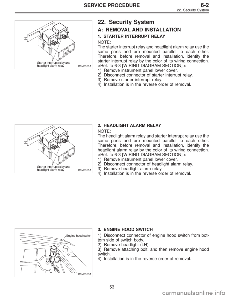
1. STARTER INTERRUPT RELAY
NOTE:
The starter interrupt relay and headlight alarm relay use the
same parts and are mounted parallel to each other.
Therefore, before removal and installation, identify the
starter interrupt relay by the color of its wiring connection.
1) Remove instrument panel lower cover.
2) Disconnect connector of starter interrupt relay.
3) Remove starter interrupt relay.
4) Installation is in the reverse order of removal.
B6M0361A
2. HEADLIGHT ALARM RELAY
NOTE:
The headlight alarm relay and starter interrupt relay use the
same parts and are mounted parallel to each other.
Therefore, before removal and installation, identify the
headlight alarm relay by the color of its wiring connection.
1) Remove instrument panel lower cover.
2) Disconnect connector of headlight alarm relay.
3) Remove headlight alarm relay.
4) Installation is in the reverse order of removal.
B6M0363A
3. ENGINE HOOD SWITCH
1) Disconnect connector of engine hood switch from bot-
tom side of switch body.
2) Remove headlight (LH).
3) Remove attaching bolt, and then remove engine hood
switch.
4) Installation is in the reverse order of removal.
53
6-2SERVICE PROCEDURE
22. Security System
Page 1813 of 3342
2. AT Shift Lock System
A: WIRING DIAGRAM
B6M0466
68
6-2DIAGNOSTICS
2. AT Shift Lock System
Page 1939 of 3342
7. Diagnostics for CHECK ENGINE
Malfunction Indicator Lamp (MIL)
A: CHECK ENGINE MALFUNCTION
INDICATOR LAMP (MIL) DOES NOT COME
ON.
DIAGNOSIS:
�The CHECK ENGINE malfunction indicator lamp (MIL)
circuit is open or shorted.
TROUBLE SYMPTOM:
�When ignition switch is turned ON (engine OFF), MIL
does not come on.
WIRING DIAGRAM:
B2M0507
88
2-7ON-BOARD DIAGNOSTICS II SYSTEM
7. Diagnostics for CHECK ENGINE Malfunction Indicator Lamp (MIL)
Page 1942 of 3342
B: CHECK ENGINE MALFUNCTION
INDICATOR LAMP (MIL) DOES NOT GO OFF.
DIAGNOSIS:
�The CHECK ENGINE malfunction indicator lamp (MIL)
circuit is shorted.
TROUBLE SYMPTOM:
�Although MIL comes on when engine runs, trouble code
is not shown on Subaru select monitor or OBD-II general
scan tool display.
WIRING DIAGRAM:
B2M0507
91
2-7ON-BOARD DIAGNOSTICS II SYSTEM
7. Diagnostics for CHECK ENGINE Malfunction Indicator Lamp (MIL)
Page 1944 of 3342
C: CHECK ENGINE MALFUNCTION
INDICATOR LAMP (MIL) DOES NOT BLINK AT
A CYCLE OF 3 HZ.
DIAGNOSIS:
�The CHECK ENGINE malfunction indicator lamp (MIL)
circuit is open or shorted.
�Test mode connector circuit is in open.
TROUBLE SYMPTOM:
�When inspection mode, MIL does not blink at a cycle of
3 Hz.
WIRING DIAGRAM:
B2M0511
B2M0470C
7C1CHECK OPERATION OF CHECK ENGINE
MALFUNCTION INDICATOR LAMP (MIL).
1) Turn ignition switch to OFF.
2) Disconnect test mode connector.
3) Turn ignition switch to ON.
: Does the MIL come on?
: Go to step7C2.
: Repair the MIL circuit.
93
2-7ON-BOARD DIAGNOSTICS II SYSTEM
7. Diagnostics for CHECK ENGINE Malfunction Indicator Lamp (MIL)
Page 1946 of 3342
D: CHECK ENGINE MALFUNCTION
INDICATOR LAMP (MIL) REMAINS BLINKING
AT A CYCLE OF 3 Hz.
DIAGNOSIS:
�Test mode connector circuit is shorted.
TROUBLE SYMPTOM:
�Even though test mode connector is disconnected, MIL
blinks at a cycle of 3 Hz when ignition switch is turned to
ON.
WIRING DIAGRAM:
B2M0511
B2M0515A
7D1CHECK HARNESS BETWEEN ECM CON-
NECTOR AND ENGINE GROUNDING
TERMINAL.
1) Turn ignition switch to OFF.
2) Disconnect connector from ECM.
3) Measure resistance of harness between ECM connec-
tor and chassis ground.
: Connector & terminal
(B84) No.84—Chassis ground:
Is resistance less than 5Ω?
: Repair short circuit in harness between ECM and
test mode connector.
: Replace ECM.
95
2-7ON-BOARD DIAGNOSTICS II SYSTEM
7. Diagnostics for CHECK ENGINE Malfunction Indicator Lamp (MIL)
Page 1948 of 3342
B: STARTER MOTOR CIRCUIT
WIRING DIAGRAM:
B2M1047
CAUTION:
After repair or replacement of faulty parts, conduct
CLEAR MEMORY and INSPECTION MODES.
OBD0724
8B1CHECK INPUT SIGNAL FOR STARTER
MOTOR.
1) Turn ignition switch to OFF.
2) Disconnect connector from starter motor.
3) Turn ignition switch to ST.
97
2-7ON-BOARD DIAGNOSTICS II SYSTEM
8. Diagnostics for Engine Starting Failure
Page 1954 of 3342
C: CONTROL MODULE POWER SUPPLY AND
GROUND LINE
WIRING DIAGRAM:
B2M1049
CAUTION:
After repair or replacement of faulty parts, conduct
CLEAR MEMORY and INSPECTION MODES.
103
2-7ON-BOARD DIAGNOSTICS II SYSTEM
8. Diagnostics for Engine Starting Failure