Page 2456 of 3342
 Install combination meter.
(2) Connect connectors to TCM and vehicle speed
sensor 2.
(3) Lift-up the vehicle or set the vehicle on free roller.
(4) Turn igni")
OBD0145A
�Using Subaru select monitor:
(1) Install combination meter.
(2) Connect connectors to TCM and vehicle speed
sensor 2.
(3) Lift-up the vehicle or set the vehicle on free roller.
(4) Turn ignition switch to OFF.
(5) Connect the Subaru select monitor to data link con-
nector.
(6) Turn ignition switch to ON and Subaru select moni-
tor switch to ON.
CAUTION:
On AWD models, raise all wheels off floor.
(7) Push the TCS OFF switch to ON. (With TCS mod-
els)
G3M0726
B3M0384
(8) Start the engine, and drive the wheels.
(9) Read data on Subaru select monitor.
(10) Designate mode using function key.
Function mode: F04 or F05
SPECIFIED DATA:
Compare speedometer with select monitor indica-
tions.
�F04: Vehicle speed is indicated in mile per hour (MPH).
�F05: Vehicle speed is indicated in kilometer per hour
(km/h).
NOTE:
The speed difference between front and rear wheels may
light either the ABS or the ABS/TCS warning light, but this
indicates no malfunctions. When AT control diagnosis is
finished, perform the ABS or the ABS/TCS memory clear-
ance procedure of self-diagnosis system.
or 4-4d [T6D2] or [T9J0].>
B3M0248B
�Using oscilloscope:
(1) Connect connector to vehicle speed sensor 2.
(2) Lift-up the vehicle or set the vehicle on free rollers.
CAUTION:
On AWD models, raise all wheels off floor.
(3) Set oscilloscope to TCM connector terminals.
Connector & terminals:
Positive probe; (B56) No. 11
Earth lead; Body
52
3-2AUTOMATIC TRANSMISSION AND DIFFERENTIAL
7. Diagnostic Chart with Trouble Code
Page 2461 of 3342
B3M0639
C: MODE F00—MODE DISPLAY—
SPECIFIED DATA:
Data at the left should be indicated.
Probable cause (if outside“specified data”)
1. Communication failure
(No communication method can be confirmed
with power ON.)
�(1)Check loose or poor connectors, or
shortcircuit.
(2) Check type of cartridge.
2. Vehicle types cannot be identified (due to
communication failure).�Check improper cartridge.
Replace with proper one.
G3M0724
D: MODE F01—BATTERY VOLTAGE (VB)—
CONDITION:
�Ignition switch ON
�Engine idling after warm-up
SPECIFIED DATA:
VB: 10—16 V
1. Battery�Check battery voltage and specific gravity of
electrolyte.
2. Charging system�(1)Measure regulating voltage under no loads.
(2) Check generator (as a single unit).
57
3-2AUTOMATIC TRANSMISSION AND DIFFERENTIAL
8. Diagnostic Chart with Select Monitor
Page 2464 of 3342
—
CONDITION:
�Ignition switch ON (with engine OFF)
�Measure voltage while operating throttle valve from a
fully closed position to a fully open p")
B3M0383
I: MODE F09
—THROTTLE POSITION SENSOR (THV)—
CONDITION:
�Ignition switch ON (with engine OFF)
�Measure voltage while operating throttle valve from a
fully closed position to a fully open position.
SPECIFIED DATA:
�Fully closed position: 0.5±0.2 V
�Fully open position: 4.6±0.3 V
�From fully closed to fully open position:
Voltage must smoothly decrease.
�Open harness: 5.0±0.3 V
�Shorted harness: 0.00 V
Probable cause (if outside“specified data”)
1. Throttle position sensor
�Check performance characteristics of throttle
position sensor.
OK
Check TCM and replace if necessary.
G3M0730
J: MODE F10—GEAR POSITION (GEAR)—
CONDITION:
Check while driving vehicle (after warm-up).
SPECIFIED DATA:
Gear position (Refer to shift performance characteristics
chart.)
Probable cause (item outside“specified data”)
1. Shift solenoid 1
�Check performance characteristics of shift solenoid
1.
OK
2. Shift solenoid 2
�Check performance characteristics of shift solenoid
2.
OK
3. Shift solenoid 3
�Check performance characteristics of shift solenoid
3.
OK
Check TCM and replace as necessary.
�
�
�
�
60
3-2AUTOMATIC TRANSMISSION AND DIFFERENTIAL
8. Diagnostic Chart with Select Monitor
Page 2465 of 3342
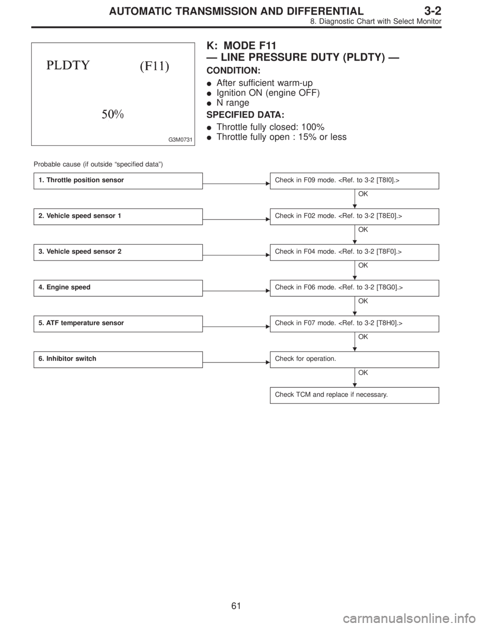
G3M0731
K: MODE F11
—LINE PRESSURE DUTY (PLDTY)—
CONDITION:
�After sufficient warm-up
�Ignition ON (engine OFF)
�N range
SPECIFIED DATA:
�Throttle fully closed: 100%
�Throttle fully open : 15% or less
Probable cause (if outside“specified data”)
1. Throttle position sensor
�Check in F09 mode.
OK
2. Vehicle speed sensor 1
�Check in F02 mode.
OK
3. Vehicle speed sensor 2
�Check in F04 mode.
OK
4. Engine speed
�Check in F06 mode.
OK
5. ATF temperature sensor
�Check in F07 mode.
OK
6. Inhibitor switch
�Check for operation.
OK
Check TCM and replace if necessary.
�
�
�
�
�
�
61
3-2AUTOMATIC TRANSMISSION AND DIFFERENTIAL
8. Diagnostic Chart with Select Monitor
Page 2467 of 3342
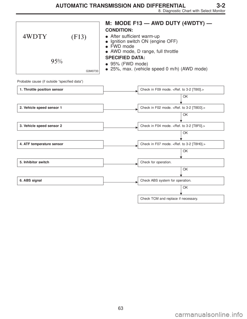
G3M0733
M: MODE F13—AWD DUTY (4WDTY)—
CONDITION:
�After sufficient warm-up
�Ignition switch ON (engine OFF)
�FWD mode
�AWD mode, D range, full throttle
SPECIFIED DATA:
�95% (FWD mode)
�25%, max. (vehicle speed 0 m/h) (AWD mode)
Probable cause (if outside“specified data”)
1. Throttle position sensor
�Check in F09 mode.
OK
2. Vehicle speed sensor 1
�Check in F02 mode.
OK
3. Vehicle speed sensor 2
�Check in F04 mode.
OK
4. ATF temperature sensor
�Check in F07 mode.
OK
5. Inhibitor switch
�Check for operation.
OK
6. ABS signal
�Check ABS system for operation.
OK
Check TCM and replace if necessary.
�
�
�
�
�
�
63
3-2AUTOMATIC TRANSMISSION AND DIFFERENTIAL
8. Diagnostic Chart with Select Monitor
Page 2468 of 3342
B3M0259
N: MODE F14
—THROTTLE POSITION SENSOR POWER
SUPPLY (THVCC)—
CONDITION:
Ignition switch ON (engine OFF)
SPECIFIED DATA:
5.12±0.1 V
Probable cause (Item outside“specified data”)
1. Throttle position sensor power supply
�Check throttle sensor line.
OK
Check TCM and replace if necessary.
B3M0370
O: MODE F15
—MASS AIR FLOW SIGNAL (AFM)—
CONDITION:
�Ignition switch ON (engine ON)
�N range
�Idling
SPECIFIED DATA:
Engine warm-up: 0.5—1.22 V
Probable cause (if outside“specified data”)
1. Mass air flow signal
�Check performance characteristics of mass air flow
signal.
OK
Check TCM and replace if necessary.
�
�
64
3-2AUTOMATIC TRANSMISSION AND DIFFERENTIAL
8. Diagnostic Chart with Select Monitor
Page 2471 of 3342
 Turn ignition switch OFF.
2) Disconnect connector from TCM.
3) Measure resistance of harness connector between
TCM and diagnosi")
B3M0373A
1. CHECK HARNESS CONNECTOR BETWEEN TCM
AND DIAGNOSIS SWITCH.
1) Turn ignition switch OFF.
2) Disconnect connector from TCM.
3) Measure resistance of harness connector between
TCM and diagnosis switch.
Connector & terminal / Specified resistance:
(B56) No. 6—(B82) No.5/1Ω, or less.
B3M0273B
4) Measure resistance of harness connector between
TCM and body to make sure that circuit does not short.
Connector & terminal / Specified resistance:
(B56) No.6—Body / 1 MΩ, or more
B3M0271B
2. CHECK INPUT SIGNAL FOR TCM.
1) Connect connector to TCM.
2) Turn ignition switch ON (with engine OFF).
3) Measure signal voltage for TCM while connecting and
disconnecting the diagnosis terminal to diagnosis connec-
tor.
Connector & terminal / Specified voltage:
(B56) No. 6—Body / Less than 1 V (Connected)
More than 6 V (Discon-
nected)
B4M0387A
3. CHECK DIAGNOSIS SWITCH GROUND LINE.
Measure resistance of harness terminal between diagnosis
terminal and body.
Connector & terminal / Specified resistance:
(B81)—Body / 1Ω, or less
67
3-2AUTOMATIC TRANSMISSION AND DIFFERENTIAL
8. Diagnostic Chart with Select Monitor
Page 2483 of 3342
Front left wheel P7 1�")
5. Control Module I/O Signal
1. I/O SIGNAL VOLTAGE
Contents Connector No. Terminal No.Input/Output signals
Measured value and measuring conditions
ABS
sensor
(Wheel
speed
sensor)Front left wheel P7 1—11 0.12—1 V (When it is 10 Hz.)
Front right wheel P6 8—16 0.12—1 V (When it is 10 Hz.)
Rear left wheel P6 7—15 0.12—1 V (When it is 10 Hz.)
Rear right wheel P7 2—12 0.12—1 V (When it is 10 Hz.)
Hydraulic
unitSolenoid
valveFront left outlet P4 1—GND
10—14 V when the valve is OFF.
Less than 1.5 V when the valve is ON. Front right outlet P5 3—GND
Rear left outlet P5 8—GND
Rear right outlet P4 3—GND
Front left inlet P4 2—GND
10—14 V when the valve is OFF.
Less than 1.0 V when the valve is ON. Front right inlet P5 2—GND
Rear left inlet P5 7—GND
Rear right inlet P4 4—GND
TCS 1 P4 5—GND
10—14 V when the valve is OFF.
Less than 1.0 V when the valve is ON.
TCS 2 P5 6—GND
Valve power supply P6 6—GND Ignition switch ON, 10—14 V
Valve relay power supply P6 1—GNDLess than 1.2 V when IGN is ON.
10—14 V when the system is down.
Motor relay power supply P6 9—GNDLess than 1.0 V when the motor is ON.
10—14 V when the motor is OFF.
Motor sensor signalsP7 3—GNDCyclic waveform of more than 180 Hz
when the motor across terminals is ON.
Less than 70 Hz when the motor is OFF. P7 13—GND
Pressure switch P7 6—GNDH/L toggle signal with the brake pedal off
(Cycle 14 mS, H: 10—14 V, L: less than
0.7 V). 10—14 V with the brake pedal
depressed.
Pedal
stroke
sensorOutput signals P7 5—GND 0.7—0.9 V with the brake pedal off.
Power supply P7 4—14 5±0.4 V
Stop light
switchSwitch P7 7—GNDLess than 2 V when the stop light is off.
10—12 V when the stop light is on.
Switch test signal P7 18—GNDH/L toggle signal with the brake pedal off
(Cycle 14 mS, H: 10—12 V, L: less than
0.7 V). Less than 2 V with the brake pedal
depressed.
TCS OFF switch P7 16—GNDLess than 2.0 V with the switch pressed
and 10—12 V with it released.
Indicator
lightTCS OFF P6 10—GND
Less than2Vwhenthelight is on and
10—12 V when it is off. TCS operation P6 11—GND
TCS warning P6 3—GND
ABS warning P6 2—GND
7
4-4bBRAKES
5. Control Module I/O Signal

1. Communication failure
(No communication method can be con")
—
CONDITION:
Ignition switch ON (engine OFF)
SPECIFIED DATA:
5.12±0.1 V
Probable cause (Item outside“specified data”)
1. Thro")