Page 2426 of 3342
 Connect connectors to TCM and transmission.
2) Lift-up the vehicle or set the vehicle on free roller.
CAUTION:
On AWD models, raise all wheels off")
OBD0607A
4. CHECK OUTPUT SIGNAL EMITTED FROM TCM.
1) Connect connectors to TCM and transmission.
2) Lift-up the vehicle or set the vehicle on free roller.
CAUTION:
On AWD models, raise all wheels off floor.
3) Start and warm-up the engine and transmission.
4) Push the TCS OFF switch to ON. (With TCS models)
5) Move selector lever to“D”and slowly increase vehicle
speed to 75 km/h (47 MPH).
6) Measure voltage between TCM connector terminals.
Connector & terminal / Specified voltage:
(B55) No. 5—No. 10 / 8.5 V, or more (when
wheels are locked-up.)
OBD0607A
7) Return the engine to idling speed and move selector
lever to“N”.
8) Measure voltage between TCM connector terminals.
Connector & terminal / Specified voltage:
(B55) No. 5—No. 10 / 0.5 V, or less
NOTE:
The speed difference between front and rear wheels may
light either the ABS or the ABS/TCS warning light, but this
indicates no malfunctions. When AT control diagnosis is
finished, perform the ABS or the ABS/TCS memory clear-
ance procedure of self-diagnosis system.
or 4-4d [T6D2] or [T9J0].>
OBD0145A
�Using Subaru select monitor:
(1) Connect connectors to TCM and transmission.
(2) Lift-up the vehicle or set the vehicle on free roller.
CAUTION:
On AWD models, raise all wheels off floor.
(3) Turn ignition switch to OFF.
(4) Connect the Subaru select monitor to data link con-
nector.
(5) Turn ignition switch to ON and Subaru select moni-
tor switch to ON.
22
3-2AUTOMATIC TRANSMISSION AND DIFFERENTIAL
7. Diagnostic Chart with Trouble Code
Page 2428 of 3342

C: TROUBLE CODE 13
—SHIFT SOLENOID 3—
DIAGNOSIS:
Output signal circuit of shift solenoid 3 is open or shorted.
TROUBLE SYMPTOM:
Ineffective engine brake with shift lever in“3”
1. Check harness and connectors between TCM
and shift solenoid 3.
OK
�Not OK
Repair or replace harness connectors.
2. Check shift solenoid 3’s ground line.
OK
�Not OK
Repair ground line.
3. Check shift solenoid 3.
OK
�Not OK
Replace shift solenoid 3.
4. Check output signal emitted from TCM.
OK
�Not OK
�Repair TCM connector terminal poor contact.
�Replace TCM.
�Repair TCM connector terminal poor contact.
OBD0452
OBD0454A
1. CHECK HARNESS AND CONNECTORS BETWEEN
TCM AND SHIFT SOLENOID 3.
1) Turn ignition switch to OFF.
2) Disconnect connectors from TCM and transmission.
3) Measure resistance of harness connector between
TCM and transmission connector.
Connector & terminal / Specified resistance:
(B55) No. 15—(B11)No.1/1Ω, or less
(B55) No. 10—(B11)No.4/1Ω, or less
�
�
�
�
24
3-2AUTOMATIC TRANSMISSION AND DIFFERENTIAL
7. Diagnostic Chart with Trouble Code
Page 2430 of 3342

D: TROUBLE CODE 14
—SHIFT SOLENOID 2—
DIAGNOSIS:
Output signal circuit of shift solenoid 2 is open or shorted.
TROUBLE SYMPTOM:
No shift
1. Check harness and connectors between TCM
and shift solenoid 2.
OK
�Not OK
Repair or replace harness connectors.
2. Check shift solenoid 2’s ground line.
OK
�Not OK
Repair ground line.
3. Check shift solenoid 2.
OK
�Not OK
Replace shift solenoid 2.
4. Check output signal emitted from TCM.
OK
�Not OK
�Repair TCM connector terminal poor contact.
�Replace TCM.
�Repair TCM connector terminal poor contact.
OBD0444
OBD0446A
1. CHECK HARNESS AND CONNECTORS BETWEEN
TCM AND SHIFT SOLENOID 2.
1) Turn ignition switch to OFF.
2) Disconnect connectors from TCM and transmission.
3) Measure resistance of harness connector between
TCM and transmission connector.
Connector & terminal / Specified resistance:
(B55) No. 13—(B11)No.2/1Ω, or less
(B55) No. 10—(B11)No.4/1Ω, or less
�
�
�
�
26
3-2AUTOMATIC TRANSMISSION AND DIFFERENTIAL
7. Diagnostic Chart with Trouble Code
Page 2432 of 3342

E: TROUBLE CODE 15
—SHIFT SOLENOID 1—
DIAGNOSIS:
Output signal circuit of shift solenoid 1 is open or shorted.
TROUBLE SYMPTOM:
No shift
1. Check harness and connectors between TCM
and shift solenoid 1.
OK
�Not OK
Repair or replace harness connectors.
2. Check shift solenoid 1’s ground line.
OK
�Not OK
Repair ground line.
3. Check shift solenoid 1.
OK
�Not OK
Replace shift solenoid 1.
4. Check output signal emitted from TCM.
OK
�Not OK
�Repair TCM connector terminal poor contact.
�Replace TCM.
�Repair TCM connector terminal poor contact.
OBD0436
OBD0438A
1. CHECK HARNESS AND CONNECTORS BETWEEN
TCM AND SHIFT SOLENOID 1.
1) Turn ignition switch to OFF.
2) Disconnect connectors from TCM and transmission.
3) Measure resistance of harness connector between
TCM and transmission connector.
Connector & terminal / Specified resistance:
(B55) No. 14—(B11)No.3/1Ω, or less
(B55) No. 10—(B11)No.4/1Ω, or less
�
�
�
�
28
3-2AUTOMATIC TRANSMISSION AND DIFFERENTIAL
7. Diagnostic Chart with Trouble Code
Page 2435 of 3342
 Turn ignition switch to OFF.
2) Disconnect connectors from TCM and transmission.
3) Measure resistance of harness co")
OBD0388A
1. CHECK HARNESS AND CONNECTORS BETWEEN
TCM AND ATF TEMPERATURE SENSOR.
1) Turn ignition switch to OFF.
2) Disconnect connectors from TCM and transmission.
3) Measure resistance of harness connector between
TCM and transmission connector.
Connector & terminal / Specified resistance:
(B54) No. 10—(B11)No.5/1Ω, or less
(B56) No. 20—(B11) No. 12 / 1Ω, or less
B3M0220B
4) Measure resistance of harness connector between
TCM and body to make sure that circuit does not short.
Connector & terminal / Specified resistance:
(B54) No. 10—Body/1MΩ, or more
(B56) No. 20—Body/1MΩ, or more
G3M0126
2. CHECK ATF TEMPERATURE SENSOR.
1) Measure resistance between transmission connector
receptacle’s terminals.
Connector & terminal / Specified resistance:
(T4) No. 5—No. 12 /
2.1—2.9 kΩ[ATF temperature: 20°C (68°F)]
2) Connect connectors to transmission and TCM.
3) Start and warm-up the engine until ATF temperature
has increased.
4) Stop the engine and disconnect connector from trans-
mission.
5) Measure resistance between transmission connector
receptacle’s terminals.
Connector & terminal / Specified resistance:
(T4) No. 5—No. 12 /
275—375Ω[ATF temperature: 80°C (176°F)]
31
3-2AUTOMATIC TRANSMISSION AND DIFFERENTIAL
7. Diagnostic Chart with Trouble Code
Page 2436 of 3342
 Turn ignition switch ON (with engine OFF) and measure
signal voltage input of TCM.
2) Start and warm-up the engine. Measure signal voltage
input of TCM.
Conn")
OBD0384A
3. CHECK INPUT SIGNAL FOR TCM.
1) Turn ignition switch ON (with engine OFF) and measure
signal voltage input of TCM.
2) Start and warm-up the engine. Measure signal voltage
input of TCM.
Connector & terminal / Specified voltage:
(B54) No. 10—(B56) No. 20 /
3.45±0.55 V [ATF temperature: 20°C (68°F)]
1.2±0.2 V [ATF temperature: 80°C (176°F)]
OBD0145A
�Using Subaru select monitor:
(1) Turn ignition switch to OFF.
(2) Connect the Subaru select monitor to data link con-
nector.
(3) Turn ignition switch to ON and Subaru select moni-
tor switch to ON.
OBD0386
OBD0387
(4) Start and warm-up the engine.
(5) Read data on Subaru select monitor.
(6) Designate mode using function key.
Function mode: F07 or F08
SPECIFIED DATA:
F07:�Ambient temperature: ±50 deg F
�ATF temperature: 158—230 deg F
�Open harness: 176 deg F
�Shorted harness: 320 deg F
F08:�Ambient temperature: ±10 deg C
�ATF temperature: 70—110 deg C
�Open harness: 80 deg C
�Shorted harness: 160 deg C
�F07: ATF temperature is indicated in“deg F”.
�F08: ATF temperature is indicated in“deg C”.
32
3-2AUTOMATIC TRANSMISSION AND DIFFERENTIAL
7. Diagnostic Chart with Trouble Code
Page 2438 of 3342
 Turn ignition switch to OFF.
2) Disconnect connectors from TCM and ECM.
3) Measure resistance of harness connector between
TCM and ECM.
Conn")
B3M0476A
2. CHECK HARNESS CONNECTOR BETWEEN TCM
AND ECM.
1) Turn ignition switch to OFF.
2) Disconnect connectors from TCM and ECM.
3) Measure resistance of harness connector between
TCM and ECM.
Connector & terminal / Specified resistance:
(B54) No. 9—(B84) No. 47 / 1Ω, or less
B3M0224B
4) Measure resistance of harness connector between
TCM and body to make sure that circuit does not short.
Connector & terminal / Specified resistance:
(B54) No. 9—Body/1MΩ, or more
B3M0222B
3. CHECK INPUT SIGNAL FOR TCM.
1) Connect connectors to TCM and ECM.
2) Start the engine. (engine idling after warm-up)
3) Measure signal voltage between TCM connector termi-
nal and body.
Connector & terminal / Specified voltage:
Engine warm-up;
(B54) No. 9—Body / 0.5—1.22 V
OBD0145A
�Using Subaru select monitor:
(1) Connect connectors to TCM and ECM.
(2) Turn ignition switch to OFF.
(3) Connect the Subaru select monitor to data link con-
nector.
(4) Turn ignition switch to ON and Subaru select moni-
tor switch to ON.
(5) Start and warm-up the engine.
B3M0370
(6) Read data on Subaru select monitor.
(7) Designate mode using function key.
Function mode: F15
SPECIFIED DATA:
0.5—1.22 V (Engine warm-up)
34
3-2AUTOMATIC TRANSMISSION AND DIFFERENTIAL
7. Diagnostic Chart with Trouble Code
Page 2439 of 3342
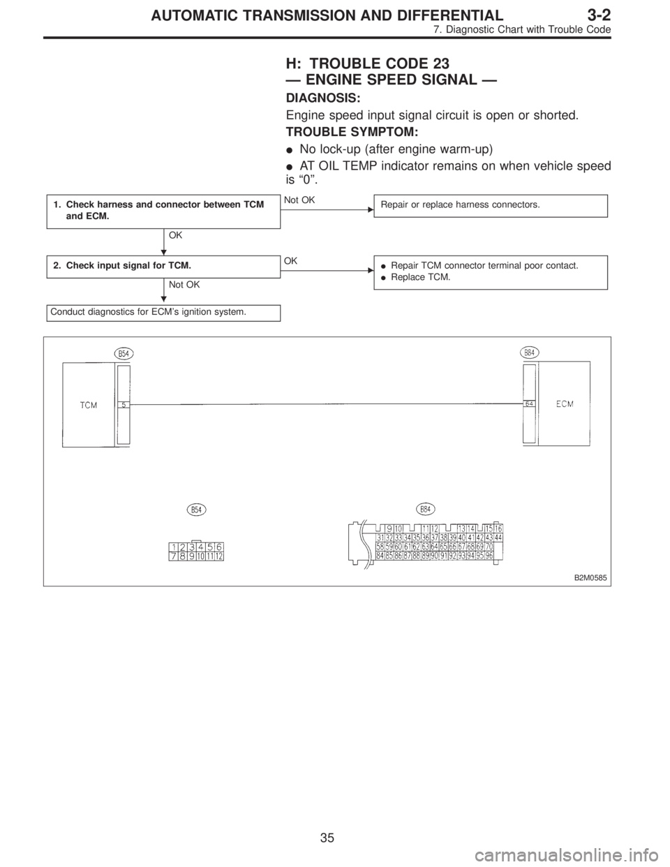
H: TROUBLE CODE 23
—ENGINE SPEED SIGNAL—
DIAGNOSIS:
Engine speed input signal circuit is open or shorted.
TROUBLE SYMPTOM:
�No lock-up (after engine warm-up)
�AT OIL TEMP indicator remains on when vehicle speed
is“0”.
1. Check harness and connector between TCM
and ECM.
OK
�Not OK
Repair or replace harness connectors.
2. Check input signal for TCM.
Not OK
�OK
�Repair TCM connector terminal poor contact.
�Replace TCM.
Conduct diagnostics for ECM’s ignition system.
B2M0585
�
�
35
3-2AUTOMATIC TRANSMISSION AND DIFFERENTIAL
7. Diagnostic Chart with Trouble Code