Page 628 of 3342
G2M0294
6) Install torque converter to drive plate. (AT model)
(1) Tighten bolts which hold torque converter to drive
plate.
(2) Tighten other bolts while rotating the engine by
using ST.
ST 499977000 CRANK PULLEY WRENCH
CAUTION:
Be careful not to drop bolts into torque converter
housing.
Tightening torque:
25±2 N⋅m (2.5±0.2 kg-m, 18.1±1.4 ft-lb)
(3) Clog plug onto service hole.
B2M0017
(4) Install V-belt cover.
B2M1179B
7) Install operating cylinder. (Hydraulic clutch model)
Tightening torque:
37±3 N⋅m (3.8±0.3 kg-m, 27.5±2.2 ft-lb)
G2M0313
8) Remove special tools.
40
2-11SERVICE PROCEDURE
3. Transmission
Page 629 of 3342
G2M0302
9) Install pitching stopper.
Tightening torque:
T1: 49±5 N⋅m (5.0±0.5 kg-m, 36.2±3.6 ft-lb)
T2: 57±10 N⋅m (5.8±1.0 kg-m, 42±7 ft-lb)
G2M0325
10) Install front drive shafts into transmission.
(1) Lift-up the vehicle.
(2) Install front drive shaft into transmission.
(3) Drive spring pin into chamfered hole of drive shaft.
CAUTION:
Always use a new spring pin.
G2M0324
(4) Install ball joints of lower arm into knuckle arm of
housing, and tighten installing bolts.
Tightening torque:
49±10 N⋅m (5.0±1.0 kg-m, 36±7 ft-lb)
G2M0323
11) Install stabilizer clamps onto front crossmember.
Tightening torque:
25±4 N⋅m (2.5±0.4 kg-m, 18.1±2.9 ft-lb)
G3M0697
12) Install gear shift rod and stay. (MT model)
(1) Install gear shift rod onto transmission.
(2) Install stay onto transmission.
(3) Install spring.
41
2-11SERVICE PROCEDURE
3. Transmission
Page 630 of 3342
B2M0033A
13) Install shift selector cable onto selector lever. (AT
model)
(1) Install selector cable into selector lever.
(2) Install cable bracket onto body.
NOTE:
Tighten selector cable adjusting and lock nut after check-
ing selector lever operation.
G2M0317
14) Install ATF level gauge guide, and ATF cooler hoses
onto pipe. (AT model)
G3M0023
15) Install propeller shaft. (AWD model)
(1) Install propeller shaft into transmission.
(2) Tighten bolts which install propeller shaft onto com-
panion flange of rear differential.
Tightening torque:
31±8 N⋅m (3.2±0.8 kg-m, 23.1±5.8 ft-lb)
G3M0024
(3) Install center bearing bracket on body.
Tightening torque:
52±5 N⋅m (5.3±0.5 kg-m, 38.3±3.6 ft-lb)
G2M0830
16) Install exhaust system.
(1) Install heat shield cover. (AWD model)
42
2-11SERVICE PROCEDURE
3. Transmission
Page 631 of 3342
G2M0382
(2) Install rear exhaust pipe to muffler. (AWD model)
Tightening torque:
48±9 N⋅m (4.9±0.9 kg-m, 35.4±6.5 ft-lb)
B2M0032
(3) Install hanger bracket on right side of transmission.
(AWD model)
G2M0290
(4) Install front exhaust pipe onto engine.
Tightening torque:
30±5 N⋅m (3.1±0.5 kg-m, 22.4±3.6 ft-lb)
G2M0291
(5) Install center exhaust pipe to rear exhaust pipe.
Tightening torque:
18±5 N⋅m (1.8±0.5 kg-m, 13.0±3.6 ft-lb)
B2M0313
(6) Tighten bolt which installs center exhaust pipe to
hanger bracket.
Tightening torque:
30±5 N⋅m (3.1±0.5 kg-m, 22.4±3.6 ft-lb)
43
2-11SERVICE PROCEDURE
3. Transmission
Page 632 of 3342
B2M0335
(7) Connect connector to rear oxygen sensor.
B2M1300A
17) Install clutch damper. (Hydraulic clutch model)
Tightening torque:
25±7 N⋅m (2.5±0.7 kg-m, 18.1±5.1 ft-lb)
G2M0312
18) Install transmission connector holder bracket.
B2M0031
19) Install ATF level gauge. (AT model)
44
2-11SERVICE PROCEDURE
3. Transmission
Page 633 of 3342
20) Connect connectors and cables.
(1) Connect the following connectors.
�Transmission harness connectors
�Transmission ground terminal
�Front oxygen sensor connector
�Vehicle speed sensor 2
�Neutral position switch connector (MT model)
�Back-up light switch connector (MT model)
(2) Connect the following cables.
�Cruise control cable
(With cruise control model)
�Clutch cable
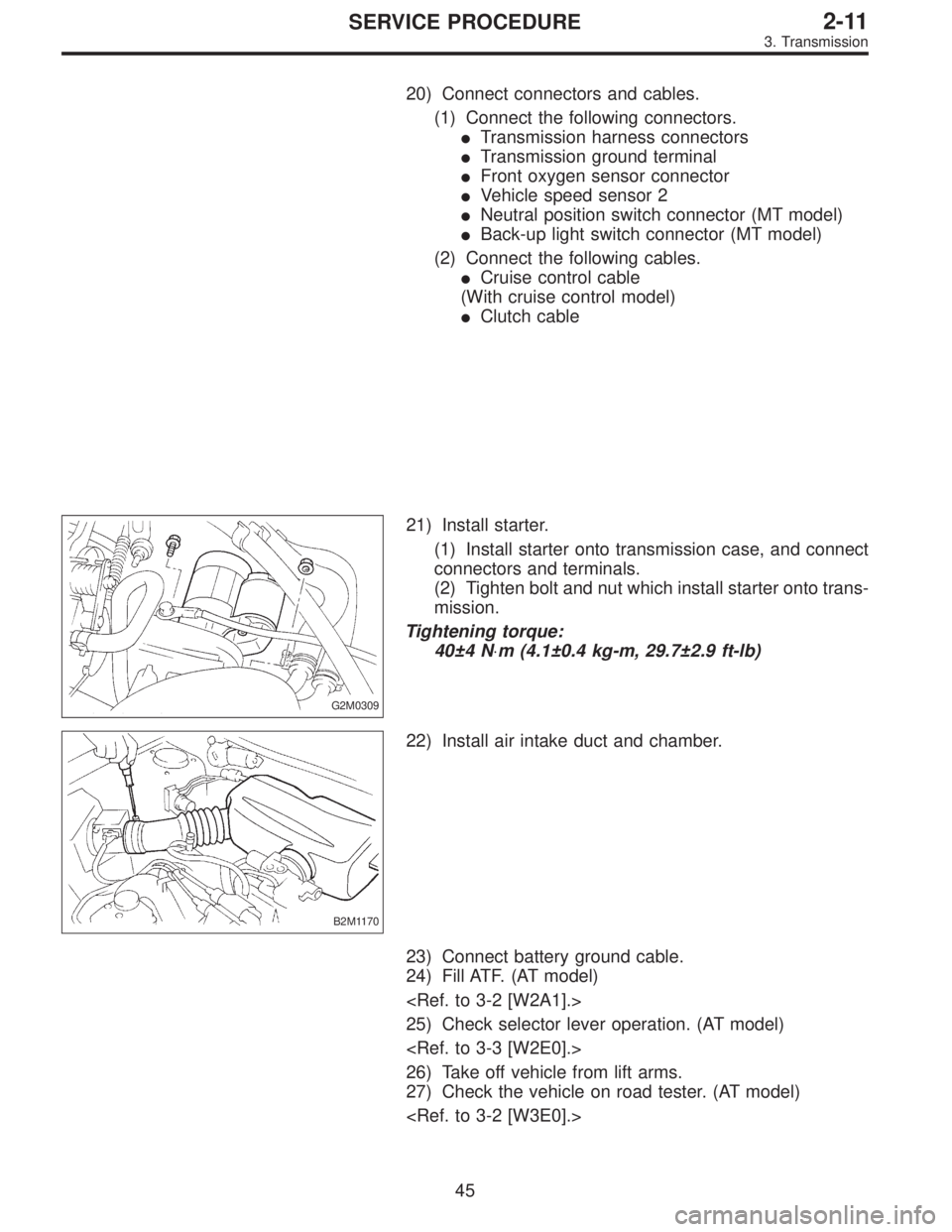
G2M0309
21) Install starter.
(1) Install starter onto transmission case, and connect
connectors and terminals.
(2) Tighten bolt and nut which install starter onto trans-
mission.
Tightening torque:
40±4 N⋅m (4.1±0.4 kg-m, 29.7±2.9 ft-lb)
B2M1170
22) Install air intake duct and chamber.
23) Connect battery ground cable.
24) Fill ATF. (AT model)
25) Check selector lever operation. (AT model)
26) Take off vehicle from lift arms.
27) Check the vehicle on road tester. (AT model)
45
2-11SERVICE PROCEDURE
3. Transmission
Page 634 of 3342
1. Manual Transmission and
Differential
A: SPECIFICATIONS
ItemModel
2200 cc 2500 cc OUTBACK
Type 5-forward speeds with synchromesh and 1-reverse
Transmission gear ratio1st 3.545
2nd 2.111
3rd 1.448
4th 1.088
5th 0.780 0.871
Reverse 3.416
Front
reduction
gearFinalType of gear Hypoid
Gear ratio 3.900 4.111
Rear
reduction
gearTransferType of gear Helical
Gear ratio 1.000
FinalType of gear Hypoid
Gear ratio 3.900 4.111
Front
differentialType and number of gear Straight bevel gear (Bevel pinion: 2, Bevel gear: 2)
Center
differentialType and number of gear Straight bevel gear (Bevel pinion: 2, Bevel gear: 2 and viscous coupling)
Transmission gear oil GL-5
Transmission oil capacity 3.5�(3.7 US qt, 3.1 Imp qt)
2
3-1SPECIFICATIONS AND SERVICE DATA
1. Manual Transmission and Differential
Page 635 of 3342

Snap ring (Inner-72) to ball bearing side clearance
0 — 0.15 mm (0 — 0.0059 in)
Snap ring (Inner-72)
Part No. Thickness mm (in)
805172071 1.78 (0.0701)
805")
B: SERVICE DATA
1. EXTENSION (AWD Model)
Snap ring (Inner-72) to ball bearing side clearance
0 — 0.15 mm (0 — 0.0059 in)
Snap ring (Inner-72)
Part No. Thickness mm (in)
805172071 1.78 (0.0701)
805172072 1.90 (0.0748)
805172073 2.02 (0.0795)
Snap ring (Outer-30) to ball bearing side clearance
0 — 0.15 mm (0 — 0.0059 in)
Snap ring (Outer-30)
Part No. Thickness mm (in)
805030041 1.53 (0.0602)
805030042 1.65 (0.0650)
805030043 1.77 (0.0697)
2. EXTENSION ASSEMBLY (AWD Model)
Thrust washer (52 x 61 x t) to ball bearing side clearance
0.05 — 0.30 mm (0.0020 — 0.0118 in)
Thrust washer (52 x 61 x t)
Part No. Thickness mm (in)
803052021 0.50 (0.0197)
803052022 0.75 (0.0295)
803052023 1.00 (0.0394)
3. TRANSFER CASE OR REAR CASE
Neutral position adjustment
Adjustment shim
Part No. Thickness mm (in)
32190AA000 0.15 (0.0059)
32190AA010 0.30 (0.0118)
Reverse accent shaft
Part No. Mark Remarks
32188AA040 1Neutral position is closer to
1st.
32188AA011 No mark or 2 Standard
32188AA050 3Neutral position is closer to
reverse gear.
Reverse check plate adjustment
Reverse check plate
Part No. Mark AngleθRemarks
32189AA000 0 28°Arm stops closer to
5th gear.
32189AA010 1 31°Arm stops closer to
5th gear.
33189AA020 2 34°Arm stops in the
center.
32189AA030 3 37°Arm stops closer to
reverse gear.
32189AA040 4 40°Arm stops closer to
reverse gear.
4. REVERSE IDLER GEAR
Adjustment of reverse idler gear position
Reverse idler gear to transmission case (LH) wall clearance
6.0 — 7.5 mm (0.236 — 0.295 in)
Reverse shifter lever
Part No. Mark Remarks
32820AA000 0 Further from case wall
32820AA010 No mark Standard
32820AA020 2 Closer to the case wall
After installing a suitable reverse shifter lever, adjust reverse idler
gear to transmission case wall clearance to within 0 to 0.5 mm (0
to 0.020 in) using washers.
Washer (20.5 x 26 x t)
Part No.Thickness
mm (in)Part No.Thickness
mm (in)
803020151 0.4 (0.016) 803020154 1.9 (0.075)
803020152 1.1 (0.043) 803020155 2.3 (0.091)
803020153 1.5 (0.059)
3
3-1SPECIFICATIONS AND SERVICE DATA
1. Manual Transmission and Differential
 Install torque converter to drive plate. (AT model)
(1) Tighten bolts which hold torque converter to drive
plate.
(2) Tighten other bolts while rotating the engine by
using ST.
ST 499977000")
 Install pitching stopper.
Tightening torque:
T1: 49±5 N⋅m (5.0±0.5 kg-m, 36.2±3.6 ft-lb)
T2: 57±10 N⋅m (5.8±1.0 kg-m, 42±7 ft-lb)
G2M0325
10) Install front drive shafts into trans")
 Install shift selector cable onto selector lever. (AT
model)
(1) Install selector cable into selector lever.
(2) Install cable bracket onto body.
NOTE:
Tighten selector cable adjusting an")
 Install rear exhaust pipe to muffler. (AWD model)
Tightening torque:
48±9 N⋅m (4.9±0.9 kg-m, 35.4±6.5 ft-lb)
B2M0032
(3) Install hanger bracket on right side of transmission.
(AWD mod")
 Connect connector to rear oxygen sensor.
B2M1300A
17) Install clutch damper. (Hydraulic clutch model)
Tightening torque:
25±7 N⋅m (2.5±0.7 kg-m, 18.1±5.1 ft-lb)
G2M0312
18) Install tr")