Page 140 of 3342
BRAKES
[ABS
5
.3i
TYPE]
[T10L0]4-4d
10
.
Diagnostics
Chart
withSelect
Monitor
DIAGNOSIS
:
"
Faulty
ABS
sensor
signal
(noise,
irregular
signal,
etc
.)
Faulty
harness/connector
TROUBLE
SYMPTOM
:
e
ABS
does
not
operate
.
WIRING
DIAGRAM
:
9
ABS
control
module
and
hydraulic
control
unit
Twisted
wire
Ft
0
8100
815
Front
ASS
sensorLH
RearABS
sensorLH
Rear
ABS
sensor
RH
r----------------
1
OUTBACK
with
step
roof
model
I
I
Q
I
RearABS
7
sensor
LH
I
~
III
j
~
Rear
ASS
j
sensor
RH
I
O
I
L---
.
.
.---------J
OUTBACK
with
steproof
model
B~5
O
OOOO
fl
(i~]
DO`]
478
1
10
F49
1234567891011131415
1617181920
1
212
23
4
5
26
218930
13
1
1
B4M1238
Front
ASS
sensor
RH
123
Page 145 of 3342
4-4d
[T1oLis1
BRAKES
[ABS
5
.3i
TYPE]
10
.
Diagnostics
Chart
withSelect
Monitor
Except
OUTBACK
model
1
2
D
S2
B4M0806E
OUTBACK
model
Front
Rear
1
22
1
i
J
D
.0
0
.
B4M1036C
Except
OUTBACK
model
1
2
L
j
B4M0818E
OUTBACK
model
Front
Rear
1
22
1
D
134M
1042C
10L16
CHECK
RESISTANCE
OF
ABS
SENSOR
.
1)
Turn
ignition
switch
OFF
.
2)
Disconnect
connector
from
ABS
sensor
.
3)
Measure
resistance
between
ABS
sensor
connector
ter-
minals
.
Terminal
Front
RH
No
.
1
-
No
.
2
:
Front
LHNo
.
1
-
No
.
2
:
Rear
RHNo
.
1
-
No
.
2
:
Rear
LHNo
.
1
-
No
.
2
:
cF+ECK
:
Is
the
resistance
between
0
.8
and
1
.2
kS2?
Go
to
step
10L17
.
No
:
Replace
ABS
sensor
.
10L17
CHECK
GROUND
SHORT
OF
ABS
SENSOR
.
Measure
resistance
between
ABS
sensor
and
chassis
ground
.
Terminal
Front
RH
No
.
1
-
Chassis
ground
:
Front
LHNo
.
1
-
Chassis
ground
:
Rear
RH
No
.
1
-
Chassis
ground
:
Rear
LH
No
.
1
-
Chassis
ground
:
CHECK
;
Is
the
resistance
more
than1
MW
Go
to
step
10L18
.
No
:
Replace
ABS
sensor
.
128
Page 149 of 3342
4-4d
[T1onno]
BRAKES
[ABS
5
.3i
TYPE]
10
.
Diagnostics
Chart
withSelect
Monitor
D
"
NEW
29
EITHER
.
SS
(FBI)
SOFT
84M0952
J
M
:
TROUBLE
CODE
29
EITHER
.
SS
SOFT
-
ABNORMAL
ABS
SENSOR
SIGNAL
(ANY
ONE
OF
FOUR)
-
DIAGNOSIS
:
"
Faulty
ABS
sensor
signal
(noise,
irregular
signal,
etc
.)
"
Faulty
tone
wheel
"
Wheels
turning
freely
for
a
long
time
TROUBLE
SYMPTOM
:
9
ABS
does
not
operate
.
WIRING
DIAGRAM
:
F19
ABS
control
module
and
hydraulic
control
unit
OUTBACK
withsteproof
model
(2D(E)(~D
QD
rll~9
No"111
100
--------
Front
ABS
F
V
----------
;
sensorl-H
LjJF
---
----------
Front
ABS
Twisted
-----
sensor
RH
wire
Ft
Pt
OO
RearABS
--~
sensor
LH
Twisted
wire
Rear
ABS
41
4
.
sensor
RH
P8
r----------------
I
OUTBACK
with
steproof
model
IIII
O~
I
RearABS
sensorLH
j
~
Rear
ABS
j
sensor
RH
I
~
I
L---------------J
Ft
8100
1121
3
1
10
45
78
f49
123456789101112131415
16171819
20
2122
23
2425
26
2728293031
B4M1238
132
Page 172 of 3342

BRAKES
[ABS
5
.31
TYPE]
[T10Y3]
4-4d
10
.
Diagnostics
Chart
withSelect
Monitor
1997
(F00)
AB
S
4WD
"
AT
H4M
1117'
B56
110191817
1
6
5
43
2
1
0
1
91
1
0
1
71
1
1
4i
1
1211
0
L
V
84M
1251
A
1
CHECK
I
USING
SELECT
.
1)
Press
[F],[0]
and
[0]
on
the
select
monitor
.
2)
Read
the
select
monitor
display
.
CHECK
:
Is
an
ABSCM&HI
U
for
AT
model
installed
on
a
MT
model?
vES
:
Replace
ABSCM&H/U
.
No
:
Go
tostep
10Y2
.
1
10Y2
I
CHECK
GROUND
SHORT
OF
HARNESS
.
1)
Turn
ignition
switch
to
OFF
.
2)
Disconnect
two
connectors
from
TCM
.
3)
Disconnect
connector
from
ABSCM&H/U
.
4)
Measure
resistance
between
ABSCM&H/U
connector
and
chassis
ground
.
Connector
&
terminal
(F49)
No
.
3
-
Chassis
ground
:
CHECK
:
Is
the
resistance
more
than
1
1140?
,rES
:
Go
to
step
10Y3
.
No
:
Repair
harness
between
TCM
and
ABSCM&H/U
.
10Y3
CHECK
TCM
.
1)
Connect
all
connectors
to
TCM
.
2)
Turn
ignition
switch
to
ON
.
3)
Measure
voltage
between
TCM
connector
terminal
and
chassis
ground
.
Connector
&
terminal
(B55)
No
.
5
(+)
-
Chassis
ground
(
)
:
CHECK
:
Is
thevoltage
between
10
V
and
15
V?
Go
to
step
10Y5
.
No
:
Go
tostep
10Y4
.
159
Page 195 of 3342

BRAKES
[ABS
5
.31
TYPE]
[T10AG5]
4-4d
10
.
DiagnosticsChart
with
Select
Monitor
1997
(F00)
ABS
4WD
"
AT
H4M
11171
G-SENS
(F
10)
2
.30
V
sannos271
10AG1
HECK
I
US
G
SE
ECT,MONT
OR
OF
ABSCM&H/U
1)
Press
[F],
[0]
and
[0]
on
the
select
monitor
.
2)
Read
the
select
monitor
display
.
CH~K
:
Is
an
ABSCM&HlU
for
4WD
model
installed
on
a
FWD
model?
Replace
ABSCM&H/U
.
No
:
Go
to
step
10AG2
.
I10AG2
CHECK
OUTPUT
I
SELECT
MONITOR
F
G
SENSOR
USING
1)
Press
[F],
[1]
and
[0]
on
the
select
monitor
.
2)
Read
the
select
monitor
display
.
K
:
Is
theindicated
reading
between
2
.1
and
2
.5
V
when
the
G
sensor
is
in
horizontal
posi-
tion?
,rE$
:
Go
to
step
10AG3
.
Go
to
step
10AG6
.
I
10AG3
I
CHECK
POOR
CONTACT
IN
CONNECTORS
.
CHECK
:
Is
there
poor
contact
in
connector
between
ABSCM&HIU
and
G
sensor?
<
Ref
.
to
FORE-
WORD
[T3C1]
.*10
>
Repair
connector
.
No
:
Go
tostep
10AG4
.
10AG4
CHECK
ABSCM&HlU
.
1)
Connect
all
connectors
.
2)
Erase
the
memory
.
3)
Perform
inspection
mode
.
4)
Read
out
the
trouble
code
.
c
:
Is
the
same
trouble
code
as
in
thecurrent
diagnosis
still
being
output?
Replace
ABSCM&H1U
.
No
:
Go
to
step
i0AG5
.
10AG5
CHECK
ANY
I
APPEARANCE
.THER
TROUBLE
CODES
CHECK
:
Are
other
trouble
codes
being
output?
Proceed
withthe
diagnosis
corresponding
to
the
trouble
code
.
A
temporary
poor
contact
.
187
Page 217 of 3342
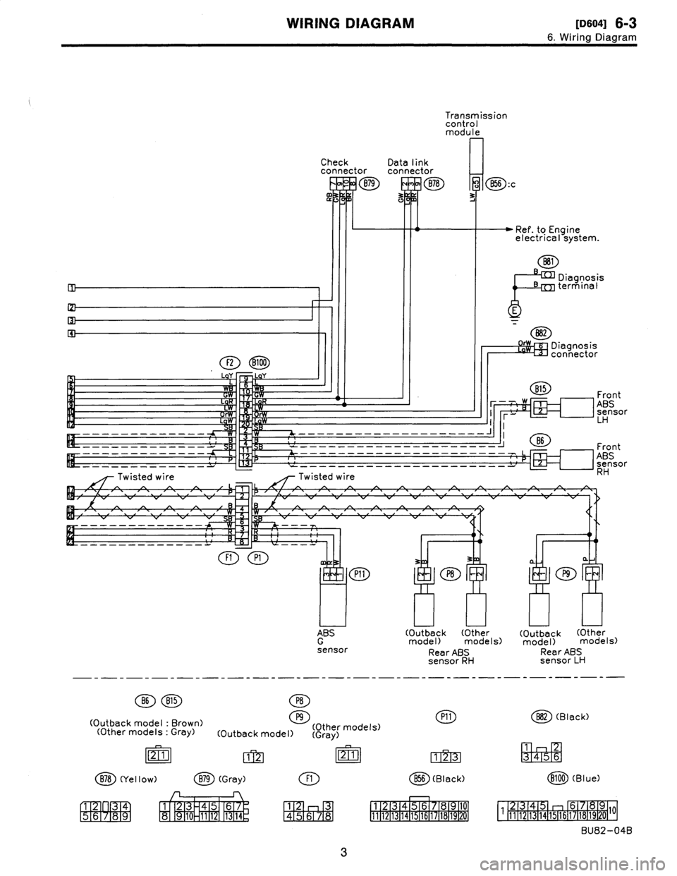
WIRING
DIAGRAM
[osoa1
6-3
6
.
Wiring
Diagram
F2
100
Twisted
wire
LL
7
-
---
-
---------
-
FtP1
Transmission
control
module
Check
Data
link
connectorconnector
879
EEE
878
a
B56
:c
Ref
.
to
Engine
electrical
system
.
881
Diagnosis
PEterminal
B82
Q1
-
Diagnosis
connector
Front
~--~~
ABS
sensorLH
II
---------------
------_-----_--_----_J
Twisted
wire
ABS
G
sensor
86
B15
P8
(Outback
model
:
Brown)
O
(Other
models
:
Gray)
(Other
models)
(Outback
model)
(Gray)
86
Front
m--F-I
ABS
sensor
RH
n
(Outback
(Other
(Outback
(Other
model)
models)
model)
models)
RearABS
Rear
ABS
sensor
RH
sensor
LH
------------------
P11
1
01
P-am
B78
(Yellow)
879
(Gray)
F1
856
(Black)
1
4
1
4
56
10131
1
1
12131
45
6
8
10
56
88
99
10
111
1314
45678
1
11
1
12
1
13
1
14
1
15
1
16
11
/1
16
1
19
12U]
B82
(Black)
1
456
8100
(Blue)
4
6
171619
111
1
1415161
18192010BU82-04B
3
Page 220 of 3342
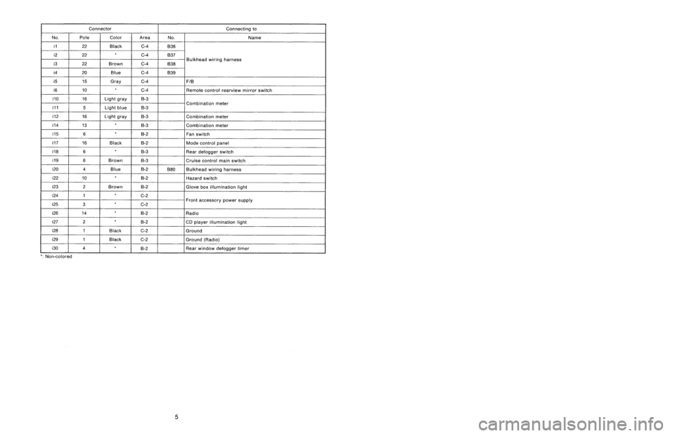
Connector
Connecting
to
No
.
Pole
Color
Area
No
.
Name
i1
22
Black
C-4
B36
i2
22
G4
B37
i3
22
Brown
C-4
B38
Bulkhead
wiring
harness
i4
20
Blue
C-4
B39
i5
15
Gray
C-4F!B
i6
10
C-4
Remote
control
rearview
mirror
switch
i10
16
Light
gray
B-3
i11
5
Light
blueB-3
Combination
meter
i12
16
Light
gray
B-3
Combination
meter
04
13
B-3
Combination
meter
05
6B-2
Fan
switch
07
16
Black
B-2
Mode
control
panel
08
6B-3
Rear
defogger
switch
09
6
Brown
B-3Cruise
control
main
switch
i20
4
Blue
B-2
B80
Bulkhead
wiring
harness
i22
10
B-2
Hazard
switch
i23
2
Brown
B-2
Glove
box
illumination
light
i24
1
G2
i25
3C-2Front
accessory
power
supply
i26
14
B-2
Radio
i27
2B-2
CD
player
illumination
light
i28
1
Black
C-2
Ground
i29
1
Black
C-2
Ground
(Radio)
i30
4B-2
Rear
window
defogger
timer
'
:
Non-colored
5
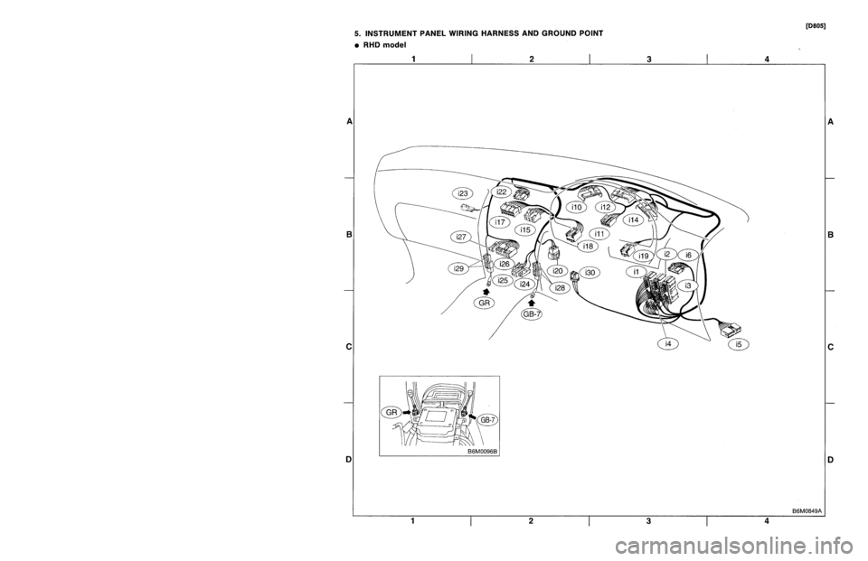
.
INSTRUMENT
PANEL
WIRING
HARNESS
AND
GROUND
POINT
9
RHD
model
1
23
AI
B
C
DI
1
2
3
5
Page 221 of 3342
Connector
Connecting
to
ole
Color
Area
No
.
Name
22
Black
C-4
B36
22
C-4
B37
lkh
ii
h
?2
Brown
C-4
B38
ead
w
r
ng
arness
Bu
20
Blue
C-4
B39
15
Gray
C-4
FIB
10
C-4
Remote
control
rearview
mirrorswitch
16
Light
gray
B-3
ii
5
Light
blue
B-3
Comb
nat
on
meter
16
Light
gray
B-3
Combination
meter
13
B-3
Combination
meter
6
B-2
Fan
switch
16
Black
B-2
Mode
control
panel
6
B-3
Rear
defogger
switch
6
Brown
B-3
Cruise
control
main
switch
4
Blue
B-2
B80
Bulkhead
wiring
harness
10
B-2
Hazard
switch
2
Brown
B-2
Glove
box
illumination
light
1
G2
F3
G2
ront
accessory
power
supply
14
8-2
Radio
2B-2
CD
player
illumination
light
1
Black
C-2
Ground
1
Black
G2
Ground
(Radio)
4
B-2
Rear
window
defogger
timer
5
.
INSTRUMENT
PANEL
WIRING
HARNESS
AND
GROUND
POINT
e
RHD
model
1
I
2
I
3
A
B
C
D
1
2
3
4
4
[D805]
B6M0849A
A
B
C
C
5

![SUBARU LEGACY 1997 Service Repair Manual
4-4d
[T1oLis1
BRAKES
[ABS
5
.3i
TYPE]
10
.
Diagnostics
Chart
withSelect
Monitor
Except
OUTBACK
model
1
2
D
S2
B4M0806E
OUTBACK
model
Front
Rear
1
22
1
i
J
D
.0
0
.
B4M1036C
Except
OUTBACK](/manual-img/17/57434/w960_57434-144.png "SUBARU LEGACY 1997 Service Repair Manual
4-4d
[T1oLis1
BRAKES
[ABS
5
.3i
TYPE]
10
.
Diagnostics
Chart
withSelect
Monitor
Except
OUTBACK
model
1
2
D
S2
B4M0806E
OUTBACK
model
Front
Rear
1
22
1
i
J
D
.0
0
.
B4M1036C
Except
OUTBACK")