Page 988 of 3342
B3M0630A
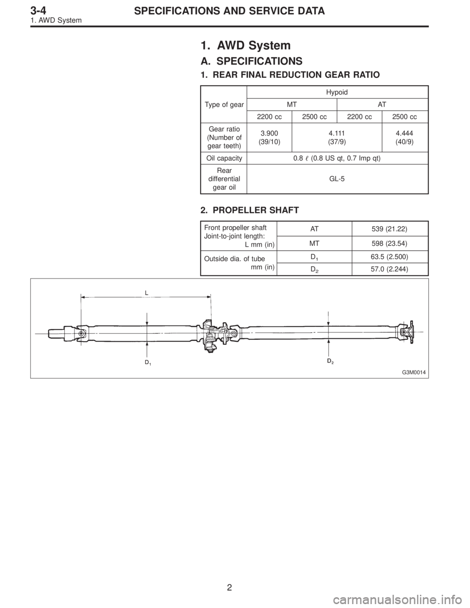
11) Insert the input shaft while turning lightly by hand.
CAUTION:
Be careful not to damage the bushing.
Normal protrusion A:
2200 cc: 50—55 mm (1.97—2.17 in)
2500 cc: 28—32 mm (1.10—1.26 in)
B3M0632A
12) Install the torque converter clutch assembly.
(1) Install the oil pump shaft to the torque converter
clutch.
NOTE:
Make sure the clip fits securely in its groove.
(2) Holding the torque converter clutch assembly by
hand, carefully install it to the torque converter clutch
case. Be careful not to damage the bushing. Also avoid
undue contact between the oil pump shaft bushing and
stator shaft portion of the oil pump cover.
(3) Rotate the shaft lightly by hand to engage the
splines securely.
Dimension A:
2200 cc: 3.9—4.1 mm (0.154—0.161 in)
2500 cc: 7.9—8.1 mm (0.311—0.319 in)
13) Fill ATF and differential gear oil.
Differential gear oil capacity:
1.1—1.3�(1.2—1.4 US qt, 1.0—1.1 Imp qt)
Automatic transmission fluid capacity:
2200 cc:
7.9—8.2�(8.4—8.7 US qt, 7.0—7.2 Imp qt)
2500 cc:
9.5—9.8�(10.0—10.3 US qt, 8.4—8.6 lmp qt)
Recommended fluid:
Dexron II or Dexron III type automatic transmis-
sion
NOTE:
After filling oil, insert the oil level gauge into the oil inlet.
82
3-2SERVICE PROCEDURE
4. Overall Transmission
Page 1040 of 3342
1. AWD System
A. SPECIFICATIONS
1. REAR FINAL REDUCTION GEAR RATIO
Type of gearHypoid
MT AT
2200 cc 2500 cc 2200 cc 2500 cc
Gear ratio
(Number of
gear teeth)3.900
(39/10)4 . 111
(37/9)4.444
(40/9)
Oil capacity 0.8�(0.8 US qt, 0.7 Imp qt)
Rear
differential
gear oilGL-5
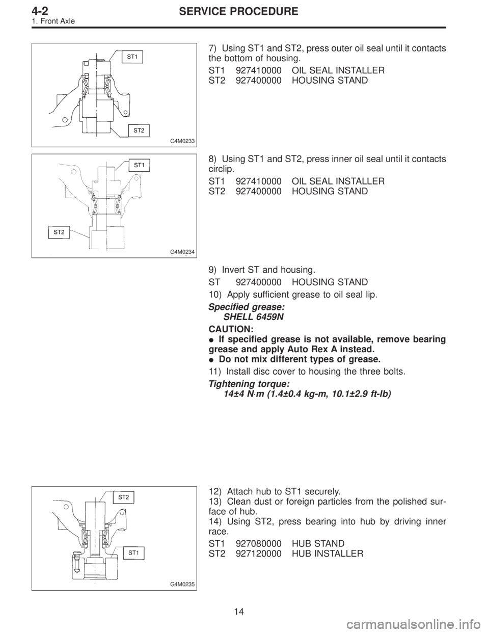
2. PROPELLER SHAFT
Front propeller shaft
Joint-to-joint length:
L mm (in)AT 539 (21.22)
MT 598 (23.54)
Outside dia. of tube
mm (in)D
163.5 (2.500)
D
257.0 (2.244)
G3M0014
2
3-4SPECIFICATIONS AND SERVICE DATA
1. AWD System
Page 1139 of 3342
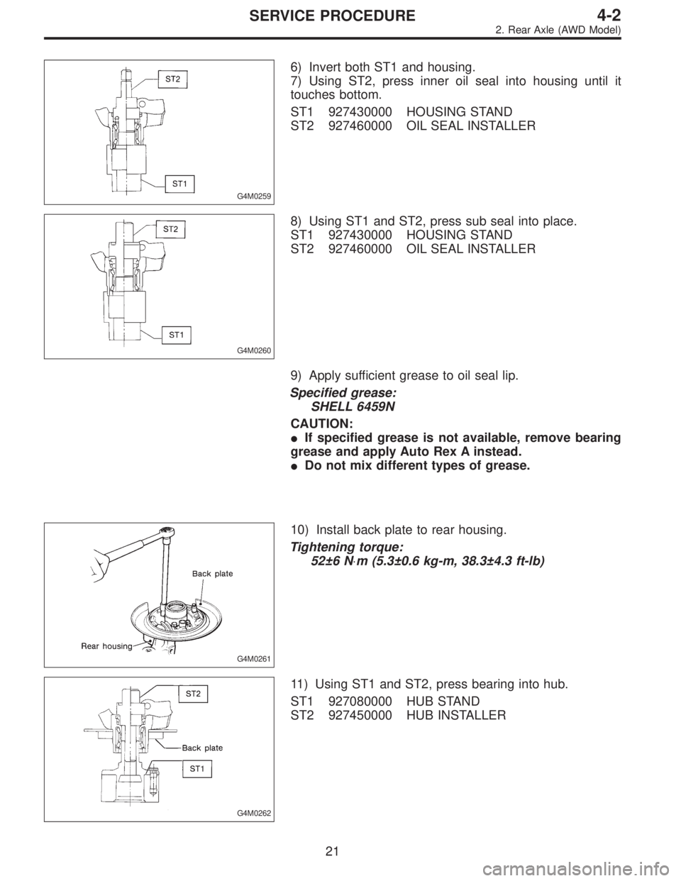
G4M0233
7) Using ST1 and ST2, press outer oil seal until it contacts
the bottom of housing.
ST1 927410000 OIL SEAL INSTALLER
ST2 927400000 HOUSING STAND
G4M0234
8) Using ST1 and ST2, press inner oil seal until it contacts
circlip.
ST1 927410000 OIL SEAL INSTALLER
ST2 927400000 HOUSING STAND
9) Invert ST and housing.
ST 927400000 HOUSING STAND
10) Apply sufficient grease to oil seal lip.
Specified grease:
SHELL 6459N
CAUTION:
�If specified grease is not available, remove bearing
grease and apply Auto Rex A instead.
�Do not mix different types of grease.
11) Install disc cover to housing the three bolts.
Tightening torque:
14±4 N⋅m (1.4±0.4 kg-m, 10.1±2.9 ft-lb)
G4M0235
12) Attach hub to ST1 securely.
13) Clean dust or foreign particles from the polished sur-
face of hub.
14) Using ST2, press bearing into hub by driving inner
race.
ST1 927080000 HUB STAND
ST2 927120000 HUB INSTALLER
14
4-2SERVICE PROCEDURE
1. Front Axle
Page 1147 of 3342
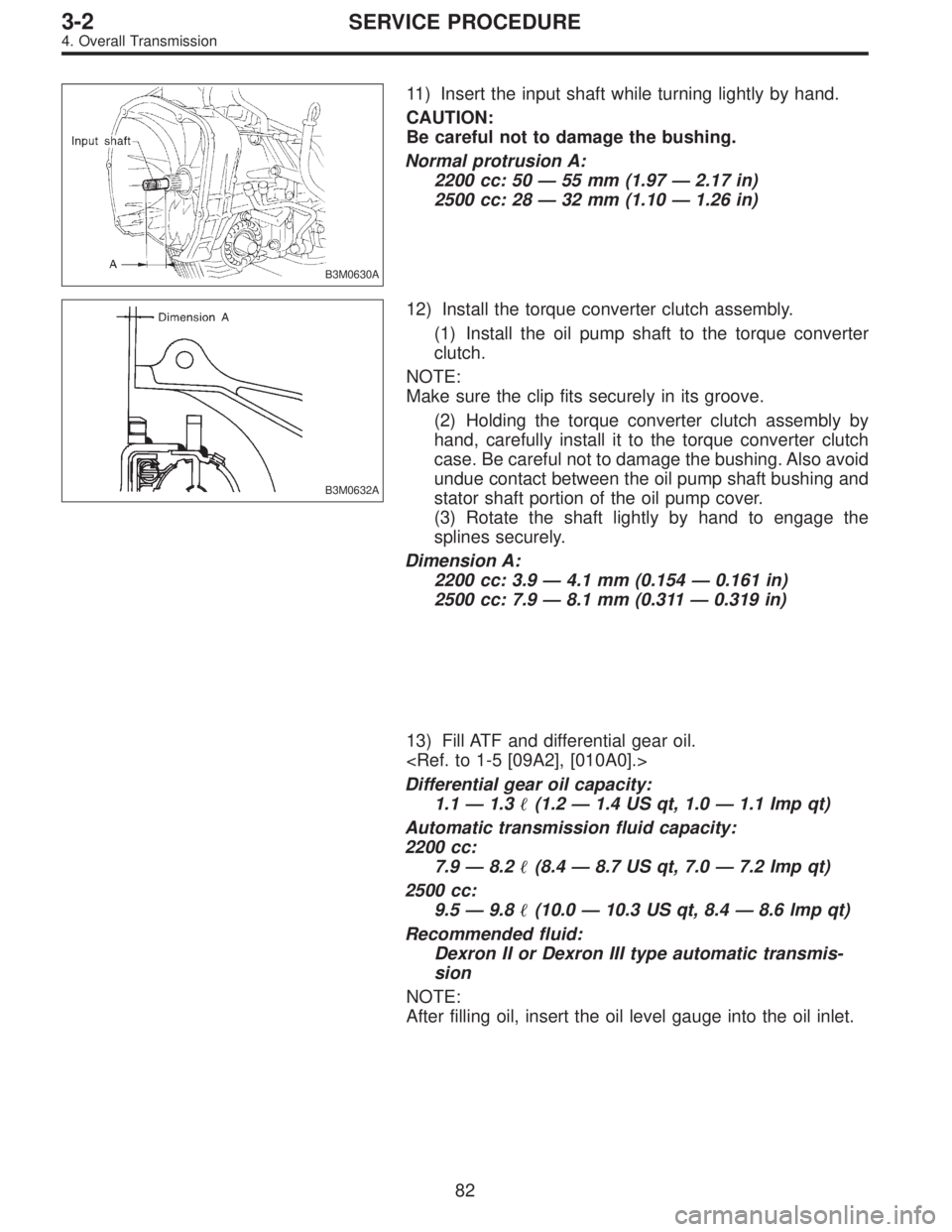
G4M0259
6) Invert both ST1 and housing.
7) Using ST2, press inner oil seal into housing until it
touches bottom.
ST1 927430000 HOUSING STAND
ST2 927460000 OIL SEAL INSTALLER
G4M0260
8) Using ST1 and ST2, press sub seal into place.
ST1 927430000 HOUSING STAND
ST2 927460000 OIL SEAL INSTALLER
9) Apply sufficient grease to oil seal lip.
Specified grease:
SHELL 6459N
CAUTION:
�If specified grease is not available, remove bearing
grease and apply Auto Rex A instead.
�Do not mix different types of grease.
G4M0261
10) Install back plate to rear housing.
Tightening torque:
52±6 N⋅m (5.3±0.6 kg-m, 38.3±4.3 ft-lb)
G4M0262
11) Using ST1 and ST2, press bearing into hub.
ST1 927080000 HUB STAND
ST2 927450000 HUB INSTALLER
21
4-2SERVICE PROCEDURE
2. Rear Axle (AWD Model)
Page 1180 of 3342
B4M0053A
10. Wheel Balancing
1) Proper wheel balance may be lost if the tire is repaired
or if it wears. Check the tire for dynamic balance, and repair
as necessary.
2) To check for dynamic balance, use a dynamic balancer.
Drive in the balance weight on both the top and rear sides
of the rim.
3) Some types of balancer can cause damage to the
wheel. Use an appropriate balancer when adjusting the
wheel balance.
4) Use genuine balance weights.
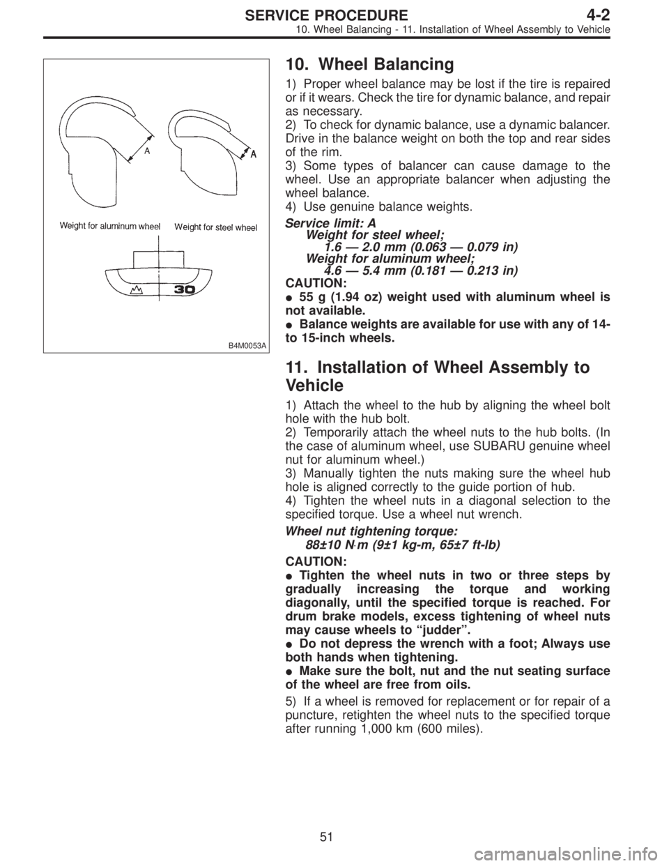
Service limit: A
Weight for steel wheel;
1.6—2.0 mm (0.063—0.079 in)
Weight for aluminum wheel;
4.6—5.4 mm (0.181—0.213 in)
CAUTION:
�55 g (1.94 oz) weight used with aluminum wheel is
not available.
�Balance weights are available for use with any of 14-
to 15-inch wheels.
11. Installation of Wheel Assembly to
Vehicle
1) Attach the wheel to the hub by aligning the wheel bolt
hole with the hub bolt.
2) Temporarily attach the wheel nuts to the hub bolts. (In
the case of aluminum wheel, use SUBARU genuine wheel
nut for aluminum wheel.)
3) Manually tighten the nuts making sure the wheel hub
hole is aligned correctly to the guide portion of hub.
4) Tighten the wheel nuts in a diagonal selection to the
specified torque. Use a wheel nut wrench.
Wheel nut tightening torque:
88±10 N⋅m (9±1 kg-m, 65±7 ft-lb)
CAUTION:
�Tighten the wheel nuts in two or three steps by
gradually increasing the torque and working
diagonally, until the specified torque is reached. For
drum brake models, excess tightening of wheel nuts
may cause wheels to “judder”.
�Do not depress the wrench with a foot; Always use
both hands when tightening.
�Make sure the bolt, nut and the nut seating surface
of the wheel are free from oils.
5) If a wheel is removed for replacement or for repair of a
puncture, retighten the wheel nuts to the specified torque
after running 1,000 km (600 miles).
51
4-2SERVICE PROCEDURE
10. Wheel Balancing - 11. Installation of Wheel Assembly to Vehicle
Page 1181 of 3342
B4M0053A
10. Wheel Balancing
1) Proper wheel balance may be lost if the tire is repaired
or if it wears. Check the tire for dynamic balance, and repair
as necessary.
2) To check for dynamic balance, use a dynamic balancer.
Drive in the balance weight on both the top and rear sides
of the rim.
3) Some types of balancer can cause damage to the
wheel. Use an appropriate balancer when adjusting the
wheel balance.
4) Use genuine balance weights.
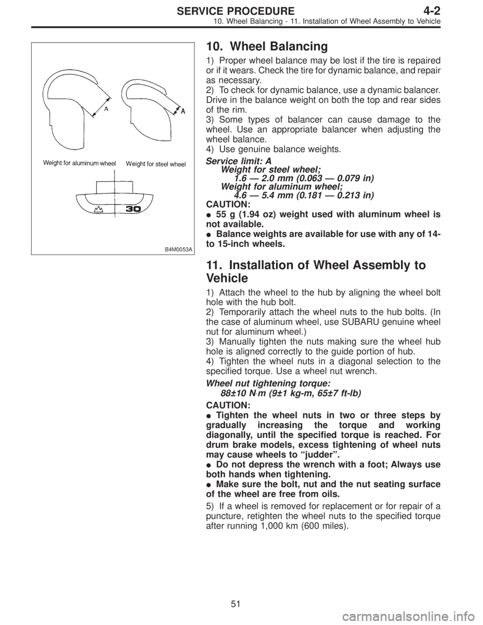
Service limit: A
Weight for steel wheel;
1.6—2.0 mm (0.063—0.079 in)
Weight for aluminum wheel;
4.6—5.4 mm (0.181—0.213 in)
CAUTION:
�55 g (1.94 oz) weight used with aluminum wheel is
not available.
�Balance weights are available for use with any of 14-
to 15-inch wheels.
11. Installation of Wheel Assembly to
Vehicle
1) Attach the wheel to the hub by aligning the wheel bolt
hole with the hub bolt.
2) Temporarily attach the wheel nuts to the hub bolts. (In
the case of aluminum wheel, use SUBARU genuine wheel
nut for aluminum wheel.)
3) Manually tighten the nuts making sure the wheel hub
hole is aligned correctly to the guide portion of hub.
4) Tighten the wheel nuts in a diagonal selection to the
specified torque. Use a wheel nut wrench.
Wheel nut tightening torque:
88±10 N⋅m (9±1 kg-m, 65±7 ft-lb)
CAUTION:
�Tighten the wheel nuts in two or three steps by
gradually increasing the torque and working
diagonally, until the specified torque is reached. For
drum brake models, excess tightening of wheel nuts
may cause wheels to “judder”.
�Do not depress the wrench with a foot; Always use
both hands when tightening.
�Make sure the bolt, nut and the nut seating surface
of the wheel are free from oils.
5) If a wheel is removed for replacement or for repair of a
puncture, retighten the wheel nuts to the specified torque
after running 1,000 km (600 miles).
51
4-2SERVICE PROCEDURE
10. Wheel Balancing - 11. Installation of Wheel Assembly to Vehicle
Page 1185 of 3342
1. Steering System
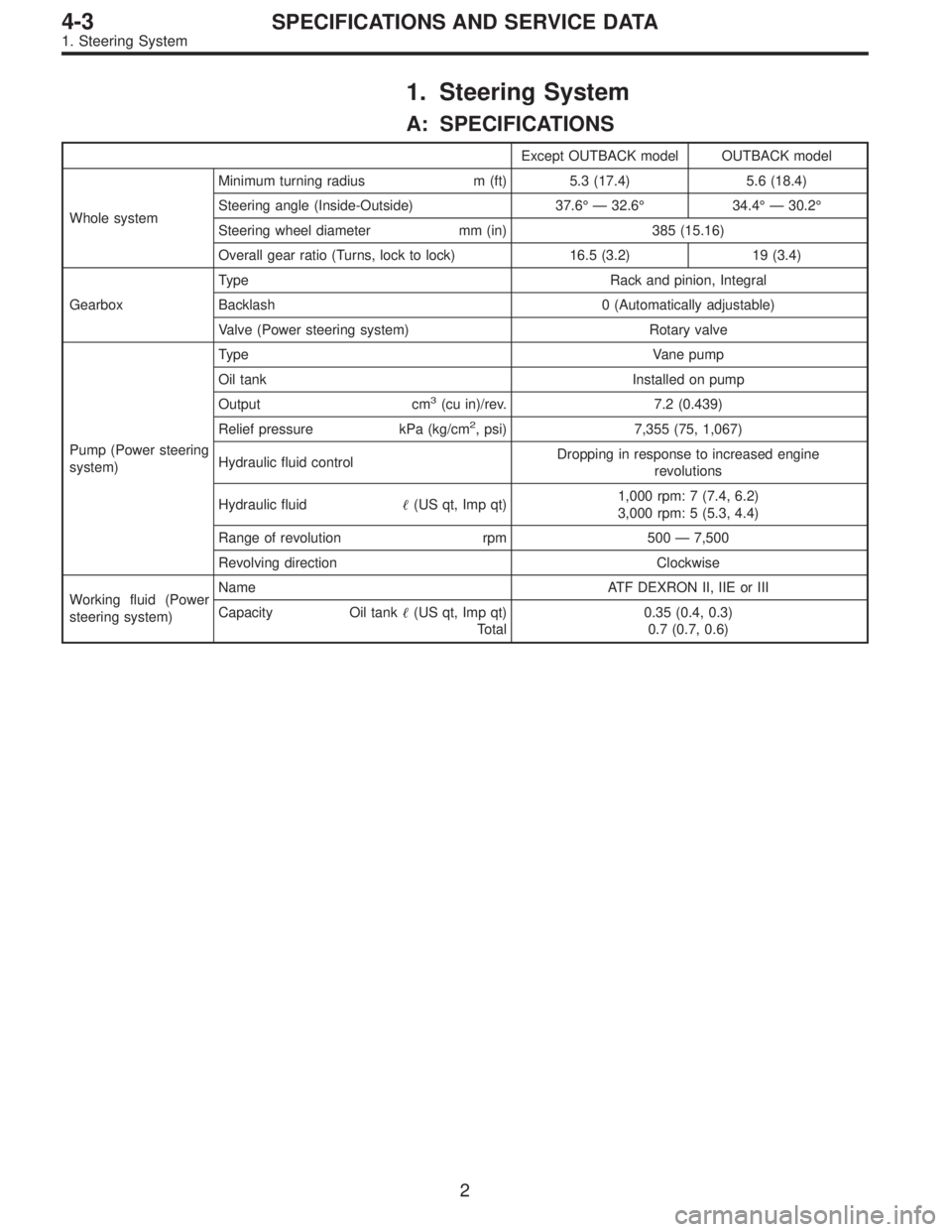
A: SPECIFICATIONS
Except OUTBACK model OUTBACK model
Whole systemMinimum turning radius m (ft) 5.3 (17.4) 5.6 (18.4)
Steering angle (Inside-Outside) 37.6°—32.6°34.4°—30.2°
Steering wheel diameter mm (in) 385 (15.16)
Overall gear ratio (Turns, lock to lock) 16.5 (3.2) 19 (3.4)
GearboxType Rack and pinion, Integral
Backlash 0 (Automatically adjustable)
Valve (Power steering system) Rotary valve
Pump (Power steering
system)Type Vane pump
Oil tank Installed on pump
Output cm
3(cu in)/rev. 7.2 (0.439)
Relief pressure kPa (kg/cm
2, psi) 7,355 (75, 1,067)
Hydraulic fluid controlDropping in response to increased engine
revolutions
Hydraulic fluid�(US qt, Imp qt)1,000 rpm: 7 (7.4, 6.2)
3,000 rpm: 5 (5.3, 4.4)
Range of revolution rpm 500—7,500
Revolving direction Clockwise
Working fluid (Power
steering system)Name ATF DEXRON II, IIE or III
Capacity Oil tank�(US qt, Imp qt)
Total0.35 (0.4, 0.3)
0.7 (0.7, 0.6)
2
4-3SPECIFICATIONS AND SERVICE DATA
1. Steering System
Page 1462 of 3342
1. Safety Precautions
1. HFC-134a AIR CONDITIONING SYSTEM
Component parts of the cooling system, refrigerant, com-
pressor oil, and other parts are not the same for the HFC-
134a system and the older CFC-12 system. Do not inter-
change parts or liquid.
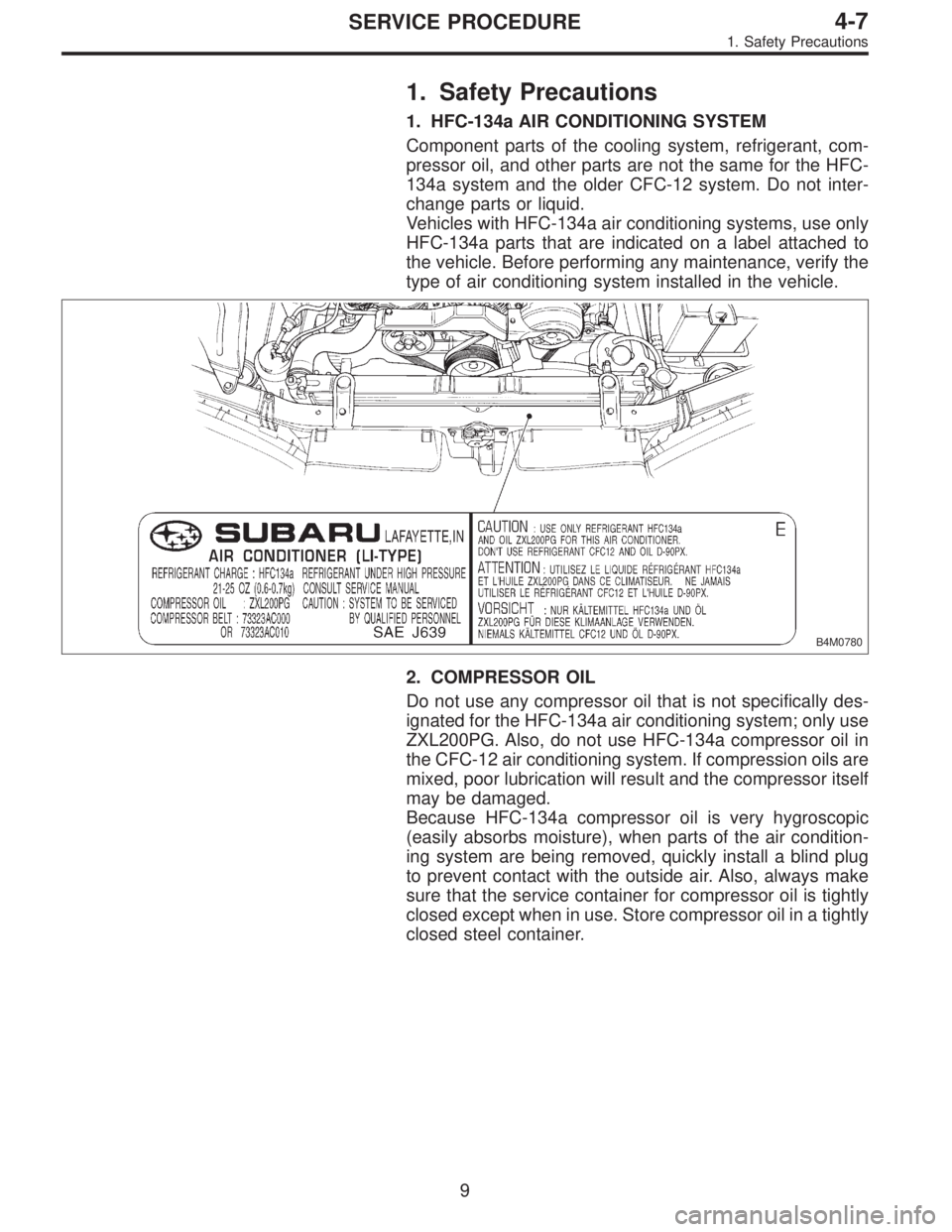
Vehicles with HFC-134a air conditioning systems, use only
HFC-134a parts that are indicated on a label attached to
the vehicle. Before performing any maintenance, verify the
type of air conditioning system installed in the vehicle.
B4M0780
2. COMPRESSOR OIL
Do not use any compressor oil that is not specifically des-
ignated for the HFC-134a air conditioning system; only use
ZXL200PG. Also, do not use HFC-134a compressor oil in
the CFC-12 air conditioning system. If compression oils are
mixed, poor lubrication will result and the compressor itself
may be damaged.
Because HFC-134a compressor oil is very hygroscopic
(easily absorbs moisture), when parts of the air condition-
ing system are being removed, quickly install a blind plug
to prevent contact with the outside air. Also, always make
sure that the service container for compressor oil is tightly
closed except when in use. Store compressor oil in a tightly
closed steel container.
9
4-7SERVICE PROCEDURE
1. Safety Precautions