Page 2249 of 3342
OBD0535
10CT6CHECK MAIN FAN RELAY 1, SUB FAN
RELAY 1 AND MAIN FAN RELAY.
1) Turn ignition switch to OFF.
2) Measure resistance between main fan relay 1 termi-
nals. (With A/C models only)
: Terminal
No. 1—No. 3:
Is the resistance between 87 and 107Ω?
: Go to next step 3).
: Replace main fan relay 1.
OBD0536
3) Remove sub fan relay 1. (With A/C models only)
Remove main fan relay. (Without A/C models only)
4) Measure resistance between sub fan relay 1 or main
fan relay terminals.
: Terminal
No. 1—No. 3:
Is the resistance between 83 and 117Ω?
: Go to step10CT7.
: Replace sub fan relay 1.
398
2-7ON-BOARD DIAGNOSTICS II SYSTEM
10. Diagnostic Chart with Trouble Code for LHD Vehicles
Page 2252 of 3342
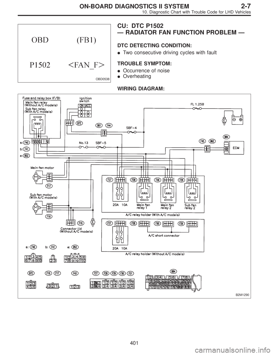
OBD0538
CU: DTC P1502
—RADIATOR FAN FUNCTION PROBLEM—
DTC DETECTING CONDITION:
�Two consecutive driving cycles with fault
TROUBLE SYMPTOM:
�Occurrence of noise
�Overheating
WIRING DIAGRAM:
B2M1290
401
2-7ON-BOARD DIAGNOSTICS II SYSTEM
10. Diagnostic Chart with Trouble Code for LHD Vehicles
Page 2253 of 3342
CAUTION:
After repair or replacement of faulty parts, conduct
CLEAR MEMORY and INSPECTION MODES.
NOTE:
If the vehicle, with the engine idling, is placed very close to
a wall or another vehicle, preventing normal cooling
function, the OBD system may detect malfunction.
10CU1CHECK ANY OTHER DTC (BESIDE DTC
P1502) ON DISPLAY.
: Is there any other DTC on display?
: Inspect the relevant DTC using“10. Diagnostics
Chart with Trouble Code”.
: Check engine cooling system.
[K100].>
402
2-7ON-BOARD DIAGNOSTICS II SYSTEM
10. Diagnostic Chart with Trouble Code for LHD Vehicles
Page 2255 of 3342
10CV1
CHECK DTC P0505 ON DISPLAY.
: Does the Subaru select monitor or OBD-II
general scan tool indicate DTC P0505?
: Inspect DTC P0505 using“10. Diagnostics Chart
with Trouble Code”.
NOTE:
In this case, it is not necessary to inspect DTC P1507.
: Go to step10CV2.
10CV2
CHECK AIR INTAKE SYSTEM.
1) Turn ignition switch to ON.
2) Start engine, and idle it.
: Is there a fault in air intake system?
NOTE:
Check the following items.
�Loose installation of intake manifold, idle air control sole-
noid valve and throttle body
�Cracks of intake manifold gasket, idle air control sole-
noid valve gasket and throttle body gasket
�Loose connections and cracks of idle air control solenoid
valve by-pass hoses
�Disconnections of vacuum hoses
: Repair air suction and leaks.
: Replace idle air control solenoid valve.
404
2-7ON-BOARD DIAGNOSTICS II SYSTEM
10. Diagnostic Chart with Trouble Code for LHD Vehicles
Page 2257 of 3342
 Turn ignition switch to OFF.
2) Connect test mode connector at the lower portion of
instrument panel (on the driver’s side), to the side of the
center")
OBD0736A
10CW1
CHECK OUTPUT SIGNAL FROM ECM.
1) Turn ignition switch to OFF.
2) Connect test mode connector at the lower portion of
instrument panel (on the driver’s side), to the side of the
center console box.
3) Turn ignition switch to ON.
B2M0608A
4) Measure voltage between ECM and chassis ground.
: Connector & terminal
(B84) No. 74 (+)—Chassis ground:
Does voltage change between 0 and 10
volts?
NOTE:
Radiator fan relay operation check can be executed using
Subaru Select Monitor (Function mode: FD03). For
procedure, refer to“COMPULSORY VALVE OPERATION
CHECK MODE”.
: Go to step10CW2.
: Even if MIL lights up, the circuit has returned to a
normal condition at this time. In this case, repair
poor contact in ECM connector.
B2M0611A
10CW2CHECK SHORT CIRCUIT IN RADIATOR
FAN RELAY 1 CONTROL CIRCUIT.
1) Turn ignition switch to OFF.
2) Remove main fan relay 1 and sub fan relay 1. (with A/C
models)
Remove main fan relay. (without A/C models)
3) Disconnect test mode connector.
4) Turn ignition switch to ON.
5) Measure voltage between ECM and chassis ground.
: Connector & terminal
(B84) No. 74 (+)—Chassis ground (�):
Is the voltage more than 10 V?
: Repair battery short circuit in radiator fan relay 1
control circuit. After repair, replace ECM.
: Go to next.
: Is there poor contact in ECM connector?
: Repair poor contact in ECM connector.
: Replace ECM.
406
2-7ON-BOARD DIAGNOSTICS II SYSTEM
10. Diagnostic Chart with Trouble Code for LHD Vehicles
Page 2260 of 3342
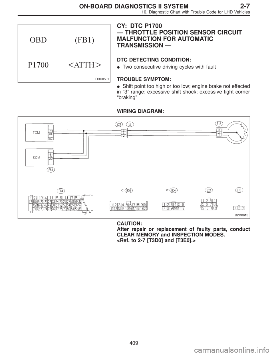
OBD0501
CY: DTC P1700
—THROTTLE POSITION SENSOR CIRCUIT
MALFUNCTION FOR AUTOMATIC
TRANSMISSION—
DTC DETECTING CONDITION:
�Two consecutive driving cycles with fault
TROUBLE SYMPTOM:
�Shift point too high or too low; engine brake not effected
in“3”range; excessive shift shock; excessive tight corner
“braking”
WIRING DIAGRAM:
B2M0613
CAUTION:
After repair or replacement of faulty parts, conduct
CLEAR MEMORY and INSPECTION MODES.
409
2-7ON-BOARD DIAGNOSTICS II SYSTEM
10. Diagnostic Chart with Trouble Code for LHD Vehicles
Page 2261 of 3342
10CY1
CHECK DTC P1700 ON DISPLAY.
: Does the Subaru select monitor or OBD-II
general scan tool indicate DTC P1700?
: Check throttle position sensor circuit.
[T7K0].>
: It is not necessary to inspect DTC P1700.
410
2-7ON-BOARD DIAGNOSTICS II SYSTEM
10. Diagnostic Chart with Trouble Code for LHD Vehicles
Page 2262 of 3342
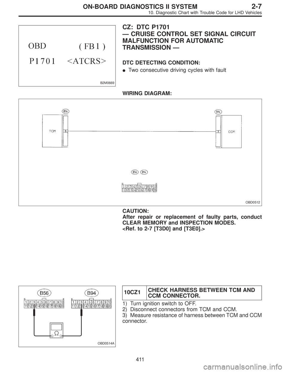
B2M0669
CZ: DTC P1701
—CRUISE CONTROL SET SIGNAL CIRCUIT
MALFUNCTION FOR AUTOMATIC
TRANSMISSION—
DTC DETECTING CONDITION:
�Two consecutive driving cycles with fault
WIRING DIAGRAM:
OBD0512
CAUTION:
After repair or replacement of faulty parts, conduct
CLEAR MEMORY and INSPECTION MODES.
OBD0514A
10CZ1CHECK HARNESS BETWEEN TCM AND
CCM CONNECTOR.
1) Turn ignition switch to OFF.
2) Disconnect connectors from TCM and CCM.
3) Measure resistance of harness between TCM and CCM
connector.
411
2-7ON-BOARD DIAGNOSTICS II SYSTEM
10. Diagnostic Chart with Trouble Code for LHD Vehicles
 Turn ignition switch to OFF.
2) Measure resistance between main fan relay 1 termi-
nals. (With A/C models only)
: Terminal
N")
![SUBARU LEGACY 1997 Service Repair Manual CAUTION:
After repair or replacement of faulty parts, conduct
CLEAR MEMORY and INSPECTION MODES.
<Ref. to 2-7 [T3D0] and [T3E0].>
NOTE:
If the vehicle, with the engine idling, is placed very close to](/manual-img/17/57434/w960_57434-2252.png "SUBARU LEGACY 1997 Service Repair Manual CAUTION:
After repair or replacement of faulty parts, conduct
CLEAR MEMORY and INSPECTION MODES.
<Ref. to 2-7 [T3D0] and [T3E0].>
NOTE:
If the vehicle, with the engine idling, is placed very close to")

![SUBARU LEGACY 1997 Service Repair Manual 10CY1
CHECK DTC P1700 ON DISPLAY.
: Does the Subaru select monitor or OBD-II
general scan tool indicate DTC P1700?
: Check throttle position sensor circuit. <Ref. to 3-2
[T7K0].>
: It is not necessary](/manual-img/17/57434/w960_57434-2260.png "SUBARU LEGACY 1997 Service Repair Manual 10CY1
CHECK DTC P1700 ON DISPLAY.
: Does the Subaru select monitor or OBD-II
general scan tool indicate DTC P1700?
: Check throttle position sensor circuit. <Ref. to 3-2
[T7K0].>
: It is not necessary")