Page 2177 of 3342
![SUBARU LEGACY 1997 Service Repair Manual 10BV2
CHECK INHIBITOR SWITCH CIRCUIT.
Check inhibitor switch circuit. <Ref. to 2-7 [T10BI0].>
: Is there any trouble in inhibitor switch cir-
cuit?
: Repair or replace inhibitor switch circuit.
: Go t SUBARU LEGACY 1997 Service Repair Manual 10BV2
CHECK INHIBITOR SWITCH CIRCUIT.
Check inhibitor switch circuit. <Ref. to 2-7 [T10BI0].>
: Is there any trouble in inhibitor switch cir-
cuit?
: Repair or replace inhibitor switch circuit.
: Go t](/manual-img/17/57434/w960_57434-2176.png)
10BV2
CHECK INHIBITOR SWITCH CIRCUIT.
Check inhibitor switch circuit.
: Is there any trouble in inhibitor switch cir-
cuit?
: Repair or replace inhibitor switch circuit.
: Go to step10BV3.
OBD0145A
10BV3
CHECK GEAR POSITION.
1) Turn ignition switch to OFF.
2) Connect the Subaru select monitor to data link connec-
tor.
3) Lift-up or raise the vehicle and support with safety
stands.
CAUTION:
On AWD models, raise all wheels off ground.
4) Start and warm-up the engine and transmission.
H2M1150
5) Subaru select monitor switch to ON.
6) Select AT mode using function key.
Press the function key [/], and change to AT mode.
7) Press the function key [0].
G3M0152
8) Designate mode using function key.
Function mode for AT: F10
OBD0615
9) Move selector lever to“D”and drive the vehicle.
10) Read data on Subaru select monitor.
: Does gear position change according to
throttle position and vehicle speed?
: Go to next.
: Go to step10BV4.
: Is there poor contact in TCM connector?
: Repair poor contact in TCM connector.
: Go to next.
326
2-7ON-BOARD DIAGNOSTICS II SYSTEM
10. Diagnostic Chart with Trouble Code for LHD Vehicles
Page 2179 of 3342
B2M0667
BW: DTC P0763
—SHIFT SOLENOID C (SHIFT SOLENOID 3)
ELECTRICAL—
DTC DETECTING CONDITION:
�Two consecutive driving cycles with fault
TROUBLE SYMPTOM:
�Ineffective engine brake with selector lever in“3”
WIRING DIAGRAM:
OBD0452
CAUTION:
After repair or replacement of faulty parts, conduct
CLEAR MEMORY and INSPECTION MODES.
10BW1
CHECK DTC P0763 ON DISPLAY.
: Does the Subaru select monitor or OBD-II
general scan tool indicate DTC P0763?
: Check shift solenoid 3 circuit.
: It is not necessary to inspect DTC P0763.
328
2-7ON-BOARD DIAGNOSTICS II SYSTEM
10. Diagnostic Chart with Trouble Code for LHD Vehicles
Page 2184 of 3342

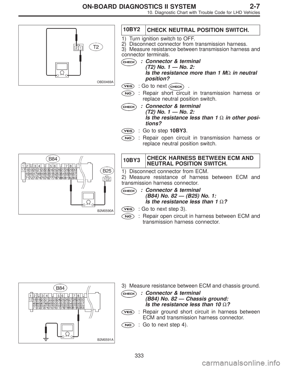
OBD0469A
10BY2
CHECK NEUTRAL POSITION SWITCH.
1) Turn ignition switch to OFF.
2) Disconnect connector from transmission harness.
3) Measure resistance between transmission harness and
connector terminals.
: Connector & terminal
(T2) No. 1—No. 2:
Is the resistance more than 1 MΩin neutral
position?
: Go to next.
: Repair short circuit in transmission harness or
replace neutral position switch.
: Connector & terminal
(T2) No. 1—No. 2:
Is the resistance less than 1Ωin other posi-
tions?
: Go to step10BY3.
: Repair open circuit in transmission harness or
replace neutral position switch.
B2M0590A
10BY3CHECK HARNESS BETWEEN ECM AND
NEUTRAL POSITION SWITCH.
1) Disconnect connector from ECM.
2) Measure resistance of harness between ECM and
transmission harness connector.
: Connector & terminal
(B84) No. 82—(B25) No. 1:
Is the resistance less than 1Ω?
: Go to next step 3).
: Repair open circuit in harness between ECM and
transmission harness connector.
B2M0591A
3) Measure resistance between ECM and chassis ground.
: Connector & terminal
(B84) No. 82—Chassis ground:
Is the resistance less than 10Ω?
: Repair ground short circuit in harness between
ECM and transmission harness connector.
: Go to next step 4).
333
2-7ON-BOARD DIAGNOSTICS II SYSTEM
10. Diagnostic Chart with Trouble Code for LHD Vehicles
Page 2185 of 3342
OBD0472A
4) Measure resistance of harness between transmission
harness connector and engine ground.
: Connector & terminal
(B25) No. 2—Engine ground:
Is the resistance less than 5Ω?
: Go to next.
: Repair harness and connector.
NOTE:
In this case, repair the following:
�Open circuit in harness between transmission harness
connector and engine grounding terminal
�Poor contact in coupling connector (B22)
: Is there poor contact in transmission har-
ness connector?
: Repair poor contact in transmission harness con-
nector.
: Replace ECM.
334
2-7ON-BOARD DIAGNOSTICS II SYSTEM
10. Diagnostic Chart with Trouble Code for LHD Vehicles
Page 2187 of 3342

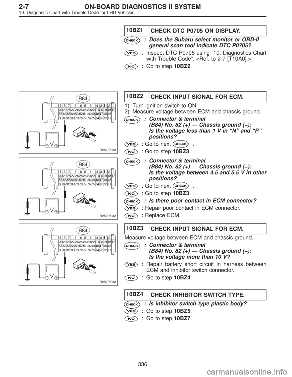
10BZ1
CHECK DTC P0705 ON DISPLAY.
: Does the Subaru select monitor or OBD-II
general scan tool indicate DTC P0705?
: Inspect DTC P0705 using“10. Diagnostics Chart
with Trouble Code”.
: Go to step10BZ2.
B2M0593A
10BZ2
CHECK INPUT SIGNAL FOR ECM.
1) Turn ignition switch to ON.
2) Measure voltage between ECM and chassis ground.
: Connector & terminal
(B84) No. 82 (+)—Chassis ground (�):
Is the voltage less than1Vin“N”and“P”
positions?
: Go to next.
: Go to step10BZ3.
B2M0593A
: Connector & terminal
(B84) No. 82 (+)—Chassis ground (�):
Is the voltage between 4.5 and 5.5 V in other
positions?
: Go to next.
: Go to step10BZ3.
: Is there poor contact in ECM connector?
: Repair poor contact in ECM connector.
: Replace ECM.
B2M0593A
10BZ3
CHECK INPUT SIGNAL FOR ECM.
Measure voltage between ECM and chassis ground.
: Connector & terminal
(B84) No. 82 (+)—Chassis ground (�):
Is the voltage more than 10 V?
: Repair battery short circuit in harness between
ECM and inhibitor switch connector.
: Go to step10BZ4.
10BZ4
CHECK INHIBITOR SWITCH TYPE.
: Is inhibitor switch type plastic body?
: Go to step10BZ5.
: Go to step10BZ7.
336
2-7ON-BOARD DIAGNOSTICS II SYSTEM
10. Diagnostic Chart with Trouble Code for LHD Vehicles
Page 2189 of 3342

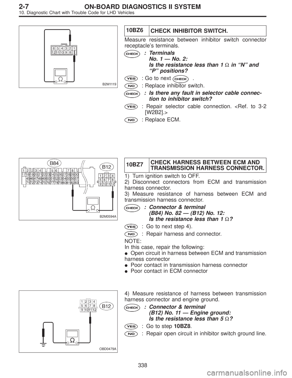
B2M1119
10BZ6
CHECK INHIBITOR SWITCH.
Measure resistance between inhibitor switch connector
receptacle’s terminals.
: Terminals
No. 1—No. 2:
Is the resistance less than 1Ωin“N”and
“P”positions?
: Go to next.
: Replace inhibitor switch.
: Is there any fault in selector cable connec-
tion to inhibitor switch?
: Repair selector cable connection.
[W2B2].>
: Replace ECM.
B2M0594A
10BZ7CHECK HARNESS BETWEEN ECM AND
TRANSMISSION HARNESS CONNECTOR.
1) Turn ignition switch to OFF.
2) Disconnect connectors from ECM and transmission
harness connector.
3) Measure resistance of harness between ECM and
transmission harness connector.
: Connector & terminal
(B84) No. 82—(B12) No. 12:
Is the resistance less than 1Ω?
: Go to next step 4).
: Repair harness and connector.
NOTE:
In this case, repair the following:
�Open circuit in harness between ECM and transmission
harness connector
�Poor contact in transmission harness connector
�Poor contact in ECM connector
OBD0479A
4) Measure resistance of harness between transmission
harness connector and engine ground.
: Connector & terminal
(B12) No. 11—Engine ground:
Is the resistance less than 5Ω?
: Go to step10BZ8.
: Repair open circuit in inhibitor switch ground line.
338
2-7ON-BOARD DIAGNOSTICS II SYSTEM
10. Diagnostic Chart with Trouble Code for LHD Vehicles
Page 2191 of 3342
OBD0481
CA: DTC P1102
—PRESSURE SOURCES SWITCHING
SOLENOID VALVE CIRCUIT LOW INPUT—
DTC DETECTING CONDITION:
�Two consecutive driving cycles with fault
TROUBLE SYMPTOM:
�Erroneous idling
�Failure of engine to start
WIRING DIAGRAM:
B2M1308
CAUTION:
After repair or replacement of faulty parts, conduct
CLEAR MEMORY and INSPECTION MODE.
B2M0596A
10CA1
CHECK OUTPUT SIGNAL FROM ECM.
1) Turn ignition switch to ON.
2) Measure voltage between ECM and chassis ground.
: Connector & terminal
(B84) No. 15 (+)—Chassis ground (�):
Is the voltage more than 10 V?
: Go to next.
: Go to step10CA2.
: Is there poor contact in ECM connector?
340
2-7ON-BOARD DIAGNOSTICS II SYSTEM
10. Diagnostic Chart with Trouble Code for LHD Vehicles
Page 2192 of 3342

: Repair poor contact in ECM connector.
: Contact with SOA service.
NOTE:
Inspection by DTM is required, because probable cause is
deterioration of multiple parts.
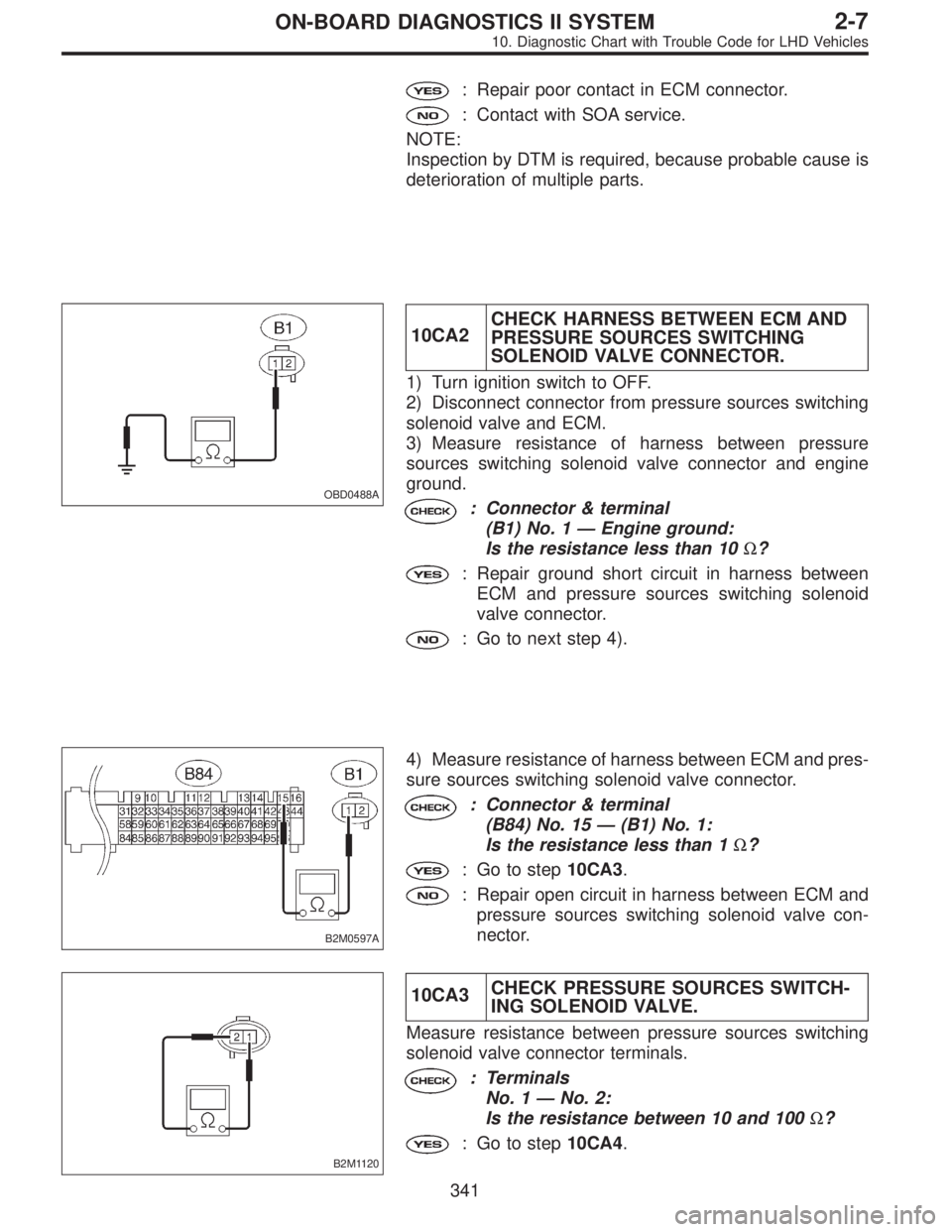
OBD0488A
10CA2CHECK HARNESS BETWEEN ECM AND
PRESSURE SOURCES SWITCHING
SOLENOID VALVE CONNECTOR.
1) Turn ignition switch to OFF.
2) Disconnect connector from pressure sources switching
solenoid valve and ECM.
3) Measure resistance of harness between pressure
sources switching solenoid valve connector and engine
ground.
: Connector & terminal
(B1) No. 1—Engine ground:
Is the resistance less than 10Ω?
: Repair ground short circuit in harness between
ECM and pressure sources switching solenoid
valve connector.
: Go to next step 4).
B2M0597A
4) Measure resistance of harness between ECM and pres-
sure sources switching solenoid valve connector.
: Connector & terminal
(B84) No. 15—(B1) No. 1:
Is the resistance less than 1Ω?
: Go to step10CA3.
: Repair open circuit in harness between ECM and
pressure sources switching solenoid valve con-
nector.
B2M1120
10CA3CHECK PRESSURE SOURCES SWITCH-
ING SOLENOID VALVE.
Measure resistance between pressure sources switching
solenoid valve connector terminals.
: Terminals
No. 1—No. 2:
Is the resistance between 10 and 100Ω?
: Go to step10CA4.
341
2-7ON-BOARD DIAGNOSTICS II SYSTEM
10. Diagnostic Chart with Trouble Code for LHD Vehicles