Page 481 of 3342
B2M0340
(3) Remove bolts which secure power steering pipe
brackets to intake manifold.
NOTE:
Do not disconnect power steering hose.
B2M0334
(4) Remove bolts which install power steering pump to
bracket.
B2M0029
(5) Place power steering pump on the right side wheel
apron.
B6M0772
14) Disconnect spark plug cords from ignition coil.
B2M1239
15) Disconnect PCV hose from intake manifold.
12
2-7SERVICE PROCEDURE
4. Intake Manifold
Page 489 of 3342
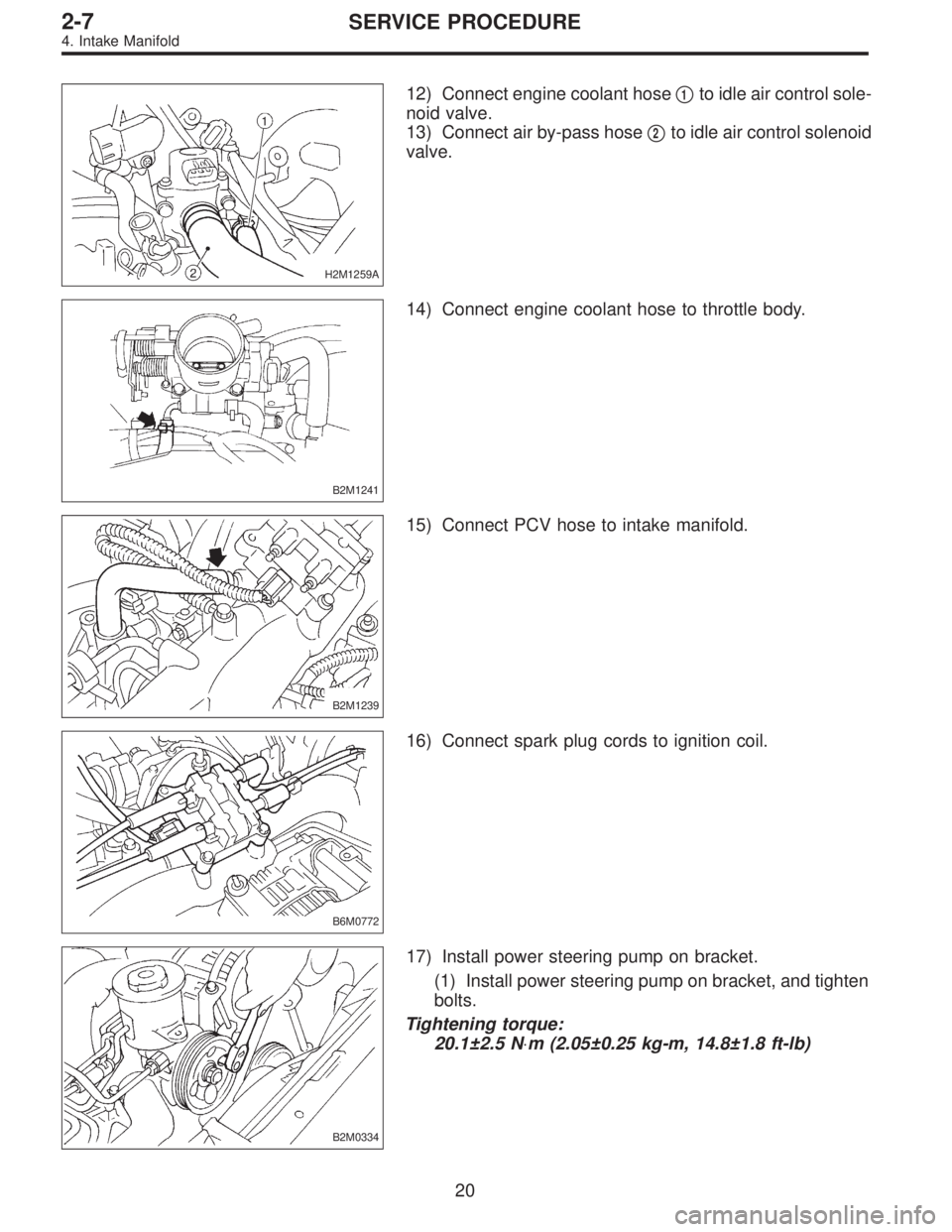
H2M1259A
12) Connect engine coolant hose�1to idle air control sole-
noid valve.
13) Connect air by-pass hose�
2to idle air control solenoid
valve.
B2M1241
14) Connect engine coolant hose to throttle body.
B2M1239
15) Connect PCV hose to intake manifold.
B6M0772
16) Connect spark plug cords to ignition coil.
B2M0334
17) Install power steering pump on bracket.
(1) Install power steering pump on bracket, and tighten
bolts.
Tightening torque:
20.1±2.5 N⋅m (2.05±0.25 kg-m, 14.8±1.8 ft-lb)
20
2-7SERVICE PROCEDURE
4. Intake Manifold
Page 490 of 3342
B2M0340
(2) Install power steering pipe brackets on right side
intake manifold.
G2M0286
(3) Install power steering pump drive V-belt.
(4) Adjust V-belt.
B2M0017
(5) Install V-belt cover.
B2M1231A
18) Connect vacuum hoses to pressure sources switching
solenoid valve.
G2M0280
19) Connect accelerator cable�1.
20) Connect cruise control cable�
2. (With cruise control
model)
21
2-7SERVICE PROCEDURE
4. Intake Manifold
Page 596 of 3342

2. Engine
A: REMOVAL
1. Set the vehicle on lift arms.
2. Open front hood and support with a stay.
3. Release fuel pressure.
4. Disconnect battery cable and remove battery from vehicle.
5. Drain coolant.
6. Remove cooling system.
With A/C
7. Collect refrigerant, and remove pressure hoses.
8. Remove air intake system.
9. Remove canister and bracket.
10. Disconnect connectors, cables and hoses.
11. Remove power steering pump from bracket.
12. Remove front exhaust pipe and center exhaust pipe.
13. Remove nuts which hold lower side of transmission to
engine.
14. Remove nuts which install front cushion rubber onto front
crossmember.
AT model
15. Separate torque converter from drive plate.
16. Remove pitching stopper.
17. Disconnect fuel delivery hose, return hose and evaporation
hoses.
18. Support engine with a lifting device and wire ropes.
19. Support transmission with a garage jack.
20. Remove bolts which hold upper side of transmission to
engine.
21. Remove engine from vehicle.
�
�
�
�
�
�
�
�
�
�
�
�
�
�
�
8
2-11SERVICE PROCEDURE
2. Engine
Page 604 of 3342
G2M0286
11) Remove power steering pump from bracket.
(1) Loosen lock bolt and slider bolt, and remove front
side V-belt.
B2M0340
(2) Remove pipe with bracket from intake manifold.
B2M0334
(3) Remove bolts which install power steering pump
from bracket.
B2M0029
(4) Place power steering pump on the right side wheel
apron.
G2M0290
12) Remove front exhaust pipe and center exhaust pipe.
(1) Lift-up the vehicle.
(2) Remove nuts which install front exhaust pipe onto
engine.
16
2-11SERVICE PROCEDURE
2. Engine
Page 608 of 3342

B: INSTALLATION
1. Install engine to transmission.
2. Tighten bolts which hold upper side of transmission to engine.
3. Remove lifting device and wire rope.
4. Remove garage jack.
5. Install pitching stopper.
AT model
6. Install torque converter onto drive plate.
7. Install canister and bracket.
8. Install power steering pump on bracket.
9. Tighten nuts which hold lower side of transmission to engine.
10. Tighten nuts which install front cushion rubber onto cross-
member.
11. Install front exhaust pipe and center exhaust pipe.
12. Connect hoses, connectors and cables.
13. Install air intake system.
�Air intake duct
�Air cleaner element and upper cover.
With A/C
14. Install A/C pressure hoses.
15. Install cooling system.
16. Install battery onto the vehicle, and connect cables.
17. Fill coolant.
18. Check ATF level, and connect if necessary. [AT]
19. Correct power steering oil, and bleed air.
20. Remove front hood stay, and close front hood.
21. Take off the vehicle from lift arms.
�
�
�
�
�
�
�
�
�
�
�
�
20
2-11SERVICE PROCEDURE
2. Engine
Page 610 of 3342
G2M0302
5) Install pitching stopper.
Tightening torque:
T1: 49±5 N⋅m (5.0±0.5 kg-m, 36.2±3.6 ft-lb)
T2: 57±10 N⋅m (5.8±1.0 kg-m, 42±7 ft-lb)
G2M0294
6) Install torque converter onto drive plate. (AT model)
(1) Tighten bolts which hold torque converter to drive
plate.
(2) Tighten other bolts while rotating the engine by
using ST.
ST 499977000 CRANK PULLEY WRENCH
CAUTION:
Be careful not to drop bolts into torque converter
housing.
Tightening torque:
25±2 N⋅m (2.5±0.2 kg-m, 18.1±1.4 ft-lb)
(3) Clog plug onto service hole.
G2M0272
7) Install canister and bracket. (2500 cc, 2200 cc FWD and
Taiwan spec. vehicles)
B2M0334
8) Install power steering pump on bracket.
(1) Install power steering pump on bracket, and tighten
bolts.
Tightening torque:
39±10 N⋅m (4.0±1.0 kg-m, 29±7 ft-lb)
22
2-11SERVICE PROCEDURE
2. Engine
Page 611 of 3342
B2M0340
(2) Install power steering pipe bracket on right side
intake manifold, and install spark plug codes.
G2M0286
(3) Install front side V-belt, and adjust it.
G2M0292
9) Tighten nuts which hold lower side of transmission to
engine.
Tightening torque:
50±4 N⋅m (5.1±0.4 kg-m, 36.9±2.9 ft-lb)
G2M0303
10) Tighten nuts which install front cushion rubber onto
crossmember.
Tightening torque:
69±15 N⋅m (7.0±1.5 kg-m, 51±11 ft-lb)
CAUTION:
Be sure to tighten front cushion rubber mounting bolts
in the innermost elliptical hole in the front crossmem-
ber.
23
2-11SERVICE PROCEDURE
2. Engine
 Remove bolts which secure power steering pipe
brackets to intake manifold.
NOTE:
Do not disconnect power steering hose.
B2M0334
(4) Remove bolts which install power steering pump to
bracke")
![SUBARU LEGACY 1997 Service Repair Manual B2M0340
(2) Install power steering pipe brackets on right side
intake manifold.
G2M0286
(3) Install power steering pump drive V-belt.
(4) Adjust V-belt. <Ref. to 1-5 [01A0].>
B2M0017
(5) Install V-bel](/manual-img/17/57434/w960_57434-489.png "SUBARU LEGACY 1997 Service Repair Manual B2M0340
(2) Install power steering pipe brackets on right side
intake manifold.
G2M0286
(3) Install power steering pump drive V-belt.
(4) Adjust V-belt. <Ref. to 1-5 [01A0].>
B2M0017
(5) Install V-bel")
 Remove power steering pump from bracket.
(1) Loosen lock bolt and slider bolt, and remove front
side V-belt.
B2M0340
(2) Remove pipe with bracket from intake manifold.
B2M0334
(3) Remove b")
 Install pitching stopper.
Tightening torque:
T1: 49±5 N⋅m (5.0±0.5 kg-m, 36.2±3.6 ft-lb)
T2: 57±10 N⋅m (5.8±1.0 kg-m, 42±7 ft-lb)
G2M0294
6) Install torque converter onto drive pl")
![SUBARU LEGACY 1997 Service Repair Manual B2M0340
(2) Install power steering pipe bracket on right side
intake manifold, and install spark plug codes.
G2M0286
(3) Install front side V-belt, and adjust it.
<Ref. to 1-5 [01A0].>
G2M0292
9) Tigh](/manual-img/17/57434/w960_57434-610.png "SUBARU LEGACY 1997 Service Repair Manual B2M0340
(2) Install power steering pipe bracket on right side
intake manifold, and install spark plug codes.
G2M0286
(3) Install front side V-belt, and adjust it.
<Ref. to 1-5 [01A0].>
G2M0292
9) Tigh")